EP2975731A2 - Rotor a disque pour une machine electrique - Google Patents
Rotor a disque pour une machine electrique Download PDFInfo
- Publication number
- EP2975731A2 EP2975731A2 EP15167077.5A EP15167077A EP2975731A2 EP 2975731 A2 EP2975731 A2 EP 2975731A2 EP 15167077 A EP15167077 A EP 15167077A EP 2975731 A2 EP2975731 A2 EP 2975731A2
- Authority
- EP
- European Patent Office
- Prior art keywords
- permanent magnets
- support member
- pancake
- rotor
- recesses
- Prior art date
- Legal status (The legal status is an assumption and is not a legal conclusion. Google has not performed a legal analysis and makes no representation as to the accuracy of the status listed.)
- Granted
Links
Images


Classifications
-
- H—ELECTRICITY
- H02—GENERATION; CONVERSION OR DISTRIBUTION OF ELECTRIC POWER
- H02K—DYNAMO-ELECTRIC MACHINES
- H02K1/00—Details of the magnetic circuit
- H02K1/06—Details of the magnetic circuit characterised by the shape, form or construction
- H02K1/22—Rotating parts of the magnetic circuit
- H02K1/27—Rotor cores with permanent magnets
- H02K1/2793—Rotors axially facing stators
- H02K1/2795—Rotors axially facing stators the rotor consisting of two or more circumferentially positioned magnets
- H02K1/2796—Rotors axially facing stators the rotor consisting of two or more circumferentially positioned magnets where both axial sides of the rotor face a stator
-
- H—ELECTRICITY
- H02—GENERATION; CONVERSION OR DISTRIBUTION OF ELECTRIC POWER
- H02K—DYNAMO-ELECTRIC MACHINES
- H02K9/00—Arrangements for cooling or ventilating
- H02K9/22—Arrangements for cooling or ventilating by solid heat conducting material embedded in, or arranged in contact with, the stator or rotor, e.g. heat bridges
- H02K9/223—Heat bridges
-
- H—ELECTRICITY
- H02—GENERATION; CONVERSION OR DISTRIBUTION OF ELECTRIC POWER
- H02K—DYNAMO-ELECTRIC MACHINES
- H02K21/00—Synchronous motors having permanent magnets; Synchronous generators having permanent magnets
- H02K21/12—Synchronous motors having permanent magnets; Synchronous generators having permanent magnets with stationary armatures and rotating magnets
- H02K21/24—Synchronous motors having permanent magnets; Synchronous generators having permanent magnets with stationary armatures and rotating magnets with magnets axially facing the armatures, e.g. hub-type cycle dynamos
Definitions
- the invention relates to electrical machines with disc rotors, in particular axial flow or transverse flux machines. Furthermore, the present invention relates to the construction of disc rotors for the reduction of heat generation and to improve the heat dissipation.
- Electric machines in particular permanent magnet-excited electric machines with disc rotors, are known from the prior art.
- the document shows WO 2009/115247 an axial flow machine with a disc rotor, which is constructed essentially of a non-magnetic material, in particular a plastic, are embedded in the permanent magnets.
- permanent magnets may have a proportion of rare earths, such as NdFeB magnets.
- the remanence of such permanent magnets is strongly temperature-dependent and increases with increasing temperature from.
- Such permanent magnets also have a temperature-dependent coercive force, which also decreases with an increase in temperature. If the decreasing coercive field strength during operation leads to a reversal of the magnetic field direction by the permanent magnet, this can lead to demagnetization and thus damage or destruction of the electrical machines.
- One idea of the above disc rotor is to construct the pancake other than the permanent magnets using multiple materials.
- an electrically nonconductive second material is used in the region of the permanent magnets and a thermally conductive first material is arranged between the permanent magnet and the rotor shaft.
- this ensures a good and uniform heat dissipation from the permanent magnets to the rotor shaft, and, on the other hand, the generation of heat due to induced eddy currents in the region of the permanent magnets is prevented or reduced, without adversely affecting the mechanical stability of the disc rotor.
- the first material may have a higher thermal conductivity than the second material and / or the first material may have a higher electrical conductivity than the second material.
- the rotor body has a radially inner support element with the first material and a support cage surrounding the support member with the second material, wherein the holding cage defines recesses to receive the permanent magnets.
- the permanent magnets may abut an outer circumference of the support member so that heat in the permanent magnets may be dissipated radially inwardly over the support member, and wherein the permanent magnets are connected to the support member via a thermal coupling means, such as e.g. a thermal compound, are coupled.
- a thermal coupling means such as e.g. a thermal compound
- the holding cage can be positively connected to the carrier element.
- the rotor body may include a support member having the first material having on one or both sides magnet receiving portions as axially directed recesses for receiving permanent magnets, wherein a sheathing with the second material is provided to at least partially surround or cover the permanent magnets ,
- the support member may have a circumferential in the axial direction of one or both sides projecting edge to hold the permanent magnets in the magnetic receiving areas.
- the rotor body comprises a carrier element with the first material, which is provided with continuous recesses for receiving circumferentially adjacent permanent magnets, wherein a sheath with the second material is provided to at least partially surround the permanent magnets or to cover.
- the support element may have, in a region which is radially outer with respect to the recesses, segments which extend alternately in the axial direction, in particular with respect to the circumferential direction
- the carrier element can be designed in multiple layers.
- the support member may be provided at a radially outer edge of the recesses with an axially extending portion.
- the carrier element may be provided on at least one side with structuring.
- an electric machine having the above pancake and a stator assembly having at least one stator unit, the pancake being axially offset from the stator unit.
- FIG. 1 shows a cross-sectional view through an electric machine 1 with a pancake 2 and a stator 3 arranged.
- the pancake 2 has an annular rotor body 21 and is rotatably supported on a rotor shaft 4.
- the rotor body 21 may be coupled directly to the rotor shaft 4 or via a e.g. cup-shaped support member 22 may be coupled to the rotor shaft 4 at an axially offset position.
- the rotor body 21 of the disc rotor 2 may be arranged between two stator units 31 of the stator assembly 3.
- Each of the stator units 31 may each have stator teeth 32 projecting in the axial direction A.
- the stator teeth 31 can furthermore be arranged concentrically around the axis of rotation of the rotor shaft 4 in the circumferential direction at a distance from one another.
- the stator units 31 may each comprise circumferential stator windings (not shown) which may be energized to alternately magnetize the stator teeth 32.
- the pancake 2 may be provided in a magnetically active region with permanent magnets 23 which are arranged side by side in the circumferential direction and which may have a Polraum in the circumferential direction. Rotor poles are thereby formed between the permanent magnets 23 of the disc rotor 2. Alternatively, the poling direction of the permanent magnets 23 may also be in the axial direction.
- FIGS. 2a and 2b show a plan view of a pancake 2 and a cross-sectional view transverse to the circumferential direction through a pancake 2, which is designed to reduce heat generation and to improve heat dissipation.
- the rotor body 21 of the disc rotor 2 has a carrier element 24 which is arranged between the permanent magnet 23 and the rotor shaft 4.
- the carrier element 24 has a substantially circular or polygonal outer contour on, to which the corresponding facing surfaces of the permanent magnets 4 connect so that they are thermally coupled to the support member 24, that is, between the permanent magnet 4 and the support member 24 is a high thermal conductivity.
- the outer contour of the carrier element 24 is formed so that the facing side of the permanent magnet 23 abuts flat against it.
- the permanent magnets 4 are held by a holding cage 25 of the rotor body 21, the recesses 26 for receiving the permanent magnets 4 has.
- the holding cage 25 has radially outside the recesses 26 bridge elements 27 which extend over the permanent magnets 23 and hold them in the recesses 26.
- Legs 28 extend between the permanent magnets 23 of the disc rotor 2.
- the holding cage 25 is connected to the carrier element 24 by protruding ends of the legs 28.
- the carrier element 24 is formed from a thermally highly conductive material, in particular from a metal.
- the carrier element 24 may be formed, for example, from laminations.
- the holding cage 25, which is arranged with the bridge elements 27 radially outside and with its legs 28 between the permanent magnets 23, is preferably made of an electrically non-conductive material, such as a plastic, so that there are no eddy currents are induced, leading to heat being able to lead.
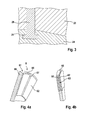
- FIG. 3 shows an example of an anchoring of the projecting ends of the legs 28 of the holding cage 22 in the support member 24.
- the support member 24 receiving recesses 29 having an undercut, in the corresponding projections of the legs 28 of the holding cage 25th engage and held there form-fitting.
- a locking connection between the legs 28 and the support member 24 is conceivable.
- cohesive connections such as adhesive bonds, be provided. In this way, the carrier element 2 and the bridge elements 27 of the holding cage 25 together form the recesses 26 for receiving the permanent magnets 23.
- thermal grease or the like may be provided as a thermal coupling means.
- FIGS. 4a and 4b different perspective views of another disc rotor 6 are shown.
- the further pancake 6 of FIGS. 4a and 4b has a rotor body 61 with a support member 66 which is formed with a magnetic receiving portion 63, are placed on the permanent magnets 62 in the axial direction.
- the magnet receiving area 63 is designed as recesses directed in the axial direction on one or both sides of the carrier element 66, so that adjacent permanent magnets 62 can be inserted or glued or otherwise secured therein in the circumferential direction.
- the carrier element 66 has a reduced thickness, wherein the remaining thickness of the carrier element 66 is preferably selected such that the heat dissipation from the permanent magnet 62 is greater than the heat generated by eddy currents during operation of the electric machine. Furthermore, it should be ensured that the thickness of the carrier element 66 is sufficient to ensure sufficient strength even when operating at the maximum speed.
- the carrier element 66 may be provided with a circumferential edge 65 on which the permanent magnets 62 can be supported outwardly.
- the permanent magnets 62 are arranged on both sides of the carrier element 66 in corresponding recesses of the magnetic receiving region 63, wherein the polarity directions can be carried out in the axial direction or in the circumferential direction to form rotor poles.
- the rotor body 61 may be provided without peripheral edge 65 in order to reduce the inertia of the disc rotor 6. In this case, reliable holding of the permanent magnets 62 by gluing or by other means of attachment is necessary.
- the permanent magnets 62 arranged in the receiving region may be surrounded, in particular encapsulated, by a sheath 67 made of an electrically non-conductive material, such as a plastic.
- the sheath 67 can serve to fix the permanent magnets 62 and protect them from external influences. Since the sheath 67 is electrically non-conductive, no eddy currents can arise, so that no additional heat is introduced into the permanent magnets 62.
- Heat generated in the pancake 6 can be dissipated via the rotor body 61, which is preferably made of a thermally highly conductive material, such as aluminum.
- the large contact surface of the permanent magnets 62 in the receiving area ensures good heat dissipation in the direction of the rotor shaft 4th
- FIGS. 5a and 5b are shown a plan view and a cross-sectional view through a pancake 7 of a further embodiment.
- a disk-shaped or annular rotor body 71 of the disk rotor 7 has a carrier element 77 which is provided with recesses 72 extending through in the axial direction A for receiving circumferentially adjacent permanent magnets 73.
- the support member 77 is formed of a thermally highly conductive material such as aluminum.
- the support member 77 may also be formed of a magnetically conductive sheet material.
- Radially outside of the recesses 72 is an axially out of the plane of the support member 77 projecting edge 75, which may be wholly or partially formed circumferentially. The wholly or partially circumferential edge may protrude axially in one or in both Richtugnen the disc rotor 7.
- the permanent magnets 73 may be a sheath 74 of an electrically and magnetically non-conductive (non-magnetic) material, such as plastic, may be provided which the permanent magnets 73 and / or the support member 77 completely or partially on at least one side of the support member 77 covers or surrounds. At least the sheath 74 may enclose only the radially inner edge and / or the radially outer edge of the permanent magnets 73 in order to hold them on the carrier element 77, wherein no sheath 74 is provided at a central region with respect to the radial direction.
- an electrically and magnetically non-conductive (non-magnetic) material such as plastic
- FIGS. 6a to 6c various possibilities of forming the rotor body 71 in a radially outer region of the rotor body 71 are shown.
- FIG. 12 is a cross-sectional view of the radially outer portion of the support member 77 with an outer portion segmented into projecting adjacent segments 76 which are alternately bent in mutually opposite axial directions to form a circumferential rim 75.
- the peripheral edge 75 is in contrast to the embodiment of FIGS. 4a and 4b not directly but via an intermediate region of the support member 77 with the permanent magnet 73 in thermal contact, so that in the support member 77 and the permanent magnet 73 resulting heat in the permanent magnet 73 to the segments 76 of the peripheral edge 75 can be derived.
- the segments 76 result in a rotation to a heat transfer from the support member 77 to the surrounding medium by turbulence of the surrounding medium, so that a reliable heat dissipation in the radial outward direction is ensured.
- FIG. 6b differs from the embodiment of Figure 6a in that the recesses 72 is formed with axially extending portions 79, in particular with bent edges, which make it possible to better hold the permanent magnets 72 and those with a larger area for a better Contact heat dissipation.
- FIG. 6c shows a carrier element 77 formed from two stacked sheets or discs, wherein at the radially outer edge of the carrier element 77 thus formed segments 76 are provided on both sheets, which are bent in mutually opposite directions.
- FIG. 7 shows a detail of a plan view of the support member 77 a structuring 78, such as a corrugation, the turbulence of the surrounding medium also allows along the side surface of the support member 77 and thereby improve the heat dissipation.
- a structuring 78 such as a corrugation
Landscapes
- Engineering & Computer Science (AREA)
- Power Engineering (AREA)
- Permanent Field Magnets Of Synchronous Machinery (AREA)
- Iron Core Of Rotating Electric Machines (AREA)
Applications Claiming Priority (1)
| Application Number | Priority Date | Filing Date | Title |
|---|---|---|---|
| DE102014213508.7A DE102014213508A1 (de) | 2014-07-11 | 2014-07-11 | Scheibenläufer für eine elektrische Maschine |
Publications (3)
| Publication Number | Publication Date |
|---|---|
| EP2975731A2 true EP2975731A2 (fr) | 2016-01-20 |
| EP2975731A3 EP2975731A3 (fr) | 2016-03-23 |
| EP2975731B1 EP2975731B1 (fr) | 2018-02-21 |
Family
ID=53054980
Family Applications (1)
| Application Number | Title | Priority Date | Filing Date |
|---|---|---|---|
| EP15167077.5A Active EP2975731B1 (fr) | 2014-07-11 | 2015-05-11 | Rotor a disque pour une machine electrique |
Country Status (2)
| Country | Link |
|---|---|
| EP (1) | EP2975731B1 (fr) |
| DE (1) | DE102014213508A1 (fr) |
Cited By (8)
| Publication number | Priority date | Publication date | Assignee | Title |
|---|---|---|---|---|
| DE102017206762A1 (de) | 2017-04-21 | 2018-10-25 | Efficient Energy Gmbh | Rotor für einen elektromotor mit wärmeabschirmender beschichtung und verfahren zur herstellung |
| DE102017206759A1 (de) | 2017-04-21 | 2018-10-25 | Efficient Energy Gmbh | Rotor für einen elektromotor mit speziell geformtem rückschlusselement und verfahren zur herstellung |
| DE102017214869A1 (de) | 2017-08-24 | 2019-02-28 | Efficient Energy Gmbh | Elektromotor mit verschiedenen Sternpunkten |
| CN111211630A (zh) * | 2020-01-21 | 2020-05-29 | 杭州中豪电动科技有限公司 | 盘式电机转子 |
| WO2020126015A1 (fr) | 2018-12-20 | 2020-06-25 | Efficient Energy Gmbh | Moteur électrique à différents points neutres |
| CN115425784A (zh) * | 2022-08-12 | 2022-12-02 | 华为数字能源技术有限公司 | 转子、盘式电机、电机驱动系统及车辆 |
| CN116054519A (zh) * | 2023-03-03 | 2023-05-02 | 上海盘毂动力科技股份有限公司 | 一种轴向磁场电机转子结构 |
| CN116231997A (zh) * | 2023-03-03 | 2023-06-06 | 上海盘毂动力科技股份有限公司 | 一种轴向磁场电机转子结构 |
Families Citing this family (5)
| Publication number | Priority date | Publication date | Assignee | Title |
|---|---|---|---|---|
| US11936256B2 (en) | 2020-04-24 | 2024-03-19 | Jacobi Motors, Llc | Flux-mnemonic permanent magnet synchronous machine and magnetizing a flux-mnemonic permanent magnet synchronous machine |
| DE102023113756A1 (de) * | 2023-05-25 | 2024-11-28 | Schaeffler Technologies AG & Co. KG | Rotor |
| DE102023115829A1 (de) * | 2023-06-16 | 2024-12-19 | Schaeffler Technologies AG & Co. KG | Rotor und elektrische Maschine |
| US12558980B2 (en) | 2023-11-09 | 2026-02-24 | Jacobi Motors, Llc | Integrated variable flux memory motor charger |
| US12614998B2 (en) | 2024-03-04 | 2026-04-28 | Jacobi Motors, Llc | System for multi-variable flux memory motor configuration |
Citations (1)
| Publication number | Priority date | Publication date | Assignee | Title |
|---|---|---|---|---|
| WO2009115247A1 (fr) | 2008-03-15 | 2009-09-24 | Rainer Marquardt | Entraînement direct à faible inertie et puissance volumique élevée |
Family Cites Families (4)
| Publication number | Priority date | Publication date | Assignee | Title |
|---|---|---|---|---|
| US4187441A (en) * | 1977-03-23 | 1980-02-05 | General Electric Company | High power density brushless dc motor |
| JP5130947B2 (ja) * | 2007-09-11 | 2013-01-30 | ダイキン工業株式会社 | アキシャルギャップ型回転電機及び回転駆動装置 |
| CN102292897B (zh) * | 2009-01-16 | 2014-04-02 | 科尔风力发电公司 | 用于轴向场装置的扇块式定子 |
| JP5786804B2 (ja) * | 2012-06-13 | 2015-09-30 | 株式会社デンソー | 回転電機の回転子及びその製造方法 |
-
2014
- 2014-07-11 DE DE102014213508.7A patent/DE102014213508A1/de not_active Withdrawn
-
2015
- 2015-05-11 EP EP15167077.5A patent/EP2975731B1/fr active Active
Patent Citations (1)
| Publication number | Priority date | Publication date | Assignee | Title |
|---|---|---|---|---|
| WO2009115247A1 (fr) | 2008-03-15 | 2009-09-24 | Rainer Marquardt | Entraînement direct à faible inertie et puissance volumique élevée |
Cited By (12)
| Publication number | Priority date | Publication date | Assignee | Title |
|---|---|---|---|---|
| DE102017206762A1 (de) | 2017-04-21 | 2018-10-25 | Efficient Energy Gmbh | Rotor für einen elektromotor mit wärmeabschirmender beschichtung und verfahren zur herstellung |
| WO2018193095A1 (fr) | 2017-04-21 | 2018-10-25 | Efficient Energy Gmbh | Rotor pour moteur électrique avec revêtement de protection thermique et son procédé de fabrication |
| DE102017206759A1 (de) | 2017-04-21 | 2018-10-25 | Efficient Energy Gmbh | Rotor für einen elektromotor mit speziell geformtem rückschlusselement und verfahren zur herstellung |
| WO2018193096A1 (fr) | 2017-04-21 | 2018-10-25 | Efficient Energy Gmbh | Rotor pour un moteur électrique à élément de retour de flux de forme spéciale et procédé de fabrication |
| DE102017214869A1 (de) | 2017-08-24 | 2019-02-28 | Efficient Energy Gmbh | Elektromotor mit verschiedenen Sternpunkten |
| DE102017214869B4 (de) | 2017-08-24 | 2026-04-16 | Vertiv Srl | Elektromotor mit verschiedenen Sternpunkten |
| WO2020126015A1 (fr) | 2018-12-20 | 2020-06-25 | Efficient Energy Gmbh | Moteur électrique à différents points neutres |
| US12046954B2 (en) | 2018-12-20 | 2024-07-23 | Vertiv S.R.L. | Electric motor with different star points |
| CN111211630A (zh) * | 2020-01-21 | 2020-05-29 | 杭州中豪电动科技有限公司 | 盘式电机转子 |
| CN115425784A (zh) * | 2022-08-12 | 2022-12-02 | 华为数字能源技术有限公司 | 转子、盘式电机、电机驱动系统及车辆 |
| CN116054519A (zh) * | 2023-03-03 | 2023-05-02 | 上海盘毂动力科技股份有限公司 | 一种轴向磁场电机转子结构 |
| CN116231997A (zh) * | 2023-03-03 | 2023-06-06 | 上海盘毂动力科技股份有限公司 | 一种轴向磁场电机转子结构 |
Also Published As
| Publication number | Publication date |
|---|---|
| EP2975731B1 (fr) | 2018-02-21 |
| EP2975731A3 (fr) | 2016-03-23 |
| DE102014213508A1 (de) | 2016-01-14 |
Similar Documents
| Publication | Publication Date | Title |
|---|---|---|
| EP2975731B1 (fr) | Rotor a disque pour une machine electrique | |
| DE102011121793B4 (de) | Elektromotor | |
| DE102009021703B4 (de) | Verbesserte Permanenterregte Synchronmaschine | |
| DE112013000536B4 (de) | Drehende Elektromaschine mit Hybriderregung | |
| DE112013000316B4 (de) | Drehende Elektromaschine mit Hybriderregung | |
| DE112010003859T5 (de) | Drehmotor vom Lundell-Typ | |
| DE102016203140A1 (de) | Statoranordnung für Axialflussmaschine | |
| DE112009002090T5 (de) | Drehende eletrische Maschine | |
| DE102012011444A1 (de) | Läufer und Motor | |
| EP3231070B1 (fr) | Moteur électrique à excitation permanente | |
| EP2770616A1 (fr) | Machine électrique avec stator séparé | |
| DE102011101730A1 (de) | Elektromotor | |
| DE102014203944A1 (de) | Läufereinheit für eine elektrische Maschine sowie elektrische Maschine | |
| DE102008064131A1 (de) | Elektrische Maschine | |
| EP2987223B1 (fr) | Rotor et procédé servant à fabriquer un rotor | |
| DE102014205034A1 (de) | Statoreinheit für eine elektrische Maschine sowie elektrische Maschine | |
| EP3646443B1 (fr) | Dispositif d'interconnection pour un stator pour une machine électrique rotative | |
| EP3012945B1 (fr) | Machine electrique dotee d'un carter | |
| DE112016004389T5 (de) | Rotierende elektrische maschine und herstellungsverfahren für eine rotierende elektrische maschine | |
| DE102014213452A1 (de) | Strömungsgekühlte elektrische Maschine mit einem Scheibenläufer | |
| DE102019218445A1 (de) | Elektromaschine mit Rotorkühlung und Kraftfahrzeug | |
| EP2866335A2 (fr) | Rotor avec anneaux de retenue pour machine à induction t procédé de fabrication de cellui-ci | |
| EP4084288B1 (fr) | Module de bobine pour une machine électrique | |
| EP1480317A2 (fr) | Machine électrique du flux magnétique axial | |
| DE102011079081A1 (de) | Lager mit Energieerzeugungseinheit |
Legal Events
| Date | Code | Title | Description |
|---|---|---|---|
| PUAI | Public reference made under article 153(3) epc to a published international application that has entered the european phase |
Free format text: ORIGINAL CODE: 0009012 |
|
| AK | Designated contracting states |
Kind code of ref document: A2 Designated state(s): AL AT BE BG CH CY CZ DE DK EE ES FI FR GB GR HR HU IE IS IT LI LT LU LV MC MK MT NL NO PL PT RO RS SE SI SK SM TR |
|
| AX | Request for extension of the european patent |
Extension state: BA ME |
|
| PUAL | Search report despatched |
Free format text: ORIGINAL CODE: 0009013 |
|
| AK | Designated contracting states |
Kind code of ref document: A3 Designated state(s): AL AT BE BG CH CY CZ DE DK EE ES FI FR GB GR HR HU IE IS IT LI LT LU LV MC MK MT NL NO PL PT RO RS SE SI SK SM TR |
|
| AX | Request for extension of the european patent |
Extension state: BA ME |
|
| RIC1 | Information provided on ipc code assigned before grant |
Ipc: H02K 9/22 20060101ALI20160218BHEP Ipc: H02K 21/24 20060101ALN20160218BHEP Ipc: H02K 1/27 20060101AFI20160218BHEP |
|
| 17P | Request for examination filed |
Effective date: 20160923 |
|
| RBV | Designated contracting states (corrected) |
Designated state(s): AL AT BE BG CH CY CZ DE DK EE ES FI FR GB GR HR HU IE IS IT LI LT LU LV MC MK MT NL NO PL PT RO RS SE SI SK SM TR |
|
| 17Q | First examination report despatched |
Effective date: 20170531 |
|
| GRAP | Despatch of communication of intention to grant a patent |
Free format text: ORIGINAL CODE: EPIDOSNIGR1 |
|
| RIC1 | Information provided on ipc code assigned before grant |
Ipc: H02K 1/27 20060101AFI20171010BHEP Ipc: H02K 9/22 20060101ALI20171010BHEP Ipc: H02K 21/24 20060101ALN20171010BHEP |
|
| RIC1 | Information provided on ipc code assigned before grant |
Ipc: H02K 9/22 20060101ALI20171017BHEP Ipc: H02K 21/24 20060101ALN20171017BHEP Ipc: H02K 1/27 20060101AFI20171017BHEP |
|
| INTG | Intention to grant announced |
Effective date: 20171113 |
|
| GRAS | Grant fee paid |
Free format text: ORIGINAL CODE: EPIDOSNIGR3 |
|
| GRAA | (expected) grant |
Free format text: ORIGINAL CODE: 0009210 |
|
| AK | Designated contracting states |
Kind code of ref document: B1 Designated state(s): AL AT BE BG CH CY CZ DE DK EE ES FI FR GB GR HR HU IE IS IT LI LT LU LV MC MK MT NL NO PL PT RO RS SE SI SK SM TR |
|
| REG | Reference to a national code |
Ref country code: GB Ref legal event code: FG4D Free format text: NOT ENGLISH |
|
| REG | Reference to a national code |
Ref country code: CH Ref legal event code: EP |
|
| REG | Reference to a national code |
Ref country code: AT Ref legal event code: REF Ref document number: 972727 Country of ref document: AT Kind code of ref document: T Effective date: 20180315 |
|
| REG | Reference to a national code |
Ref country code: IE Ref legal event code: FG4D Free format text: LANGUAGE OF EP DOCUMENT: GERMAN |
|
| REG | Reference to a national code |
Ref country code: DE Ref legal event code: R096 Ref document number: 502015003112 Country of ref document: DE |
|
| REG | Reference to a national code |
Ref country code: NL Ref legal event code: MP Effective date: 20180221 |
|
| REG | Reference to a national code |
Ref country code: LT Ref legal event code: MG4D |
|
| PG25 | Lapsed in a contracting state [announced via postgrant information from national office to epo] |
Ref country code: NL Free format text: LAPSE BECAUSE OF FAILURE TO SUBMIT A TRANSLATION OF THE DESCRIPTION OR TO PAY THE FEE WITHIN THE PRESCRIBED TIME-LIMIT Effective date: 20180221 Ref country code: HR Free format text: LAPSE BECAUSE OF FAILURE TO SUBMIT A TRANSLATION OF THE DESCRIPTION OR TO PAY THE FEE WITHIN THE PRESCRIBED TIME-LIMIT Effective date: 20180221 Ref country code: CY Free format text: LAPSE BECAUSE OF FAILURE TO SUBMIT A TRANSLATION OF THE DESCRIPTION OR TO PAY THE FEE WITHIN THE PRESCRIBED TIME-LIMIT Effective date: 20180221 Ref country code: FI Free format text: LAPSE BECAUSE OF FAILURE TO SUBMIT A TRANSLATION OF THE DESCRIPTION OR TO PAY THE FEE WITHIN THE PRESCRIBED TIME-LIMIT Effective date: 20180221 Ref country code: NO Free format text: LAPSE BECAUSE OF FAILURE TO SUBMIT A TRANSLATION OF THE DESCRIPTION OR TO PAY THE FEE WITHIN THE PRESCRIBED TIME-LIMIT Effective date: 20180521 Ref country code: LT Free format text: LAPSE BECAUSE OF FAILURE TO SUBMIT A TRANSLATION OF THE DESCRIPTION OR TO PAY THE FEE WITHIN THE PRESCRIBED TIME-LIMIT Effective date: 20180221 Ref country code: ES Free format text: LAPSE BECAUSE OF FAILURE TO SUBMIT A TRANSLATION OF THE DESCRIPTION OR TO PAY THE FEE WITHIN THE PRESCRIBED TIME-LIMIT Effective date: 20180221 |
|
| PG25 | Lapsed in a contracting state [announced via postgrant information from national office to epo] |
Ref country code: SE Free format text: LAPSE BECAUSE OF FAILURE TO SUBMIT A TRANSLATION OF THE DESCRIPTION OR TO PAY THE FEE WITHIN THE PRESCRIBED TIME-LIMIT Effective date: 20180221 Ref country code: LV Free format text: LAPSE BECAUSE OF FAILURE TO SUBMIT A TRANSLATION OF THE DESCRIPTION OR TO PAY THE FEE WITHIN THE PRESCRIBED TIME-LIMIT Effective date: 20180221 Ref country code: RS Free format text: LAPSE BECAUSE OF FAILURE TO SUBMIT A TRANSLATION OF THE DESCRIPTION OR TO PAY THE FEE WITHIN THE PRESCRIBED TIME-LIMIT Effective date: 20180221 Ref country code: BG Free format text: LAPSE BECAUSE OF FAILURE TO SUBMIT A TRANSLATION OF THE DESCRIPTION OR TO PAY THE FEE WITHIN THE PRESCRIBED TIME-LIMIT Effective date: 20180521 Ref country code: GR Free format text: LAPSE BECAUSE OF FAILURE TO SUBMIT A TRANSLATION OF THE DESCRIPTION OR TO PAY THE FEE WITHIN THE PRESCRIBED TIME-LIMIT Effective date: 20180522 |
|
| PG25 | Lapsed in a contracting state [announced via postgrant information from national office to epo] |
Ref country code: MT Free format text: LAPSE BECAUSE OF FAILURE TO SUBMIT A TRANSLATION OF THE DESCRIPTION OR TO PAY THE FEE WITHIN THE PRESCRIBED TIME-LIMIT Effective date: 20180221 |
|
| PG25 | Lapsed in a contracting state [announced via postgrant information from national office to epo] |
Ref country code: RO Free format text: LAPSE BECAUSE OF FAILURE TO SUBMIT A TRANSLATION OF THE DESCRIPTION OR TO PAY THE FEE WITHIN THE PRESCRIBED TIME-LIMIT Effective date: 20180221 Ref country code: IT Free format text: LAPSE BECAUSE OF FAILURE TO SUBMIT A TRANSLATION OF THE DESCRIPTION OR TO PAY THE FEE WITHIN THE PRESCRIBED TIME-LIMIT Effective date: 20180221 Ref country code: EE Free format text: LAPSE BECAUSE OF FAILURE TO SUBMIT A TRANSLATION OF THE DESCRIPTION OR TO PAY THE FEE WITHIN THE PRESCRIBED TIME-LIMIT Effective date: 20180221 Ref country code: PL Free format text: LAPSE BECAUSE OF FAILURE TO SUBMIT A TRANSLATION OF THE DESCRIPTION OR TO PAY THE FEE WITHIN THE PRESCRIBED TIME-LIMIT Effective date: 20180221 Ref country code: AL Free format text: LAPSE BECAUSE OF FAILURE TO SUBMIT A TRANSLATION OF THE DESCRIPTION OR TO PAY THE FEE WITHIN THE PRESCRIBED TIME-LIMIT Effective date: 20180221 |
|
| REG | Reference to a national code |
Ref country code: DE Ref legal event code: R097 Ref document number: 502015003112 Country of ref document: DE |
|
| PG25 | Lapsed in a contracting state [announced via postgrant information from national office to epo] |
Ref country code: SM Free format text: LAPSE BECAUSE OF FAILURE TO SUBMIT A TRANSLATION OF THE DESCRIPTION OR TO PAY THE FEE WITHIN THE PRESCRIBED TIME-LIMIT Effective date: 20180221 Ref country code: DK Free format text: LAPSE BECAUSE OF FAILURE TO SUBMIT A TRANSLATION OF THE DESCRIPTION OR TO PAY THE FEE WITHIN THE PRESCRIBED TIME-LIMIT Effective date: 20180221 Ref country code: SK Free format text: LAPSE BECAUSE OF FAILURE TO SUBMIT A TRANSLATION OF THE DESCRIPTION OR TO PAY THE FEE WITHIN THE PRESCRIBED TIME-LIMIT Effective date: 20180221 Ref country code: CZ Free format text: LAPSE BECAUSE OF FAILURE TO SUBMIT A TRANSLATION OF THE DESCRIPTION OR TO PAY THE FEE WITHIN THE PRESCRIBED TIME-LIMIT Effective date: 20180221 |
|
| REG | Reference to a national code |
Ref country code: CH Ref legal event code: PL |
|
| PLBE | No opposition filed within time limit |
Free format text: ORIGINAL CODE: 0009261 |
|
| STAA | Information on the status of an ep patent application or granted ep patent |
Free format text: STATUS: NO OPPOSITION FILED WITHIN TIME LIMIT |
|
| 26N | No opposition filed |
Effective date: 20181122 |
|
| REG | Reference to a national code |
Ref country code: BE Ref legal event code: MM Effective date: 20180531 |
|
| PG25 | Lapsed in a contracting state [announced via postgrant information from national office to epo] |
Ref country code: MC Free format text: LAPSE BECAUSE OF FAILURE TO SUBMIT A TRANSLATION OF THE DESCRIPTION OR TO PAY THE FEE WITHIN THE PRESCRIBED TIME-LIMIT Effective date: 20180221 |
|
| REG | Reference to a national code |
Ref country code: IE Ref legal event code: MM4A |
|
| PG25 | Lapsed in a contracting state [announced via postgrant information from national office to epo] |
Ref country code: SI Free format text: LAPSE BECAUSE OF FAILURE TO SUBMIT A TRANSLATION OF THE DESCRIPTION OR TO PAY THE FEE WITHIN THE PRESCRIBED TIME-LIMIT Effective date: 20180221 Ref country code: CH Free format text: LAPSE BECAUSE OF NON-PAYMENT OF DUE FEES Effective date: 20180531 Ref country code: LI Free format text: LAPSE BECAUSE OF NON-PAYMENT OF DUE FEES Effective date: 20180531 |
|
| PG25 | Lapsed in a contracting state [announced via postgrant information from national office to epo] |
Ref country code: LU Free format text: LAPSE BECAUSE OF NON-PAYMENT OF DUE FEES Effective date: 20180511 |
|
| PG25 | Lapsed in a contracting state [announced via postgrant information from national office to epo] |
Ref country code: FR Free format text: LAPSE BECAUSE OF NON-PAYMENT OF DUE FEES Effective date: 20180531 Ref country code: IE Free format text: LAPSE BECAUSE OF NON-PAYMENT OF DUE FEES Effective date: 20180511 |
|
| PG25 | Lapsed in a contracting state [announced via postgrant information from national office to epo] |
Ref country code: BE Free format text: LAPSE BECAUSE OF NON-PAYMENT OF DUE FEES Effective date: 20180531 |
|
| GBPC | Gb: european patent ceased through non-payment of renewal fee |
Effective date: 20190511 |
|
| PG25 | Lapsed in a contracting state [announced via postgrant information from national office to epo] |
Ref country code: TR Free format text: LAPSE BECAUSE OF FAILURE TO SUBMIT A TRANSLATION OF THE DESCRIPTION OR TO PAY THE FEE WITHIN THE PRESCRIBED TIME-LIMIT Effective date: 20180221 |
|
| PG25 | Lapsed in a contracting state [announced via postgrant information from national office to epo] |
Ref country code: GB Free format text: LAPSE BECAUSE OF NON-PAYMENT OF DUE FEES Effective date: 20190511 |
|
| PG25 | Lapsed in a contracting state [announced via postgrant information from national office to epo] |
Ref country code: PT Free format text: LAPSE BECAUSE OF FAILURE TO SUBMIT A TRANSLATION OF THE DESCRIPTION OR TO PAY THE FEE WITHIN THE PRESCRIBED TIME-LIMIT Effective date: 20180221 |
|
| PG25 | Lapsed in a contracting state [announced via postgrant information from national office to epo] |
Ref country code: HU Free format text: LAPSE BECAUSE OF FAILURE TO SUBMIT A TRANSLATION OF THE DESCRIPTION OR TO PAY THE FEE WITHIN THE PRESCRIBED TIME-LIMIT; INVALID AB INITIO Effective date: 20150511 Ref country code: MK Free format text: LAPSE BECAUSE OF NON-PAYMENT OF DUE FEES Effective date: 20180221 |
|
| PG25 | Lapsed in a contracting state [announced via postgrant information from national office to epo] |
Ref country code: IS Free format text: LAPSE BECAUSE OF FAILURE TO SUBMIT A TRANSLATION OF THE DESCRIPTION OR TO PAY THE FEE WITHIN THE PRESCRIBED TIME-LIMIT Effective date: 20180621 |
|
| REG | Reference to a national code |
Ref country code: AT Ref legal event code: MM01 Ref document number: 972727 Country of ref document: AT Kind code of ref document: T Effective date: 20200511 |
|
| PG25 | Lapsed in a contracting state [announced via postgrant information from national office to epo] |
Ref country code: AT Free format text: LAPSE BECAUSE OF NON-PAYMENT OF DUE FEES Effective date: 20200511 |
|
| PGFP | Annual fee paid to national office [announced via postgrant information from national office to epo] |
Ref country code: DE Payment date: 20250716 Year of fee payment: 11 |