EP2976128B1 - Tube pour circuit extracorporel avec double connecteur - Google Patents
Tube pour circuit extracorporel avec double connecteur Download PDFInfo
- Publication number
- EP2976128B1 EP2976128B1 EP14712252.7A EP14712252A EP2976128B1 EP 2976128 B1 EP2976128 B1 EP 2976128B1 EP 14712252 A EP14712252 A EP 14712252A EP 2976128 B1 EP2976128 B1 EP 2976128B1
- Authority
- EP
- European Patent Office
- Prior art keywords
- double connector
- channel
- extra
- circuit
- insert
- Prior art date
- Legal status (The legal status is an assumption and is not a legal conclusion. Google has not performed a legal analysis and makes no representation as to the accuracy of the status listed.)
- Active
Links
Images


Classifications
-
- A—HUMAN NECESSITIES
- A61—MEDICAL OR VETERINARY SCIENCE; HYGIENE
- A61M—DEVICES FOR INTRODUCING MEDIA INTO, OR ONTO, THE BODY; DEVICES FOR TRANSDUCING BODY MEDIA OR FOR TAKING MEDIA FROM THE BODY; DEVICES FOR PRODUCING OR ENDING SLEEP OR STUPOR
- A61M1/00—Suction or pumping devices for medical purposes; Devices for carrying-off, for treatment of, or for carrying-over, body-liquids; Drainage systems
- A61M1/36—Other treatment of blood in a by-pass of the natural circulatory system, e.g. temperature adaptation, irradiation ; Extra-corporeal blood circuits
- A61M1/3621—Extra-corporeal blood circuits
- A61M1/367—Circuit parts not covered by the preceding subgroups of group A61M1/3621
-
- A—HUMAN NECESSITIES
- A61—MEDICAL OR VETERINARY SCIENCE; HYGIENE
- A61M—DEVICES FOR INTRODUCING MEDIA INTO, OR ONTO, THE BODY; DEVICES FOR TRANSDUCING BODY MEDIA OR FOR TAKING MEDIA FROM THE BODY; DEVICES FOR PRODUCING OR ENDING SLEEP OR STUPOR
- A61M39/00—Tubes, tube connectors, tube couplings, valves, access sites or the like, specially adapted for medical use
- A61M39/10—Tube connectors; Tube couplings
- A61M39/12—Tube connectors; Tube couplings for joining a flexible tube to a rigid attachment
-
- F—MECHANICAL ENGINEERING; LIGHTING; HEATING; WEAPONS; BLASTING
- F16—ENGINEERING ELEMENTS AND UNITS; GENERAL MEASURES FOR PRODUCING AND MAINTAINING EFFECTIVE FUNCTIONING OF MACHINES OR INSTALLATIONS; THERMAL INSULATION IN GENERAL
- F16L—PIPES; JOINTS OR FITTINGS FOR PIPES; SUPPORTS FOR PIPES, CABLES OR PROTECTIVE TUBING; MEANS FOR THERMAL INSULATION IN GENERAL
- F16L25/00—Construction or details of pipe joints not provided for in, or of interest apart from, groups F16L13/00 - F16L23/00
- F16L25/0018—Abutment joints
-
- F—MECHANICAL ENGINEERING; LIGHTING; HEATING; WEAPONS; BLASTING
- F16—ENGINEERING ELEMENTS AND UNITS; GENERAL MEASURES FOR PRODUCING AND MAINTAINING EFFECTIVE FUNCTIONING OF MACHINES OR INSTALLATIONS; THERMAL INSULATION IN GENERAL
- F16L—PIPES; JOINTS OR FITTINGS FOR PIPES; SUPPORTS FOR PIPES, CABLES OR PROTECTIVE TUBING; MEANS FOR THERMAL INSULATION IN GENERAL
- F16L37/00—Couplings of the quick-acting type
- F16L37/008—Couplings of the quick-acting type for branching pipes; for joining pipes to walls
-
- A—HUMAN NECESSITIES
- A61—MEDICAL OR VETERINARY SCIENCE; HYGIENE
- A61M—DEVICES FOR INTRODUCING MEDIA INTO, OR ONTO, THE BODY; DEVICES FOR TRANSDUCING BODY MEDIA OR FOR TAKING MEDIA FROM THE BODY; DEVICES FOR PRODUCING OR ENDING SLEEP OR STUPOR
- A61M39/00—Tubes, tube connectors, tube couplings, valves, access sites or the like, specially adapted for medical use
- A61M39/10—Tube connectors; Tube couplings
- A61M2039/1072—Tube connectors; Tube couplings with a septum present in the connector
-
- A—HUMAN NECESSITIES
- A61—MEDICAL OR VETERINARY SCIENCE; HYGIENE
- A61M—DEVICES FOR INTRODUCING MEDIA INTO, OR ONTO, THE BODY; DEVICES FOR TRANSDUCING BODY MEDIA OR FOR TAKING MEDIA FROM THE BODY; DEVICES FOR PRODUCING OR ENDING SLEEP OR STUPOR
- A61M39/00—Tubes, tube connectors, tube couplings, valves, access sites or the like, specially adapted for medical use
- A61M39/10—Tube connectors; Tube couplings
- A61M2039/1077—Adapters, e.g. couplings adapting a connector to one or several other connectors
-
- A—HUMAN NECESSITIES
- A61—MEDICAL OR VETERINARY SCIENCE; HYGIENE
- A61M—DEVICES FOR INTRODUCING MEDIA INTO, OR ONTO, THE BODY; DEVICES FOR TRANSDUCING BODY MEDIA OR FOR TAKING MEDIA FROM THE BODY; DEVICES FOR PRODUCING OR ENDING SLEEP OR STUPOR
- A61M5/00—Devices for bringing media into the body in a subcutaneous, intra-vascular or intramuscular way; Accessories therefor, e.g. filling or cleaning devices, arm-rests
- A61M5/14—Infusion devices, e.g. infusing by gravity; Blood infusion; Accessories therefor
- A61M5/142—Pressure infusion, e.g. using pumps
- A61M5/14212—Pumping with an aspiration and an expulsion action
- A61M5/14232—Roller pumps
-
- F—MECHANICAL ENGINEERING; LIGHTING; HEATING; WEAPONS; BLASTING
- F04—POSITIVE - DISPLACEMENT MACHINES FOR LIQUIDS; PUMPS FOR LIQUIDS OR ELASTIC FLUIDS
- F04B—POSITIVE-DISPLACEMENT MACHINES FOR LIQUIDS; PUMPS
- F04B43/00—Machines, pumps, or pumping installations having flexible working members
- F04B43/0009—Special features
- F04B43/0054—Special features particularities of the flexible members
- F04B43/0072—Special features particularities of the flexible members of tubular flexible members
Definitions
- the invention relates to a circuit for extra-corporeal circulation and in particular to the tubular insert intended to co-operate with a peristaltic pump and the double connector included in the tubular insert.
- peristaltic pumps comprising a stator and a rotor between which a flexible tube is inserted.
- the rotor of the pump comprises rollers, usually two rollers, suitable for pressing the flexible tube against the stator.
- the combined action of the pressure exerted by the rollers and the rotation imparted by the rotor causes displacement of the liquid between the two rollers inside the tube.
- the subsequent and constant displacement of portions of liquid produces in a known manner pumping of the liquid along the circuit.
- the machine which performs the therapeutic treatment usually comprises special sensors.
- each circuit for the extra-corporeal circulation with a tubular insert intended to co-operate with the peristaltic pump, a pressure chamber suitable for co-operating with the pressure sensor and a series of so-called ports which allow the connection of other containers or the safe piercing by means of a syringe needle.
- a particularly effective tubular insert has been developed by the Applicant and is widely used in order to facilitate connection of the tube to the peristaltic pump, for example at the time of preparation of the machine for a haemodialysis treatment.
- Such a tubular insert is described, for example, in the international patent application filed by the same Applicant and published under number WO 2005/111424 .
- the insert comprises a double connector and a loop formed with a tube section of suitable length and is commonly called an " ⁇ insert” owing to its shape.
- this type of insert has overall an ⁇ shape since the inlet portion and the outlet portion of the double connector overlap each other.
- inlet portion is understood as meaning the portion which is intended to be connected to the circuit section coming from the patient
- output portion is understood as meaning the portion which is intended to be connected to the circuit section directed towards the machine, for example towards the dialysis filter.
- the inlet portion and the outlet portion intersect, in different planes, inside the double connector.
- the loop of the ⁇ insert comprises a wide curve which extends along a cylindrical helix which defines an axis intended, during use, to coincide with the axis of rotation of the peristaltic pump. Since the cylindrical helix has a pitch which is decidedly smaller than the curve, by way of a first approximation, it may be considered that the curve lies in a plane and therefore describes an arc of a circumference.
- the pressure chamber also known as “pressure dome” is instead designed to create an interface between the circuit and the pressure sensor present on the treatment machine.
- the pressure chamber as well as the entire circuit of which it forms part, are disposable articles.
- the pressure chamber usually comprises a housing with an inlet connector and outlet connector respectively connected to the circuit.
- an elastomeric membrane closes one side of the chamber and is shaped so as to be able to come into contact with the pressure sensor.
- the elastomeric membrane has a considerable degree of elasticity which allows it to transmit to the sensor the pressure present inside the circuit and the associated variations.
- the pressure chamber which is situated along a tube of the circuit, must be fixed to the machine so that the membrane rests firmly on the pressure sensor.
- the pressure chamber is fixed in position by means of a snap-engaging lever which ensures stable positioning during the entire treatment.
- the ⁇ insert is retained inside the machine by means of a snap-engagement connection provided between the double connector and the respective seat formed in the machine.
- the snap-engagement connection must have a sufficiently easy action to allow any member of staff to easily insert the double connector inside the corresponding seat so as to be able to prepare the machine for therapeutic treatment.
- This operation is usually performed with the circuit at room temperature (generally ranging between 20° and 25°C), while during operation of the machine the circuit heats up until it reaches, in its operating steady condition, a temperature close to body temperature (and therefore in the region of 37°C).
- This difference in temperature results in a difference in the mechanical characteristics of the thermoplastic polymer which forms the double connector, in particular heating of the polymer results in a reduction in the rigidity thereof.
- the interference produced by an easy snap-engaging action at room temperature may therefore be insufficient to hold the connector firmly in position at body temperature.
- the peristaltic pump acts on the ⁇ insert as though the loop of the latter were describing an arc of a circumference rather than a section of a cylindrical helix.
- This approximation is more than valid for the purposes of circulation within the circuit, but is less so from the point of view of the stresses which the rotor rollers impart to the ⁇ insert.
- the forces generated by the rotor rollers contain components parallel to the axis X of rotation instead of being completely contained within the plane perpendicular thereto.
- a rotation of the pump rotor generates periodic stresses on the ⁇ insert which tend to move it in the direction of X and therefore causes the double connector to come out of its seat. This effect, which is negligible in the cold state, may become extremely problematic when the double connector loses its rigidity owing to the operating temperature.
- a first negative consequence is that of increasing the time and the volumes of liquid required for the so-called priming, i.e. the operation of filling the circuit with liquid (whether it be blood, physiological solution, replacement liquid, or the like) so as to expel the air or other foreign fluids and make the machine operative.
- priming i.e. the operation of filling the circuit with liquid (whether it be blood, physiological solution, replacement liquid, or the like) so as to expel the air or other foreign fluids and make the machine operative.
- haemodialysis is here considered as an example. Since the entire circuit is disposable, it is disposed of after only a single treatment. It is to be considered that, according to a paper published by Michael J. Lysaght, in 2002 the worldwide dialysis population already exceeded one million and had a growth rate of 7% per year. According to some projections, the dialysis patients would have doubled within 2010. Each one of these patients may need three or four treatments per week. Thus it will be clear for the skilled person that the overall amount of material used in the single circuit is not an insignificant item when assessing the sustainability over a long period of time of haemodialysis, both in terms of the environmental impact and in terms of cost for the sanitary services.
- WO 2007/056363 A2 discloses a tubular medical flow set comprising a pressure chamber connected in flow-through relation to fluid flow tubing of the set.
- the pressure sensing chamber defines a movable, flexible, impermeable diaphragm dividing the chamber into two separate compartments.
- the fluid flow tubing communicates with one of the compartments and is isolated from the other compartments.
- EP 2 383 004 A1 discloses a membrane for a pressure dome suitable for cooperate with a pressure sensor.
- the membrane comprises a resilient circular wall suitable for closing one side of the pressure dome so as to define a partition between the inside of the pressure dome and the outside, and a resilient circular rim suitable for being joined to a main body of the pressure dome.
- WO 01/32256 A1 discloses a combined arterial and venous blood tubing set for transport of blood between a patient and a blood processing unit.
- the set comprises an arterial set component comprising arterial tubing having an arterial patient connector at one end and an arterial unit connector at the other end, and a venous set component comprising venous tubing having a venous patient connector at one end and a venous unit connector at the other end.
- the arterial and venous patient connectors and the arterial and venous unit connectors are respectively substantially and releasably directly connected to each other, whereby said arterial and venous set components cooperate to form a loop.
- the object of the present invention is therefore to solve at least partially the problems mentioned in connection with the circuits for extra-corporeal circulation, and in particular in connection with the tubular inserts, of the known type.
- a task of the present invention is to provide a double connector and a tubular insert for extra-corporeal circuits which ensures stable positioning inside the peristaltic pump.
- a task of the present invention is to provide a double connector and a tubular insert for extra-corporeal circuits which is able to reduce the overall dimensions of the extra-corporeal circuit of which it forms part.
- a task of the present invention is to provide a tubular insert and associated extra-corporeal circuit which have a low-cost.
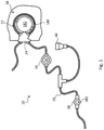
- the reference number 20 denotes in its entirety an extra-corporeal circuit of the type commonly used in treatments which require an extra-corporeal circulation, such as haemodialysis, haemofiltration and the like.
- the extra-corporeal circuit 20 comprises a tubular insert 22 intended to connect the extra-corporeal circuit 20 to a peristaltic pump 18.
- the tubular insert 22 comprises a double connector 24 and a loop 26 formed by a tube section 28 of suitable length.
- the double connector 24 comprises:
- the double connector 24 also comprises a piercible insert 38 arranged along one of the two channels 30 or 32.
- the insert 38 is of the type which can be pierced by the needle of a syringe, typically in order to supply or remove a liquid into/from the underlying channel 30 or 32.
- the insert 38 may be arranged along the first channel 30 (as shown in Figures 8 to 16 ), along the second channel (solution not shown) or an insert 38 may be arranged on each of the two channels 30 and 32 (solution not shown).
- the double connector 24 also comprises a port 40 arranged along one of the two channels 30 or 32.
- the port 40 is of the type suitable for connection to an external container in order to supply/remove a liquid into/from the channel 30 or 32.
- the container may be, for example, a bottle, a bag, a phial or the like.
- the port 40 may be arranged along the first channel 30 (as shown in Figure 15 ), along the second channel (solution not shown) or a port 40 may be arranged on each of the two channels 30 and 32 (solution not shown).
- the double connector 24 allows the extra-corporeal circuit 20 to have overall an extremely compact design.
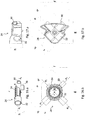
- the double connector 24 also comprises the pressure chamber 34, which in the solution according to the prior art, was formed as a separate component arranged along the circuit.
- the double connector 24 may be appreciated more fully when one considers the fact that, in the particular embodiments shown in Figures 16 , it encloses within it also the pressure chamber 34 and the piercible insert 38.
- the double connector 24 according to the invention comprising the pressure chamber 34
- the double connector 24 may in turn be kept firmly in position by means of the snap-engaging lever which, in a manner known per se, keeps the pressure chamber 34 pressed against the pressure sensor 16 of the machine.
- the service personnel does not have to perform any additional operation during preparation of the machine; on the contrary, it is required to fix only one component (the connector comprising the pressure chamber) instead of the two separate components as in the known solution (the connector and the pressure chamber).
- the fixing force remains constant during treatment and in particular is independent of the operating temperature and the mechanical characteristics of the polymer which forms the double connector 24. It should be also noted how, owing to fixing of the double connector 24 by means of the snap-engaging lever, it may be kept firmly in position even though the forces applied by the rotor 182 onto the loop 26 have non-zero components directed along the axis X.
- the compactness characteristics of the double connector 24 according to the invention are accentuated even further in the embodiments which also comprise one or more piercible inserts 38 and/or one or more ports 40. These components also, in the solution according to the prior art, were distributed along the extra-corporeal circuit 20, thus making it longer.
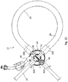
- the tubular insert 22 has overall an ⁇ shape since, in the double connector 24, the first channel 30 and second channel 32 overlap each other.
- the first channel 30 is the inlet channel, intended to be connected to the circuit section coming from the patient
- the second channel 32 is the outlet channel 36, intended to be connected to the circuit section directed towards the treatment machine, for example towards the dialysis filter.
- the first channel 30 and the second channel 32 intersect, in different planes, inside the double connector 24.
- the loop 26 comprises a wide curve 24 which extends along a cylindrical helix and is connected to the connector 24 by means of two substantially straight tube segments.
- the cylindrical helix along which the curve of the loop 26 extends defines an axis intended, during use, to coincide with the rotation axis of the rotor 182 of the peristaltic pump 18. Both these axes are indicated below by a single reference letter X since, during use, they coincide along a single axis.
- the cylindrical helix has a pitch p which is decidedly smaller than the diameter D such that, according to a first approximation, it may be considered that the curve lies in a plane and therefore describes an arc of a circumference. It may be considered, for example, that, according to a first preferred embodiment, the diameter D of the cylindrical helix is about 50 mm, while the pitch p is only about 6 mm.
- the loop 26 is intended to be inserted between the stator 180 and the rotor 182 of the peristaltic pump 18.
- the curve extends preferably along an arc ⁇ with an amplitude greater than 180°, so as to be able to co-operate effectively with the rotor 182, the rollers of which are generally two in number and arranged at a distance of 180° from each other.
- the curve extends along an arc which has an amplitude of about 270°.
- the axis a 1 of the first channel 30 and the axis a 2 of the second channel 32 lie in the same plane.
- the two axes a 1 and a 2 are offset relative to each other (as shown in Figure 16.a ). In any case the geometrical definitions given above and relating to the straight line r and to the plane ⁇ are nevertheless valid.
- the possibility of providing the double connector 24 according to the invention with a coplanar arrangement of the axes a 1 and a 2 is the result of the integration of the pressure chamber 34 inside the first channel 30.
- this pressure chamber 34 has a main axis, indicated here by a 1 , which is common to the inlet connector and the outlet connector.
- the longitudinal profile of the duct defined by the pressure chamber 34 comprises a deviation from the axis a 1 towards the membrane 36 and then back to towards the axis a 1 .
- This path which is optimized in order to achieve precise measurement of the pressure by means of the membrane 36, allows the second channel 32 to intersect the first channel 30, while maintaining the respective axes a 2 and a 1 in the same plane without the need of designedly deviating the flow. It should be noted, in fact, that any deviation of the flow of this type results in a loss of head which reduces the overall efficiency of the extra-corporeal circuit. It is therefore extremely advantageous to make use of the flow deviation already present in the pressure chamber 34 for other reasons.
- a double connector 24 may solve the abovementioned problems arising from the approximation which occurs in the peristaltic pump 18 with the connectors of the known type.
- the fact that the loop 26 in reality lies in one plane in fact neutralizes the components along the axis X of the stresses applied by the rollers of the rotor 182 onto the tubular insert 22. The neutralization of these stresses therefore has the effect of making more stable positioning of the insert 22 in the peristaltic pump 18, and in particular positioning of the double connector 24 in its seat on the machine.
- both the channels 30 and 32 of the double connector 24 comprise an end 300 and 320 suitable for connection to a flexible tube 28 intended to form the loop 26 designed to be seated between the stator 180 and the rotor 182 of the peristaltic pump 18.
- the present invention relates to the tubular insert 22 intended to connect the extra-corporeal circuit 20 to the peristaltic pump 18.
- the tubular insert 22 according to the invention comprises a double connector 24 of the type described above and the flexible tube portion 28 which forms the loop 26 is intended to be seated between the stator 180 and the rotor 182 of the peristaltic pump 18.
- both the channels 30 and 32 of the double connector 24 comprise an end 302 and 322 suitable for connection to a flexible tube 28 intended to form a portion of the extra-corporeal circuit 20.
- a first portion of the extra-corporeal circuit 20 is designed to connect the patient to the tubular insert 22, while a second portion of the extra-corporeal circuit 20 is designed to connect the tubular insert 22 to the machine component which performs the treatment, for example the dialysis filter.
- the present invention relates to the entire extra-corporeal circuit 20 designed to be connected to the peristaltic pump 18.
- the extra-corporeal circuit 20 according to the invention comprises the tubular insert 22 of the type described above.
- the tube 28 of the tubular insert may be made of silicone, plasticized PVC (e.g. plasticized with DOP (dioctylphthalate) or with TOTM (trioctyl-trimellitate)), PP, or another elastomer suitable for medical use.
- plasticized PVC e.g. plasticized with DOP (dioctylphthalate) or with TOTM (trioctyl-trimellitate)
- PP polypropylene
- another elastomer suitable for medical use elastomer suitable for medical use.
- the membrane 36 comprises an elastic circular wall 360 and a circular rim 364.
- the elastic circular wall 360 is designed to close one side of the pressure chamber 34 so as to define a division between the interior of the pressure chamber 34 and the exterior.
- the circular rim 364 is designed to be connected to the body of the pressure chamber 34.
- the elastic circular wall 360 when there is no difference in the pressures acting on the inner side 361 and on the outer side 362, respectively, has an outwardly convex form.
- the inner side 361 is that side which, during use, is wetted by the physiological liquid
- the outer side 362 is that side which, during use, comes into contact against the pressure sensor 16 of the machine.
- the membrane 36 may also have a double curvature.
- the elastic circular wall 360 may assume the form of a dome, for example a dome forming part of a sphere or a different solid of rotation.
- the distance between the outermost point of the dome and the plane ⁇ containing the base circumference is between 1% in 2% of the diameter of the base circumference of the dome.
- the membrane 36 is preferably made as one piece.
- the rim 364 is preferably formed integrally and as one piece with the wall 360. Even more preferably, the rim 364 and the wall 360 are formed by means of injection-moulding of a single material.
- the membrane 36 may be made, in a manner known per se, of thermoplastic elastomer, silicone or other elastomers suitable for contact with the physiological fluids.
- the outwardly convex shape of the membrane 36 eliminates any risk of air bubbles remaining trapped between the membrane itself and the pressure sensor 16 when the double connector 24 is arranged in position. In fact, the contact between the membrane 36 and the pressure sensor 16 occurs gradually, starting from the centre (i.e. from the outermost point of the wall 360) and progressing gradually towards the periphery. In this way, the air is gradually expelled externally.
- the convex shape of the membrane 36 has the effect that, following relaxation due to ageing of the elastomer or the operating conditions to which the membrane 36 is subject, the wall 360 is able to maintain its functionality. Any relaxation will result in the worst of cases in a reduction in the convexity, but it is unlikely that it will be manage to eliminate it and/or invert the curvature of the wall 360 until it becomes concave.
- the body of the double connector 24 defines a seat 42 for stably housing the membrane 36; the seat is in particular configured to receive the rim 364 of the membrane 36.
- the body of the double connector 24 is preferably produced, in a manner known per se, by means of injection-moulding of a polymer which is sufficiently rigid and suitable for contact with physiological fluids.
- Polymers which are suitable for this type of use may be for example: polycarbonate (PC), polypropylene (PP), polyethylene (PE), polystyrene (PS), polyvinyl chloride (PVC), polyethylene terephthalate (PET), polybutylene terephthalate (PBT), acrylonitrile-butadiene-styrene (ABS) and copolyesters.
- the seat 42 is defined by an edge 420 and by an inner wall 422.
- the edge 420 allows the membrane 36 to be fixed inside the seat 42.
- the double connector 24 is preferably produced with the edge 420 formed as a cylindrical wall (see in particular Figures 11 and 13 ).
- This system for fixing the membrane 36 obtained by means of deformation of the edge 420 is known as beading.
- Deformation of the edge 420 may be obtained, in a manner known per se in the sector of polymer processing, by means of heat application, ultrasound or spin welding.
- Beading is carried out in such a way that the pressure chamber 34 as a whole is hermetically sealed, with the exception, obviously, of the openings which form the inlet and outlet of the first channel 30.
- the joint between the membrane 36 and the body of the double connector 24 must prevent the physiological liquid, which is intended to occupy the pressure chamber 34, from infiltrating between the seat 42 and the membrane 36 and therefore from escaping externally.
- the membrane 36 is fixed to the body of the double connector 24 by means of a rigid ring, in a manner known per se for example by the pressure chamber shown in Figure 8 .
- the connection between the rigid ring and the body of the double connector 24 may be of the snap-engaging type, screw/female thread type, interference-fit type, or the like.
- the membrane 36 and the ring are made separately, while in other embodiments they are made by means of two-component injection moulding. This therefore produces, in a manner known per se, a single part made of two different materials.
- the body of the double connector 24 defines a seat 44 for stably housing the plug 380 and thus defining the piercible insert 38.
- the seat 44 is defined by an edge 440 which allows the plug 380 to be fixed inside the seat 44.
- the double connector 24 is preferably produced with the edge 440 formed as a cylindrical wall (see in particular Figures 12 and 13 ).
- said fixing by means of beading may be obtained, in a manner known per se, by means of heat application, ultrasound or spin welding. Beading is carried out in such a way that the piercible insert 38 as a whole is hermetically sealed, with the exception, obviously, of the opening in the channel. In other words, the joint between the plug 380 and the body of the double connector 24 must prevent the physiological liquid from infiltrating between the seat 44 and the plug 380 and therefore from being able to escape externally.
- the plug 380 is fixed to the body of the double connector 24 by means of a rigid ring, in a manner known per se.
- the connection between the rigid ring and the body of the double connector 24 may be of the snap-engaging type, screw/female thread type, interference-fit type, or the like.
- the plug 380 and the ring are made separately, while in other embodiments they are made by means of two-component injection moulding.
- the double connector 24, the tubular insert 22 and the extra-corporeal circuit 20 according to the invention are able to solve at least partially the drawbacks mentioned above in relation to the prior art.
- the double connector and the tubular insert described above are suitable for giving the extra-corporeal circuit a particular compactness.
- Such compactness allows reducing the costs and the environmental impact of the disposable extra-corporeal circuits.
- the extra-corporeal circuit according to the invention allows easier manufacture and sterilization steps.
Landscapes
- Health & Medical Sciences (AREA)
- Engineering & Computer Science (AREA)
- Heart & Thoracic Surgery (AREA)
- General Engineering & Computer Science (AREA)
- Anesthesiology (AREA)
- Veterinary Medicine (AREA)
- Hematology (AREA)
- Life Sciences & Earth Sciences (AREA)
- Animal Behavior & Ethology (AREA)
- General Health & Medical Sciences (AREA)
- Public Health (AREA)
- Biomedical Technology (AREA)
- Pulmonology (AREA)
- Vascular Medicine (AREA)
- Mechanical Engineering (AREA)
- Cardiology (AREA)
- External Artificial Organs (AREA)
- Infusion, Injection, And Reservoir Apparatuses (AREA)
- Reciprocating Pumps (AREA)
Claims (9)
- Connecteur double (24) destiné à un insert tubulaire (22) destiné à relier un circuit extracorporel (20) à une pompe péristaltique (18), le connecteur double (24) comprenant :un premier canal (30) ayant un axe longitudinal α 1 ;un second canal (32) ayant un axe longitudinal α 2 non parallèle à α 1 ;une chambre de pression (34) prévue le long du premier canal (30) et adaptée pour coopérer avec un capteur de pression (16), la chambre de pression étant fermée, sur le côté opposé au second canal (32), par une membrane (36) qui s'étend principalement sur un plan π sensiblement parallèle aux deux axes α 1 et α 2 ;caractérisé en ce qu'une ligne droite r, qui passe par les deux axes α 1 et α 2 et est perpendiculaire à ceux-ci, traverse la membrane (36) ;et en ce que l'axe α 1 du premier canal (30) et l'axe α 2 du second canal (32) se trouvent sur le même plan.
- Connecteur double (24) selon la revendication 1, comprenant en outre un insert perçable (38) prévu le long de l'un des deux canaux (30, 32), l'insert (38) étant perçable avec une aiguille de façon à fournir ou retirer un liquide au/du canal (30, 32).
- Connecteur double (24) selon la revendication 1 ou 2, comprenant en outre un orifice (40) prévu le long de l'un des deux canaux (30, 32), l'orifice (40) étant adapté pour être relié à un contenant de façon à fournir ou à retirer un liquide au/du canal (30, 32).
- Connecteur double (24) selon l'une quelconque des revendications précédentes, dans lequel les deux canaux (30, 32) comprennent une extrémité (300, 320) adaptée pour être reliée à un tube flexible (28) destiné à former une boucle (26) conçue pour être placée entre le stator (180) et le rotor (182) d'une pompe péristaltique (18).
- Connecteur double (24) selon l'une quelconque des revendications précédentes, dans lequel les deux canaux (30, 32) comprennent une extrémité (302, 322) adaptée pour être reliée à un tube flexible (28) destiné à former une partie du circuit extracorporel (20).
- Connecteur double (24) selon l'une quelconque des revendications précédentes, dans lequel la membrane (36) comprend une paroi circulaire élastique (360) qui, lorsqu'il n'y a aucune différence de pressions qui agissent sur le côté interne (361) et sur le côté externe (362), respectivement, possède une force convexe vers l'extérieur.
- Connecteur double (24) selon l'une quelconque des revendications précédentes, dans lequel la membrane (36) et/ou un embout (380) de l'insert perçable (38) sont retenus à l'intérieur des sièges respectifs (42, 44) en roulant un bord (420, 440) du siège (42, 44).
- Insert tubulaire (22) destiné à connecter un circuit extra-corporel (20) à une pompe péristaltique (18), comprenant un connecteur double (24) selon l'une quelconque des revendications précédentes et une section de tube (28) qui forme une boucle (26) destinée à être placée entre le stator (180) et le rotor (182) d'une pompe péristaltique (18).
- Circuit extracorporel (20) conçu pour être relié à une pompe péristaltique (18), ledit circuit (20) comprenant un insert tubulaire (22) selon la revendication précédente.
Priority Applications (3)
| Application Number | Priority Date | Filing Date | Title |
|---|---|---|---|
| PL14712252T PL2976128T3 (pl) | 2013-03-20 | 2014-03-18 | Rurka do obwodu krążenia pozaustrojowego z łącznikiem podwójnym |
| EP14712252.7A EP2976128B1 (fr) | 2013-03-20 | 2014-03-18 | Tube pour circuit extracorporel avec double connecteur |
| EP19201643.4A EP3628366A1 (fr) | 2013-03-20 | 2014-03-18 | Tube pour circuit extracorporel |
Applications Claiming Priority (3)
| Application Number | Priority Date | Filing Date | Title |
|---|---|---|---|
| EP13160216.1A EP2781234A1 (fr) | 2013-03-20 | 2013-03-20 | Tube pour circuit extracorporel avec double connecteur |
| PCT/EP2014/055392 WO2014147061A1 (fr) | 2013-03-20 | 2014-03-18 | Tube pour circuit extracorporel à double raccord |
| EP14712252.7A EP2976128B1 (fr) | 2013-03-20 | 2014-03-18 | Tube pour circuit extracorporel avec double connecteur |
Related Child Applications (2)
| Application Number | Title | Priority Date | Filing Date |
|---|---|---|---|
| EP19201643.4A Division-Into EP3628366A1 (fr) | 2013-03-20 | 2014-03-18 | Tube pour circuit extracorporel |
| EP19201643.4A Division EP3628366A1 (fr) | 2013-03-20 | 2014-03-18 | Tube pour circuit extracorporel |
Publications (2)
| Publication Number | Publication Date |
|---|---|
| EP2976128A1 EP2976128A1 (fr) | 2016-01-27 |
| EP2976128B1 true EP2976128B1 (fr) | 2020-03-04 |
Family
ID=47915504
Family Applications (3)
| Application Number | Title | Priority Date | Filing Date |
|---|---|---|---|
| EP13160216.1A Withdrawn EP2781234A1 (fr) | 2013-03-20 | 2013-03-20 | Tube pour circuit extracorporel avec double connecteur |
| EP14712252.7A Active EP2976128B1 (fr) | 2013-03-20 | 2014-03-18 | Tube pour circuit extracorporel avec double connecteur |
| EP19201643.4A Withdrawn EP3628366A1 (fr) | 2013-03-20 | 2014-03-18 | Tube pour circuit extracorporel |
Family Applications Before (1)
| Application Number | Title | Priority Date | Filing Date |
|---|---|---|---|
| EP13160216.1A Withdrawn EP2781234A1 (fr) | 2013-03-20 | 2013-03-20 | Tube pour circuit extracorporel avec double connecteur |
Family Applications After (1)
| Application Number | Title | Priority Date | Filing Date |
|---|---|---|---|
| EP19201643.4A Withdrawn EP3628366A1 (fr) | 2013-03-20 | 2014-03-18 | Tube pour circuit extracorporel |
Country Status (12)
| Country | Link |
|---|---|
| US (1) | US10226565B2 (fr) |
| EP (3) | EP2781234A1 (fr) |
| JP (1) | JP6523248B2 (fr) |
| KR (1) | KR20150135232A (fr) |
| CN (1) | CN105263563B (fr) |
| AU (1) | AU2014234425B2 (fr) |
| BR (1) | BR112015024107A2 (fr) |
| CA (1) | CA2904469A1 (fr) |
| EA (1) | EA030106B1 (fr) |
| ES (1) | ES2795928T3 (fr) |
| PL (1) | PL2976128T3 (fr) |
| WO (1) | WO2014147061A1 (fr) |
Families Citing this family (20)
| Publication number | Priority date | Publication date | Assignee | Title |
|---|---|---|---|---|
| GB201421964D0 (en) * | 2014-12-10 | 2015-01-21 | Hodges & Drake Design Ltd | Peristaltic pumps |
| CN105561412B (zh) * | 2016-02-02 | 2018-02-23 | 丁以群 | 心脏辅助装置 |
| DE102016101911A1 (de) * | 2016-02-03 | 2017-08-03 | B. Braun Avitum Ag | Medizinische Kupplung und medizinisches System mit einer medizinischen Kupplung |
| DE102016013334B3 (de) * | 2016-11-10 | 2018-04-05 | Fresenius Medical Care Deutschland Gmbh | Medizinisches Gerät mit einem Verbindungsstück für die Herstellung einer Flüssigkeitsverbindung zwischen flüssigkeitsführenden Leitungen |
| DE102017103857A1 (de) * | 2017-02-24 | 2018-08-30 | B. Braun Avitum Ag | Flüssigkeitspumpe |
| DE102018121872A1 (de) | 2018-09-07 | 2020-03-12 | Fresenius Medical Care Deutschland Gmbh | Peristaltische Pumpe |
| DE102018121903A1 (de) | 2018-09-07 | 2020-03-12 | Fresenius Medical Care Deutschland Gmbh | Peristaltische Pumpe |
| DE102018121868A1 (de) | 2018-09-07 | 2020-03-12 | Fresenius Medical Care Deutschland Gmbh | Peristaltische Pumpe |
| US11540777B2 (en) * | 2019-04-02 | 2023-01-03 | Baxter International Inc. | Removable fluid sensor in an administration set |
| WO2021094145A1 (fr) | 2019-11-12 | 2021-05-20 | Fresenius Medical Care Deutschland Gmbh | Systèmes de traitement du sang |
| CA3160967A1 (fr) | 2019-11-12 | 2021-05-20 | Fresenius Medical Care Deutschland Gmbh | Systemes de traitement du sang |
| WO2021094144A1 (fr) | 2019-11-12 | 2021-05-20 | Fresenius Medical Care Deutschland Gmbh | Systèmes de traitement du sang |
| CN114728116A (zh) | 2019-11-12 | 2022-07-08 | 费森尤斯医疗护理德国有限责任公司 | 血液治疗系统 |
| WO2021094140A1 (fr) | 2019-11-12 | 2021-05-20 | Fresenius Medical Care Deutschland Gmbh | Systèmes de traitement du sang |
| CN114728110A (zh) | 2019-11-12 | 2022-07-08 | 费森尤斯医疗护理德国有限责任公司 | 血液治疗系统 |
| US12558468B2 (en) | 2019-12-12 | 2026-02-24 | Fresenius Medical Care Holdings, Inc. | Blood treatment systems |
| EP4438102A1 (fr) | 2023-03-31 | 2024-10-02 | Fresenius Medical Care Deutschland GmbH | Raccord pour raccorder un segment de tuyau de pompe à un lit de pompe d'une pompe péristaltique |
| EP4497454A1 (fr) | 2023-07-24 | 2025-01-29 | Fresenius Medical Care Deutschland GmbH | Pompe et dispositif de mesure de pression |
| EP4497453A1 (fr) | 2023-07-24 | 2025-01-29 | Fresenius Medical Care Deutschland GmbH | Raccord de tuyaux |
| EP4717287A1 (fr) | 2024-09-30 | 2026-04-01 | Fresenius Medical Care Deutschland GmbH | Raccord pour positionner un segment de tuyau de pompe |
Family Cites Families (12)
| Publication number | Priority date | Publication date | Assignee | Title |
|---|---|---|---|---|
| DE59405906D1 (de) * | 1994-02-16 | 1998-06-10 | Stoeckert Instr Gmbh | Schlauchfixierungsvorrichtung für Rollenpumpen |
| US5661245A (en) * | 1995-07-14 | 1997-08-26 | Sensym, Incorporated | Force sensor assembly with integrated rigid, movable interface for transferring force to a responsive medium |
| US6517508B1 (en) * | 1999-11-03 | 2003-02-11 | Dsu Medical Corporation | Set for blood processing |
| ES2356026T3 (es) * | 2004-05-14 | 2011-04-04 | Fresenius Medical Care Deutschland Gmbh | Bomba de rodillos. |
| EP1658869A1 (fr) | 2004-11-17 | 2006-05-24 | Fresenius Medical Care Deutschland GmbH | Membrane, boîtier d'un capteur de pression et capteur de pression |
| US7124921B1 (en) * | 2005-04-12 | 2006-10-24 | John Hubbell | Modular personal carrying system |
| US7331217B2 (en) * | 2005-08-08 | 2008-02-19 | O'sullivan Raymond | Re-usable main drain testing method and apparatus |
| US8092414B2 (en) * | 2005-11-09 | 2012-01-10 | Nxstage Medical, Inc. | Diaphragm pressure pod for medical fluids |
| EP2383004A1 (fr) * | 2010-04-30 | 2011-11-02 | Fresenius Medical Care Deutschland GmbH | Membrane pour dôme de pression |
| EP2514451A1 (fr) | 2011-04-21 | 2012-10-24 | SIS-TER S.p.A. | Insert tubulaire pour circuit extracorporel |
| TWI564543B (zh) * | 2011-06-30 | 2017-01-01 | 瑪波微影Ip公司 | 電容測量系統、測量電路以及微影蝕刻機器 |
| DE102011108787A1 (de) * | 2011-07-29 | 2013-01-31 | Fresenius Medical Care Deutschland Gmbh | Medizinischer Port, Blutschlauch zur Verwendung bei einer extrakorporalen Blutbehandlung sowie medizinische Behandlungsvorrichtung |
-
2013
- 2013-03-20 EP EP13160216.1A patent/EP2781234A1/fr not_active Withdrawn
-
2014
- 2014-03-18 JP JP2016503636A patent/JP6523248B2/ja active Active
- 2014-03-18 EP EP14712252.7A patent/EP2976128B1/fr active Active
- 2014-03-18 US US14/769,897 patent/US10226565B2/en active Active
- 2014-03-18 CN CN201480016540.7A patent/CN105263563B/zh active Active
- 2014-03-18 BR BR112015024107A patent/BR112015024107A2/pt not_active Application Discontinuation
- 2014-03-18 EP EP19201643.4A patent/EP3628366A1/fr not_active Withdrawn
- 2014-03-18 WO PCT/EP2014/055392 patent/WO2014147061A1/fr not_active Ceased
- 2014-03-18 AU AU2014234425A patent/AU2014234425B2/en active Active
- 2014-03-18 PL PL14712252T patent/PL2976128T3/pl unknown
- 2014-03-18 ES ES14712252T patent/ES2795928T3/es active Active
- 2014-03-18 EA EA201591852A patent/EA030106B1/ru not_active IP Right Cessation
- 2014-03-18 CA CA2904469A patent/CA2904469A1/fr not_active Abandoned
- 2014-03-18 KR KR1020157022496A patent/KR20150135232A/ko not_active Abandoned
Non-Patent Citations (1)
| Title |
|---|
| None * |
Also Published As
| Publication number | Publication date |
|---|---|
| JP2016512773A (ja) | 2016-05-09 |
| AU2014234425B2 (en) | 2018-08-09 |
| EA201591852A1 (ru) | 2016-01-29 |
| JP6523248B2 (ja) | 2019-05-29 |
| EP2781234A1 (fr) | 2014-09-24 |
| PL2976128T3 (pl) | 2020-08-24 |
| US10226565B2 (en) | 2019-03-12 |
| BR112015024107A2 (pt) | 2017-07-18 |
| EP3628366A1 (fr) | 2020-04-01 |
| CN105263563A (zh) | 2016-01-20 |
| EA030106B1 (ru) | 2018-06-29 |
| HK1216865A1 (en) | 2016-12-09 |
| KR20150135232A (ko) | 2015-12-02 |
| CA2904469A1 (fr) | 2014-09-25 |
| US20160000988A1 (en) | 2016-01-07 |
| WO2014147061A1 (fr) | 2014-09-25 |
| EP2976128A1 (fr) | 2016-01-27 |
| CN105263563B (zh) | 2017-12-15 |
| ES2795928T3 (es) | 2020-11-25 |
| AU2014234425A1 (en) | 2015-10-15 |
Similar Documents
| Publication | Publication Date | Title |
|---|---|---|
| EP2976128B1 (fr) | Tube pour circuit extracorporel avec double connecteur | |
| CN106573095B (zh) | 用于体外血液透析机的压力输出装置 | |
| EP3305344A1 (fr) | Dispositif de détection de pression de liquide médical | |
| US20140094740A1 (en) | Dialysis connector and cap compatible with gas sterilization | |
| EP3762061B1 (fr) | Tube médical tolérant au pliage et à la compression | |
| HK1216865B (en) | Tube for extra-corporeal circuit with double connector | |
| US20250018100A1 (en) | Peritoneal dialysis system having a patient line filter | |
| EP4259232B1 (fr) | Ensemble collecteur pour appareil de dialyse péritonéale et appareil de dialyse péritonéale comprenant ledit ensemble collecteur | |
| AU2022413407A1 (en) | Peritoneal dialysis system having a patient line filter | |
| US20250001060A1 (en) | Peritoneal dialysis system having a patient line filter | |
| EP4259231B1 (fr) | Ensemble collecteur pour appareil de dialyse péritonéale et appareil de dialyse péritonéale comprenant ledit ensemble collecteur |
Legal Events
| Date | Code | Title | Description |
|---|---|---|---|
| PUAI | Public reference made under article 153(3) epc to a published international application that has entered the european phase |
Free format text: ORIGINAL CODE: 0009012 |
|
| 17P | Request for examination filed |
Effective date: 20150723 |
|
| AK | Designated contracting states |
Kind code of ref document: A1 Designated state(s): AL AT BE BG CH CY CZ DE DK EE ES FI FR GB GR HR HU IE IS IT LI LT LU LV MC MK MT NL NO PL PT RO RS SE SI SK SM TR |
|
| AX | Request for extension of the european patent |
Extension state: BA ME |
|
| DAX | Request for extension of the european patent (deleted) | ||
| REG | Reference to a national code |
Ref country code: HK Ref legal event code: DE Ref document number: 1216865 Country of ref document: HK |
|
| STAA | Information on the status of an ep patent application or granted ep patent |
Free format text: STATUS: EXAMINATION IS IN PROGRESS |
|
| 17Q | First examination report despatched |
Effective date: 20180522 |
|
| GRAP | Despatch of communication of intention to grant a patent |
Free format text: ORIGINAL CODE: EPIDOSNIGR1 |
|
| STAA | Information on the status of an ep patent application or granted ep patent |
Free format text: STATUS: GRANT OF PATENT IS INTENDED |
|
| INTG | Intention to grant announced |
Effective date: 20190108 |
|
| RIN1 | Information on inventor provided before grant (corrected) |
Inventor name: FINI, MASSIMO Inventor name: REITER, REINHOLD Inventor name: WEHMEYER, WOLFGANG |
|
| GRAJ | Information related to disapproval of communication of intention to grant by the applicant or resumption of examination proceedings by the epo deleted |
Free format text: ORIGINAL CODE: EPIDOSDIGR1 |
|
| STAA | Information on the status of an ep patent application or granted ep patent |
Free format text: STATUS: EXAMINATION IS IN PROGRESS |
|
| INTC | Intention to grant announced (deleted) | ||
| GRAP | Despatch of communication of intention to grant a patent |
Free format text: ORIGINAL CODE: EPIDOSNIGR1 |
|
| STAA | Information on the status of an ep patent application or granted ep patent |
Free format text: STATUS: GRANT OF PATENT IS INTENDED |
|
| INTG | Intention to grant announced |
Effective date: 20191002 |
|
| GRAS | Grant fee paid |
Free format text: ORIGINAL CODE: EPIDOSNIGR3 |
|
| GRAA | (expected) grant |
Free format text: ORIGINAL CODE: 0009210 |
|
| STAA | Information on the status of an ep patent application or granted ep patent |
Free format text: STATUS: THE PATENT HAS BEEN GRANTED |
|
| AK | Designated contracting states |
Kind code of ref document: B1 Designated state(s): AL AT BE BG CH CY CZ DE DK EE ES FI FR GB GR HR HU IE IS IT LI LT LU LV MC MK MT NL NO PL PT RO RS SE SI SK SM TR |
|
| REG | Reference to a national code |
Ref country code: GB Ref legal event code: FG4D |
|
| REG | Reference to a national code |
Ref country code: CH Ref legal event code: EP |
|
| REG | Reference to a national code |
Ref country code: AT Ref legal event code: REF Ref document number: 1239685 Country of ref document: AT Kind code of ref document: T Effective date: 20200315 |
|
| REG | Reference to a national code |
Ref country code: DE Ref legal event code: R096 Ref document number: 602014061825 Country of ref document: DE |
|
| REG | Reference to a national code |
Ref country code: IE Ref legal event code: FG4D |
|
| REG | Reference to a national code |
Ref country code: CH Ref legal event code: NV Representative=s name: PATENTANWAELTE SCHAAD, BALASS, MENZL AND PARTN, CH |
|
| REG | Reference to a national code |
Ref country code: SE Ref legal event code: TRGR |
|
| REG | Reference to a national code |
Ref country code: NL Ref legal event code: FP |
|
| PG25 | Lapsed in a contracting state [announced via postgrant information from national office to epo] |
Ref country code: RS Free format text: LAPSE BECAUSE OF FAILURE TO SUBMIT A TRANSLATION OF THE DESCRIPTION OR TO PAY THE FEE WITHIN THE PRESCRIBED TIME-LIMIT Effective date: 20200304 Ref country code: FI Free format text: LAPSE BECAUSE OF FAILURE TO SUBMIT A TRANSLATION OF THE DESCRIPTION OR TO PAY THE FEE WITHIN THE PRESCRIBED TIME-LIMIT Effective date: 20200304 Ref country code: NO Free format text: LAPSE BECAUSE OF FAILURE TO SUBMIT A TRANSLATION OF THE DESCRIPTION OR TO PAY THE FEE WITHIN THE PRESCRIBED TIME-LIMIT Effective date: 20200604 |
|
| PG25 | Lapsed in a contracting state [announced via postgrant information from national office to epo] |
Ref country code: BG Free format text: LAPSE BECAUSE OF FAILURE TO SUBMIT A TRANSLATION OF THE DESCRIPTION OR TO PAY THE FEE WITHIN THE PRESCRIBED TIME-LIMIT Effective date: 20200604 Ref country code: HR Free format text: LAPSE BECAUSE OF FAILURE TO SUBMIT A TRANSLATION OF THE DESCRIPTION OR TO PAY THE FEE WITHIN THE PRESCRIBED TIME-LIMIT Effective date: 20200304 Ref country code: GR Free format text: LAPSE BECAUSE OF FAILURE TO SUBMIT A TRANSLATION OF THE DESCRIPTION OR TO PAY THE FEE WITHIN THE PRESCRIBED TIME-LIMIT Effective date: 20200605 Ref country code: LV Free format text: LAPSE BECAUSE OF FAILURE TO SUBMIT A TRANSLATION OF THE DESCRIPTION OR TO PAY THE FEE WITHIN THE PRESCRIBED TIME-LIMIT Effective date: 20200304 |
|
| REG | Reference to a national code |
Ref country code: LT Ref legal event code: MG4D |
|
| PG25 | Lapsed in a contracting state [announced via postgrant information from national office to epo] |
Ref country code: SM Free format text: LAPSE BECAUSE OF FAILURE TO SUBMIT A TRANSLATION OF THE DESCRIPTION OR TO PAY THE FEE WITHIN THE PRESCRIBED TIME-LIMIT Effective date: 20200304 Ref country code: EE Free format text: LAPSE BECAUSE OF FAILURE TO SUBMIT A TRANSLATION OF THE DESCRIPTION OR TO PAY THE FEE WITHIN THE PRESCRIBED TIME-LIMIT Effective date: 20200304 Ref country code: PT Free format text: LAPSE BECAUSE OF FAILURE TO SUBMIT A TRANSLATION OF THE DESCRIPTION OR TO PAY THE FEE WITHIN THE PRESCRIBED TIME-LIMIT Effective date: 20200729 Ref country code: RO Free format text: LAPSE BECAUSE OF FAILURE TO SUBMIT A TRANSLATION OF THE DESCRIPTION OR TO PAY THE FEE WITHIN THE PRESCRIBED TIME-LIMIT Effective date: 20200304 Ref country code: CZ Free format text: LAPSE BECAUSE OF FAILURE TO SUBMIT A TRANSLATION OF THE DESCRIPTION OR TO PAY THE FEE WITHIN THE PRESCRIBED TIME-LIMIT Effective date: 20200304 Ref country code: IS Free format text: LAPSE BECAUSE OF FAILURE TO SUBMIT A TRANSLATION OF THE DESCRIPTION OR TO PAY THE FEE WITHIN THE PRESCRIBED TIME-LIMIT Effective date: 20200704 Ref country code: SK Free format text: LAPSE BECAUSE OF FAILURE TO SUBMIT A TRANSLATION OF THE DESCRIPTION OR TO PAY THE FEE WITHIN THE PRESCRIBED TIME-LIMIT Effective date: 20200304 Ref country code: LT Free format text: LAPSE BECAUSE OF FAILURE TO SUBMIT A TRANSLATION OF THE DESCRIPTION OR TO PAY THE FEE WITHIN THE PRESCRIBED TIME-LIMIT Effective date: 20200304 |
|
| REG | Reference to a national code |
Ref country code: AT Ref legal event code: MK05 Ref document number: 1239685 Country of ref document: AT Kind code of ref document: T Effective date: 20200304 |
|
| REG | Reference to a national code |
Ref country code: ES Ref legal event code: FG2A Ref document number: 2795928 Country of ref document: ES Kind code of ref document: T3 Effective date: 20201125 |
|
| REG | Reference to a national code |
Ref country code: DE Ref legal event code: R097 Ref document number: 602014061825 Country of ref document: DE |
|
| REG | Reference to a national code |
Ref country code: BE Ref legal event code: MM Effective date: 20200331 |
|
| PG25 | Lapsed in a contracting state [announced via postgrant information from national office to epo] |
Ref country code: MC Free format text: LAPSE BECAUSE OF FAILURE TO SUBMIT A TRANSLATION OF THE DESCRIPTION OR TO PAY THE FEE WITHIN THE PRESCRIBED TIME-LIMIT Effective date: 20200304 Ref country code: LU Free format text: LAPSE BECAUSE OF NON-PAYMENT OF DUE FEES Effective date: 20200318 |
|
| PLBE | No opposition filed within time limit |
Free format text: ORIGINAL CODE: 0009261 |
|
| STAA | Information on the status of an ep patent application or granted ep patent |
Free format text: STATUS: NO OPPOSITION FILED WITHIN TIME LIMIT |
|
| PG25 | Lapsed in a contracting state [announced via postgrant information from national office to epo] |
Ref country code: IE Free format text: LAPSE BECAUSE OF NON-PAYMENT OF DUE FEES Effective date: 20200318 Ref country code: AT Free format text: LAPSE BECAUSE OF FAILURE TO SUBMIT A TRANSLATION OF THE DESCRIPTION OR TO PAY THE FEE WITHIN THE PRESCRIBED TIME-LIMIT Effective date: 20200304 Ref country code: DK Free format text: LAPSE BECAUSE OF FAILURE TO SUBMIT A TRANSLATION OF THE DESCRIPTION OR TO PAY THE FEE WITHIN THE PRESCRIBED TIME-LIMIT Effective date: 20200304 |
|
| 26N | No opposition filed |
Effective date: 20201207 |
|
| PG25 | Lapsed in a contracting state [announced via postgrant information from national office to epo] |
Ref country code: BE Free format text: LAPSE BECAUSE OF NON-PAYMENT OF DUE FEES Effective date: 20200331 Ref country code: SI Free format text: LAPSE BECAUSE OF FAILURE TO SUBMIT A TRANSLATION OF THE DESCRIPTION OR TO PAY THE FEE WITHIN THE PRESCRIBED TIME-LIMIT Effective date: 20200304 |
|
| PG25 | Lapsed in a contracting state [announced via postgrant information from national office to epo] |
Ref country code: MT Free format text: LAPSE BECAUSE OF FAILURE TO SUBMIT A TRANSLATION OF THE DESCRIPTION OR TO PAY THE FEE WITHIN THE PRESCRIBED TIME-LIMIT Effective date: 20200304 Ref country code: CY Free format text: LAPSE BECAUSE OF FAILURE TO SUBMIT A TRANSLATION OF THE DESCRIPTION OR TO PAY THE FEE WITHIN THE PRESCRIBED TIME-LIMIT Effective date: 20200304 |
|
| PG25 | Lapsed in a contracting state [announced via postgrant information from national office to epo] |
Ref country code: MK Free format text: LAPSE BECAUSE OF FAILURE TO SUBMIT A TRANSLATION OF THE DESCRIPTION OR TO PAY THE FEE WITHIN THE PRESCRIBED TIME-LIMIT Effective date: 20200304 Ref country code: AL Free format text: LAPSE BECAUSE OF FAILURE TO SUBMIT A TRANSLATION OF THE DESCRIPTION OR TO PAY THE FEE WITHIN THE PRESCRIBED TIME-LIMIT Effective date: 20200304 |
|
| P01 | Opt-out of the competence of the unified patent court (upc) registered |
Effective date: 20230602 |
|
| PGFP | Annual fee paid to national office [announced via postgrant information from national office to epo] |
Ref country code: ES Payment date: 20250401 Year of fee payment: 12 |
|
| PGFP | Annual fee paid to national office [announced via postgrant information from national office to epo] |
Ref country code: CH Payment date: 20250401 Year of fee payment: 12 |
|
| PGFP | Annual fee paid to national office [announced via postgrant information from national office to epo] |
Ref country code: NL Payment date: 20260219 Year of fee payment: 13 |
|
| REG | Reference to a national code |
Ref country code: CH Ref legal event code: U11 Free format text: ST27 STATUS EVENT CODE: U-0-0-U10-U11 (AS PROVIDED BY THE NATIONAL OFFICE) Effective date: 20260401 |
|
| PGFP | Annual fee paid to national office [announced via postgrant information from national office to epo] |
Ref country code: SE Payment date: 20260219 Year of fee payment: 13 |
|
| PGFP | Annual fee paid to national office [announced via postgrant information from national office to epo] |
Ref country code: GB Payment date: 20260220 Year of fee payment: 13 |
|
| PGFP | Annual fee paid to national office [announced via postgrant information from national office to epo] |
Ref country code: DE Payment date: 20260219 Year of fee payment: 13 |
|
| PGFP | Annual fee paid to national office [announced via postgrant information from national office to epo] |
Ref country code: IT Payment date: 20260219 Year of fee payment: 13 |
|
| PGFP | Annual fee paid to national office [announced via postgrant information from national office to epo] |
Ref country code: FR Payment date: 20260219 Year of fee payment: 13 |
|
| PGFP | Annual fee paid to national office [announced via postgrant information from national office to epo] |
Ref country code: TR Payment date: 20260224 Year of fee payment: 13 |
|
| PGFP | Annual fee paid to national office [announced via postgrant information from national office to epo] |
Ref country code: PL Payment date: 20260220 Year of fee payment: 13 |