EP2976166B1 - Endstück zum einsetzen in ein zufür-/saugrohr und zufür-/saugvorrichtung mit solch einem endstück - Google Patents
Endstück zum einsetzen in ein zufür-/saugrohr und zufür-/saugvorrichtung mit solch einem endstück Download PDFInfo
- Publication number
- EP2976166B1 EP2976166B1 EP14716879.3A EP14716879A EP2976166B1 EP 2976166 B1 EP2976166 B1 EP 2976166B1 EP 14716879 A EP14716879 A EP 14716879A EP 2976166 B1 EP2976166 B1 EP 2976166B1
- Authority
- EP
- European Patent Office
- Prior art keywords
- piece
- pipe
- nozzle
- supply
- container
- Prior art date
- Legal status (The legal status is an assumption and is not a legal conclusion. Google has not performed a legal analysis and makes no representation as to the accuracy of the status listed.)
- Not-in-force
Links
Images



Classifications
-
- B—PERFORMING OPERATIONS; TRANSPORTING
- B08—CLEANING
- B08B—CLEANING IN GENERAL; PREVENTION OF FOULING IN GENERAL
- B08B9/00—Cleaning hollow articles by methods or apparatus specially adapted thereto
- B08B9/08—Cleaning containers, e.g. tanks
- B08B9/093—Cleaning containers, e.g. tanks by the force of jets or sprays
- B08B9/0936—Cleaning containers, e.g. tanks by the force of jets or sprays using rotating jets
-
- B—PERFORMING OPERATIONS; TRANSPORTING
- B05—SPRAYING OR ATOMISING IN GENERAL; APPLYING FLUENT MATERIALS TO SURFACES, IN GENERAL
- B05B—SPRAYING APPARATUS; ATOMISING APPARATUS; NOZZLES
- B05B3/00—Spraying or sprinkling apparatus with moving outlet elements or moving deflecting elements
- B05B3/02—Spraying or sprinkling apparatus with moving outlet elements or moving deflecting elements with rotating elements
- B05B3/04—Spraying or sprinkling apparatus with moving outlet elements or moving deflecting elements with rotating elements driven by the liquid or other fluent material discharged, e.g. the liquid actuating a motor before passing to the outlet
- B05B3/06—Spraying or sprinkling apparatus with moving outlet elements or moving deflecting elements with rotating elements driven by the liquid or other fluent material discharged, e.g. the liquid actuating a motor before passing to the outlet by jet reaction
-
- B—PERFORMING OPERATIONS; TRANSPORTING
- B08—CLEANING
- B08B—CLEANING IN GENERAL; PREVENTION OF FOULING IN GENERAL
- B08B9/00—Cleaning hollow articles by methods or apparatus specially adapted thereto
- B08B9/08—Cleaning containers, e.g. tanks
- B08B9/093—Cleaning containers, e.g. tanks by the force of jets or sprays
- B08B9/0933—Removing sludge or the like from tank bottoms
-
- B—PERFORMING OPERATIONS; TRANSPORTING
- B05—SPRAYING OR ATOMISING IN GENERAL; APPLYING FLUENT MATERIALS TO SURFACES, IN GENERAL
- B05B—SPRAYING APPARATUS; ATOMISING APPARATUS; NOZZLES
- B05B13/00—Machines or plants for applying liquids or other fluent materials to surfaces of objects or other work by spraying, not covered by groups B05B1/00 - B05B11/00
- B05B13/06—Machines or plants for applying liquids or other fluent materials to surfaces of objects or other work by spraying, not covered by groups B05B1/00 - B05B11/00 specially designed for treating the inside of hollow bodies
- B05B13/0627—Arrangements of nozzles or spray heads specially adapted for treating the inside of hollow bodies
- B05B13/0636—Arrangements of nozzles or spray heads specially adapted for treating the inside of hollow bodies by means of rotatable spray heads or nozzles
Definitions
- the present invention relates to a tip of the insertable type in a supply / suction line and a feed / suction device incorporating such a tip.
- An object of the present invention is to provide a tip of the aforementioned type whose simplified design eliminates parts, such as springs, with uncertain operation in the presence of viscous products or tights.
- Another object of the present invention is to provide a feed / suction device of simplified design and reduced size.
- the subject of the invention is a tip of the insertable type in a supply / suction line and capable of forming the so-called free end of said pipe, said pipe being itself insertable by its free end into a container, said tip being formed of two tubular parts mounted to slide interlocking, one of the so-called connection parts, interposable between the so-called end portion of the nozzle, and the pipe, comprising at least one orifice, said outside, communication with the outside of the tip, and able to communicate with said pipe, characterized in that the tubular portions each have at least one radial orifice, in that the end portion is equipped at its end free of a nozzle, and in that said end portion is slidably mounted relative to the connecting portion between at least one position, said filling, of the container, in which the radial orifices desdit The parts are offset axially relative to each other and the nozzle is disposed at least partially projecting from the connecting portion and is adapted to create, with the external orifice, a first
- said nozzle and a position, called emptying, of the container, in which the radial orifices of said parts are positioned at least partially facing each other and are able to create with the at least one external orifice a second flow path inside said nozzle, and said nozzle is disposed flush with the connecting portion, connecting end side of said connecting portion at the end portion according to claim 1.
- the design of the tip it is possible to allow, simply by pressing the end portion of the tip against a surface, such as the bottom of the container, the passage of the end portion of the tip of the filling position of said container to the emptying position of said container, said end portion being adapted to return to the filling position under the effect of its own weight. It is also possible to allow the end portion of the nozzle to be passed from one position to another by means of forced circulation means, such as pumps, as will be described below, without requiring the presence of fragile parts, such as springs.
- such a tip is able to receive any type of products, without affecting the passage of the end portion of the nozzle from one position to another according to the desired circulation lane, the first lane corresponding to a circulation within the nozzle, from the outer orifice of the connecting portion to the nozzle of the end portion, the second flow path corresponding to a circulation inside the nozzle from the orifices radial from the end portion to the outer orifice of the connecting portion of the tip.
- the tubular portions of the nozzle being movably mounted to slide interposed along an axis called the longitudinal axis of the nozzle
- the nozzle is a rotary nozzle mounted free to rotate relative to said end portion about the axis. longitudinal of said mouthpiece.
- the nozzle is therefore rotatably mounted relative to the end portion, which is itself mounted to slide relative to the connecting portion.
- the nozzle is in the form of a tubular body provided with radial orifices, each radial orifice of the nozzle delimiting, from the inside towards the outside of the nozzle, a passage forming a non-zero angle with the radius of the nozzle body passing through said radial orifice.
- the nozzle Due to the geometrical configuration of the jet ejection passages of the nozzle, the nozzle is naturally rotated by the jets emitted.
- the end portion is partially slidably mounted sliding in the connecting portion.
- the end portion slides at least partially to the inside of the connecting part to facilitate the construction of the whole.
- the tip is equipped with an anti-rotation stop disposed between the end portion and the connecting portion, said anti-rotation stop being able to prevent a rotation drive of the end portion about the axis. longitudinally of the tip relative to said connecting portion.
- the tip is also equipped with an end stop of the end portion of the nozzle in the emptying position.
- the anti-rotation stop can also act as a limit stop of the end portion of the nozzle in the emptying position.
- the connecting portion of the end piece is provided, on the end end-end connection side, between said connecting end and the at least one radial orifice, with axial orifices arranged around the outer space. inserting the end portion into said connecting portion.
- This configuration facilitates the insertion and holding in position of the tip in a pipe.
- the connecting portion is equipped, at its end opposite its connecting end to the end portion, connecting means to an actuator, such as a jack, insertable in the pipe, for a sliding mounting of the nozzle inside the pipe.
- an actuator such as a jack
- the possibility of coupling to an actuator allows a sliding displacement of the nozzle in the pipe, the nozzle then serving scraper of the interior of said pipe.
- the actuator allows an adaptation of the position of the nozzle in the pipe.
- the connecting portion of the tip is formed of two tubular elements assembled to one another in an adjustable manner in length by screwing.
- This arrangement allows, depending on the screwing, an adjustment of the maximum length of the tip.
- the tip can thus be fixedly disposed within said pipe while providing a possibility of adjustment depending on the length of said pipe.
- the device also comprises means for forced circulation of fluid inside said pipe, generally formed by pumping means.
- the device comprises first forced circulation means adapted to allow the transfer of the contents of the supply tank to the pipe, second forced circulation means able to allow the transfer of the contents of the pipe to said collection tank, said first and second circulation means forced being selectively activatable and being able to allow the passage of the end portion of the tip from one position to another depending on their activation.
- the feed / suction device further comprises an actuator, preferably of the jack type, movably positionable to slide inside at least a portion of said pipe, this actuator being equipped with coupling means at the connecting part of the nozzle, this actuator being adapted, in the state coupled to said nozzle, to drive in sliding displacement the nozzle inside said pipe.
- an actuator preferably of the jack type, movably positionable to slide inside at least a portion of said pipe, this actuator being equipped with coupling means at the connecting part of the nozzle, this actuator being adapted, in the state coupled to said nozzle, to drive in sliding displacement the nozzle inside said pipe.
- the tip in particular the connecting portion of the tip, is provided on its outer periphery with an annular seal, adapted to be pressed against the inside. said pipe in the inserted state of the connecting portion of the nozzle in said pipe.
- the subject of the invention is also a method of filling / emptying a container by means of a feed / suction device of the aforementioned type, said device comprising a step of inserting the pipe pre-equipped with its nozzle inside said container, until immersion of the pipe in the contents of said container and at least one step of sliding displacement of the end portion of the nozzle between the positions of filling and emptying by displacement in raising and lowering the pipe between a support position of the nozzle against the bottom of the container and a position spaced from the tip of said bottom of the container and / or by selective actuation of the first and second forced circulation means.
- the invention relates to a nozzle and a feed / suction device equipped with such a nozzle 1, in particular for filling and / or emptying the container 7.
- the invention applies more particularly to filling or emptying bung drum.
- the device comprises a supply / suction line 2 connectable to at least one tank.
- This pipe 2 relatively rigid over at least a part of its length, in particular at the portion of introduction into the container 7, is also called cane.
- the feed pipe 2 is connectable to a feed tank 11 containing for example a cleaning product of the container 7 and to a collection tank 10 for recovering at least a portion of the contents of the container 7.
- the pipe 1 comprises a main section called axial to be introduced into the container 7 and two side sections.
- the main section has two orifices 121, 122 radial each forming the birth of a lateral section.
- Each side section extends from the radial orifice of the main section to a reservoir.
- the pipe side section shown at 91 in the figures, extends between the radial orifice 121 of the main pipe section and the feed tank 11 while the pipe side section, shown at 81 in FIGS. figures, extends between the radial orifice 122 and the collection tank 10.
- Each lateral section of pipe is provided with means for forced circulation of products.
- the lateral pipe section 91 is provided with first means 9 for forced circulation of product formed by a pump adapted to allow the transfer of the contents of the feed tank 11 to the pipe 2, while the lateral section 81 of pipe is provided with second means 8 forced circulation of product formed by a pump adapted to allow the transfer of the contents of the pipe 2 to said collection tank 10.
- first and second means of forced circulation of product are selectively controlled in operation by a traditional control unit according to the emptying or filling operations of the container 7 to be performed.
- the device could have included a single tank and / or a single pump common to both side sections. But these solutions are less interesting in the intended application.
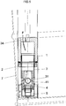
- the device further comprises a tip 1 insertable in said pipe 2.
- This nozzle 1 has at least one configuration in which it partially projects from the end of said pipe 2, in particular the main section of said pipe 2, said pipe 2 being itself able to be partially immersed by said free end in the container 7.
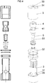
- this tip 1 is formed of two parts 3, 4 tubular. Each tubular portion 3, 4 delimits a longitudinal through passage.
- One of the parts, shown in 3 in the figures and called connecting part, is interposable between the pipe 2 and the other part called end portion 4 of the nozzle 1.
- This connecting portion 3 comprises at least one orifice 34, said outside communication with the outside of the nozzle 1, this orifice 34 for the communication of the nozzle 1 with the inside of the pipe in the inserted state of the nozzle 1 in said pipe 2.
- this external orifice 34 is an orifice disposed at the end of the connecting portion opposite the connecting end of said connecting portion at the end portion 4.
- This outer orifice 34 is formed by three openings made in the end face of said connecting portion. Indeed, this end face is partially closed to be able to include, in addition to through openings, a preferably blind hole whose role will be described below.
- This connecting portion 3 is provided with radial orifices 31 and axial orifices 35.
- the connecting portion 3 of the tip is formed of two tubular elements assembled to one another in an adjustable manner in length by screwing.
- Said elements therefore include one, a tapping and the other, a thread.
- This assembly by screwing allows to vary the length of the tip.
- One of the elements therefore comprises a partially closed end face which comprises the outer orifice 34 for communicating the tip with the pipe while the other element, through which the connecting part 3 is connected to the end portion 4 comprises the radial and axial holes.
- this element comprises, between said connecting end and the radial orifices 31, axial orifices arranged around the insertion space of the end portion 4 in said connecting portion 3.
- These axial orifices are disposed in an outer peripheral shoulder of said element and extend parallel to each other. This shoulder is sized to fit without play inside the pipe 1.
- the connecting portion 3 further comprises an annular seal 32 disposed at the screwing zone of said elements together. Again, this seal 32 is dimensioned to fit without play inside the pipe and prevent circulation between tip and pipe along the inner wall of the pipe.
- the tip 1 further comprises an end portion 4.
- This end portion 4 is in the form of a tubular body provided with radial orifices 41 regularly distributed on the circumference of said body.
- This end part 4 is equipped at its free end, that is to say at its end opposite to that connected to the connecting portion 3, a nozzle 5.
- This nozzle 5 is a rotary nozzle mounted free to rotate relative to said end portion 4 about the longitudinal axis of said tip 1. The free rotational mounting is achieved by means of a ball bearing forming a bearing of the nozzle 5 within said end portion 4 .
- This nozzle 5 is equipped with lateral orifices 51.
- the end portion 4 is slidably fitted inside the connecting portion 3 and is capable, during its displacement sliding relative to the connecting portion 3, to move from a so-called filling position of the container in which the radial orifices 41, 31 of said parts are offset axially with respect to each other and the nozzle is disposed at least partially projecting from the connecting portion 3, at a position, referred to as emptying the container, in which the radial orifices 31, 41 of said parts are positioned at least partially facing each other and said nozzle is arranged flush with the connection part 3 on the connecting end side of said connecting portion 3 at the end portion 4, and vice versa .
- the nozzle In the filling position, the nozzle, in particular the lateral orifices of the nozzle, create, with the external orifice 34 of the connecting part 3, a first product circulation path inside the nozzle, this first a flow path extending from the outer orifice to the lateral orifices of the nozzle and being borrowed by the products from the feed tank 11, when the first means 9 forced circulation of product operate.
- the radial orifices 31, 41 at least partially facing, of said parts, create with the external orifice 34 of the connecting portion, a second product circulation path inside the nozzle.
- This second circulation lane which extends from the radial orifices 31, 41 towards the external orifice 34, is taken by the contents of the container when the second forced circulation means 8 operate, the products coming from the container passing in advance to through the axial orifices 35 of the connecting portion 3 before entering the radial orifices, as illustrated by FIG. figure 5 .
- the first and second lanes are common in the portion of said lanes between the end connecting the end portion 4 to the connecting portion 3 and the outer orifice 34 of the connecting portion 4.
- each lateral orifice 51 of the nozzle delimits, from the inside towards the outside of the nozzle, a passage forming a non-zero angle with the radius of the nozzle body passing through said lateral orifice 51.
- This geometry of the jet passages formed by the lateral orifices makes it possible to drive the nozzle in rotation using said jets.
- the tip is equipped with a limit stop of the end portion 4 in the emptying position.
- This end stop is formed by an oblong longitudinal slot disposed in the end portion 4, a pin or solitary finger of the connecting portion 3 flowing inside said light. This finger bears against an end edge of said light in a position of draining the end part 4. Finger and light also form an anti-rotation stop of the end portion 4 inside the connecting portion 3.
- the connecting portion 3 of the nozzle could be axially disposed axially inside the pipe 2.
- the connecting portion 3 is equipped, at its end opposite its end of connection to the end portion 4, means 33 for connection to an actuator 6, such as a jack, insertable in the pipe 2, for a sliding mounting of the tip 1 inside the pipe 2.
- These connecting means 33 are formed by the blind hole of an end face of the connecting portion 3, mentioned above.
- the cylinder rod, axially movable, inside the main section of the pipe comes to fit forcibly into the blind hole and causes, upon actuation of the cylinder, an axial displacement back and forth of the nozzle inside the pipe, this displacement allowing an inner scraping of said pipe to ensure cleaning.
- the actuator positions the nozzle with at least a portion of the nozzle projecting from the free end of said pipe.
Landscapes
- Engineering & Computer Science (AREA)
- Mechanical Engineering (AREA)
- Supply Of Fluid Materials To The Packaging Location (AREA)
Claims (10)
- Trichter (1) der Art, die in eine Leitung (2) zur Versorgung/Ansaugung eingeführt werden kann und ausgelegt ist, um das Ende, bezeichnet als freies Ende, der Leitung (2) zu bilden, wobei die Leitung (2) selbst durch ihr freies Ende in einen Behälter (7) eingeführt werden kann, wobei der Trichter (1) aus zwei rohrförmigen Teilen (3, 4) gebildet ist, die durch eine gleitende Steckverbindung montiert sind, wobei einer der Teile (3), bezeichnet als Verbindungsteil, zwischen dem Teil (4), bezeichnet als Ende des Trichters, und der Leitung (2) angebracht werden kann, umfassend mindestens eine Öffnung (34), bezeichnet als äußere Öffnung, zur Kommunikation mit dem Äußeren des Trichters (1) und ausgelegt, um mit der Leitung (2) zu kommunizieren,
dadurch gekennzeichnet, dass die rohrförmigen Teile (3, 4) jeweils mindestens eine radiale (31, 41) Öffnung aufweisen, dadurch, dass der Endteil (4) an seinem freien Ende mit einer Düse (5) ausgestattet ist, und dadurch, dass der Endteil (4) mit Bezug auf den Verbindungsteil (3) zwischen mindestens einer Position, bezeichnet als Füllposition, des Behälters (7), in der die radialen Öffnungen (31, 41) der Teile (3, 4) axial mit Bezug aufeinander versetzt sind, und die Düse (5) mindestens teilweise vorspringend vom Verbindungsteil (3) angebracht und ausgelegt ist, um mit der äußeren Öffnung (34) einen ersten Zirkulationsweg im Inneren des Trichters (1) zu bilden, und einer Position, bezeichnet als Entleerungsposition, des Behälters (7) geleitend montiert ist, in der die radialen Öffnungen (31, 41) der Teile mindestens teilweise einander gegenüber positioniert und ausgelegt sind, um mit der mindestens einen äußeren Öffnung (34) einen zweiten Zirkulationsweg im Inneren des Trichters (1) zu bilden, und die Düse (5) bündig mit dem Verbindungsteil (3) an der Seite des Verbindungsendes des Verbindungsteils (3) an den Endteil (4) angeordnet ist. - Trichter (1) nach Anspruch 1, der Art, deren rohrförmige Teile (3, 4) beweglich in einer gleitenden Steckverbindung gemäß einer Achse, genannt Längsachse des Trichters (1), montiert sind, dadurch gekennzeichnet, dass die Düse (5) eine drehende Düse ist, die frei in Drehung mit Bezug auf den Endteil (4) um die Längsachse des Trichters (1) montiert ist.
- Trichter (1) nach Anspruch 2, dadurch gekennzeichnet, dass die Düse (5) die Form eines rohrförmigen Körpers, ausgestattet mit radialen Öffnungen (51), aufweist, wobei jede radiale Öffnung (51) der Düse (5) vom Inneren in Richtung auf das Äußere der Düse (5) einen Durchgang begrenzt, der einen Winkel von nicht gleich null mit dem Radius des Körpers der Düse bildet, die durch die radiale Öffnung (51) verläuft.
- Trichter (1) nach einem der Ansprüche 1 bis 3, dadurch gekennzeichnet, dass der Endteil (4) in gleitender teilweiser Steckverbindung im Verbindungsteil (3) montiert ist.
- Trichter (1) nach einem der Ansprüche 1 bis 4, dadurch gekennzeichnet, dass der Verbindungsteil (3) des Trichters (1) auf der Seite des Verbindungsendes mit dem Endteil (4), zwischen dem Verbindungsende und der mindestens einen radialen Öffnung (31), mit axialen Öffnungen (35) ausgestattet ist, die um den Raum zur Einführung des Endteils (4) in den Verbindungsteil (3) angeordnet sind.
- Trichter (1) nach einem der Ansprüche 1 bis 5, dadurch gekennzeichnet, dass der Verbindungsteil (3) an seinem Ende gegenüber seinem Ende zur Verbindung mit dem Endteil (4) mit Mitteln (33) zum Anschluss an eine Betätigungsvorrichtung (6) wie z.B. einer Winde, ausgestattet ist, die in die Leitung (2) eingeführt werden kann, für eine gleitende Montage des Trichters (1) im Inneren der Leitung (2).
- Trichter (1) nach einem der Ansprüche 1 bis 6, dadurch gekennzeichnet, dass der Verbindungsteil (3) des Trichters aus zwei rohrförmigen Elementen gebildet ist, die miteinander auf eine Weise zusammengebaut sind, die in der Länge durch Verschrauben einstellbar ist.
- Vorrichtung zur Versorgung/Ansaugung, insbesondere für das Füllen und/oder die Entleerung des Behälters (7), der Art, die mindestens Folgendes umfasst:- eine Leitung (2) zur Versorgung/Ansaugung wie z.B. ein Rohr, das mit mindestens einem Behälter (10, 11) verbunden werden kann,
und- einen Trichter (1), der in die Leitung (2) eingeführt werden kann und mindestens eine Konfiguration aufweist, in der er teilweise vom freien Ende der Leitung (2) hervorspringt, wobei die Leitung (2) ausgelegt ist, um teilweise durch das freie Ende in den Behälter (7) eingetaucht zu sein,
dadurch gekennzeichnet, dass der Trichter (1) einem der Ansprüche 1 bis 7 entspricht. - Vorrichtung zur Versorgung/Ansaugung nach Anspruch 8 der Art, deren Leitung (2) zur Versorgung/Ansaugung mindestens mit zwei Behältern verbunden werden kann, wobei der eine als Versorgungsbehälter (11) bezeichnet wird, der andere als Sammelbehälter (10), dadurch gekennzeichnet, dass sie erste Mittel (9) zur erzwungenen Zirkulation umfassen, die ausgelegt sind, um die Übertragung des Inhalts des Behälters (11) zur Versorgung hin zur Leitung (2) zu ermöglichen, zweite Mittel (8) zur erzwungenen Zirkulation, die ausgelegt sind, um die Übertragung des Inhalts der Leitung (2) hin zu dem Sammelbehälter (10) zu ermöglichen, wobei die ersten und zweiten Mittel zur erzwungenen Zirkulation selektiv aktiviert werden können und ausgelegt sind, um den Durchgang des Endteils (4) des Trichters von einer Position zu einer anderen je nach ihrer Aktivierung zu ermöglichen.
- Vorrichtung zur Versorgung/Ansaugung nach einem der Ansprüche 8 oder 9, dadurch gekennzeichnet, dass sie außerdem eine Betätigungsvorrichtung (6) umfasst, vorzugsweise vom Typ Winde, die auf bewegliche Weise gleitend im Inneren von mindestens einem Abschnitt der Leitung (2) positioniert werden kann, wobei diese Betätigungsvorrichtung (6) mit Mitteln zur Kopplung an den Verbindungsteil (3) des Trichters (1) ausgestattet ist, wobei diese Betätigungsvorrichtung (6) im Zustand der Kopplung an den Trichter (1) ausgelegt ist, um den Trichter (1) in gleitender Verschiebung in das Innere der Leitung (2) zu führen.
Applications Claiming Priority (2)
| Application Number | Priority Date | Filing Date | Title |
|---|---|---|---|
| FR1352417A FR3003485B1 (fr) | 2013-03-19 | 2013-03-19 | Embout du type inserable dans une conduite d’alimentation/aspiration et dispositif d'alimentation/aspiration integrant un tel embout |
| PCT/FR2014/050597 WO2014147324A1 (fr) | 2013-03-19 | 2014-03-14 | Embout du type inserable dans une conduite d'alimentation/aspiration et dispositif d'alimentation/aspiration integrant un tel embout |
Publications (2)
| Publication Number | Publication Date |
|---|---|
| EP2976166A1 EP2976166A1 (de) | 2016-01-27 |
| EP2976166B1 true EP2976166B1 (de) | 2016-12-07 |
Family
ID=48741340
Family Applications (1)
| Application Number | Title | Priority Date | Filing Date |
|---|---|---|---|
| EP14716879.3A Not-in-force EP2976166B1 (de) | 2013-03-19 | 2014-03-14 | Endstück zum einsetzen in ein zufür-/saugrohr und zufür-/saugvorrichtung mit solch einem endstück |
Country Status (3)
| Country | Link |
|---|---|
| EP (1) | EP2976166B1 (de) |
| FR (1) | FR3003485B1 (de) |
| WO (1) | WO2014147324A1 (de) |
Family Cites Families (6)
| Publication number | Priority date | Publication date | Assignee | Title |
|---|---|---|---|---|
| US2845934A (en) * | 1953-04-29 | 1958-08-05 | Portland Company | Apparatus for use in cleaning the interiors of barrels |
| WO2000021693A1 (fr) * | 1998-10-12 | 2000-04-20 | Petrojet International | Dispositif et lance agitateur hydrodynamique |
| WO2003022464A2 (en) | 2001-09-07 | 2003-03-20 | Gunclean Toftejorg Ab | Equipment and use of the equipment for cleaning a tank space or preparation of drilling mud |
| US7658198B2 (en) * | 2004-11-12 | 2010-02-09 | Distek Inc. | Washing system for dissolution vessels and the like |
| US7815748B2 (en) * | 2007-06-15 | 2010-10-19 | Gamajet Cleaning Systems, Inc. | Apparatus for cleaning stacked vessels with low head clearance |
| US7959741B2 (en) | 2008-12-18 | 2011-06-14 | Ted Joseph Green | Fuel tank cleaning method |
-
2013
- 2013-03-19 FR FR1352417A patent/FR3003485B1/fr active Active
-
2014
- 2014-03-14 WO PCT/FR2014/050597 patent/WO2014147324A1/fr not_active Ceased
- 2014-03-14 EP EP14716879.3A patent/EP2976166B1/de not_active Not-in-force
Non-Patent Citations (1)
| Title |
|---|
| None * |
Also Published As
| Publication number | Publication date |
|---|---|
| EP2976166A1 (de) | 2016-01-27 |
| WO2014147324A1 (fr) | 2014-09-25 |
| FR3003485B1 (fr) | 2015-04-17 |
| FR3003485A1 (fr) | 2014-09-26 |
Similar Documents
| Publication | Publication Date | Title |
|---|---|---|
| WO2013017803A1 (fr) | Distributeur de produit fluide. | |
| EP2960365B1 (de) | Elektrohaushaltsgerät zum bügeln, das einen behälter zur dampfdruckerzeugung umfasst, der mit einer druckauslassöffnung versehen ist | |
| EP3657978B1 (de) | Vorrichtung zur ausgabe und zum auftragen eines kosmetik- oder pflegeprodukts | |
| EP2362835B1 (de) | Schreibgerät und kappe mit innennuten für ein schreibgerät | |
| EP0375532B1 (de) | 2-Wege-Ventil zum Stromabwärts-Einbau in einer molchfähigen Flüssigkeitsverteilungsleitung | |
| EP1615525B1 (de) | Spender für einzelportionskosmetikmuster | |
| EP2976166B1 (de) | Endstück zum einsetzen in ein zufür-/saugrohr und zufür-/saugvorrichtung mit solch einem endstück | |
| FR2553306A1 (fr) | Appareil de peinture au rouleau muni d'un piston d'alimentation automatique | |
| WO2018011185A1 (fr) | Mecanisme de dosage d'une pompe a dosage proportionnel, pompe et procede de mise en œuvre associes | |
| EP3146172A1 (de) | Flüssigkeitstransfervorrichtung | |
| CA3001049C (fr) | Machine hydraulique et pompe doseuse reversible equipee d'une telle machine | |
| EP3019118B1 (de) | Vorrichtung zum einspritzen eines fluids bei tieren, insbesondere durch intranasale verabreichung | |
| WO2017187063A1 (fr) | Dispositif de distribution de produit liquide ou pateux | |
| CA2317930C (fr) | Pompe destinee a equiper un recipient | |
| EP1982774A1 (de) | Anlage und Vorrichtung zum Reinigen eines Objekts, das mit einem Flüssigkeitsumwälzkreislauf ausgestattet ist | |
| EP3177571B1 (de) | Wasserbehandlungsvorrichtung mit hoher kapazität | |
| EP2367581B1 (de) | Verstellbare druckpumpe | |
| WO2010134008A2 (fr) | Dispositif comprenant une lance munie d'un coude flexible d'angle variable utilisable dans un systeme de nettoyage | |
| FR3044991A1 (fr) | Dispositif de lavage pour surface vitree de vehicule automobile. | |
| EP2142316B1 (de) | Kammer zum waschen des ausgiessablaufs eines milchlagerungs- und -kühlbehälters | |
| EP3802402B1 (de) | Hahn mit entfernbarer kanüle | |
| FR3042482A1 (fr) | Dispositif perfectionne de transfert d'un liquide | |
| FR2593580A1 (fr) | Robinet a boisseau perfectionne | |
| EP1778554B1 (de) | Vorrichtung zum verschliessen eines fasses oder ähnlichem: | |
| FR3023270A1 (fr) | Recipient de produit fluide. |
Legal Events
| Date | Code | Title | Description |
|---|---|---|---|
| PUAI | Public reference made under article 153(3) epc to a published international application that has entered the european phase |
Free format text: ORIGINAL CODE: 0009012 |
|
| 17P | Request for examination filed |
Effective date: 20150908 |
|
| AK | Designated contracting states |
Kind code of ref document: A1 Designated state(s): AL AT BE BG CH CY CZ DE DK EE ES FI FR GB GR HR HU IE IS IT LI LT LU LV MC MK MT NL NO PL PT RO RS SE SI SK SM TR |
|
| AX | Request for extension of the european patent |
Extension state: BA ME |
|
| DAX | Request for extension of the european patent (deleted) | ||
| GRAP | Despatch of communication of intention to grant a patent |
Free format text: ORIGINAL CODE: EPIDOSNIGR1 |
|
| INTG | Intention to grant announced |
Effective date: 20160714 |
|
| GRAS | Grant fee paid |
Free format text: ORIGINAL CODE: EPIDOSNIGR3 |
|
| GRAA | (expected) grant |
Free format text: ORIGINAL CODE: 0009210 |
|
| AK | Designated contracting states |
Kind code of ref document: B1 Designated state(s): AL AT BE BG CH CY CZ DE DK EE ES FI FR GB GR HR HU IE IS IT LI LT LU LV MC MK MT NL NO PL PT RO RS SE SI SK SM TR |
|
| REG | Reference to a national code |
Ref country code: GB Ref legal event code: FG4D Free format text: NOT ENGLISH |
|
| REG | Reference to a national code |
Ref country code: CH Ref legal event code: EP Ref country code: AT Ref legal event code: REF Ref document number: 851283 Country of ref document: AT Kind code of ref document: T Effective date: 20161215 |
|
| REG | Reference to a national code |
Ref country code: IE Ref legal event code: FG4D Free format text: LANGUAGE OF EP DOCUMENT: FRENCH |
|
| REG | Reference to a national code |
Ref country code: DE Ref legal event code: R096 Ref document number: 602014005375 Country of ref document: DE |
|
| PG25 | Lapsed in a contracting state [announced via postgrant information from national office to epo] |
Ref country code: LV Free format text: LAPSE BECAUSE OF FAILURE TO SUBMIT A TRANSLATION OF THE DESCRIPTION OR TO PAY THE FEE WITHIN THE PRESCRIBED TIME-LIMIT Effective date: 20161207 |
|
| REG | Reference to a national code |
Ref country code: FR Ref legal event code: PLFP Year of fee payment: 4 |
|
| REG | Reference to a national code |
Ref country code: LT Ref legal event code: MG4D |
|
| REG | Reference to a national code |
Ref country code: NL Ref legal event code: MP Effective date: 20161207 |
|
| PG25 | Lapsed in a contracting state [announced via postgrant information from national office to epo] |
Ref country code: GR Free format text: LAPSE BECAUSE OF FAILURE TO SUBMIT A TRANSLATION OF THE DESCRIPTION OR TO PAY THE FEE WITHIN THE PRESCRIBED TIME-LIMIT Effective date: 20170308 Ref country code: LT Free format text: LAPSE BECAUSE OF FAILURE TO SUBMIT A TRANSLATION OF THE DESCRIPTION OR TO PAY THE FEE WITHIN THE PRESCRIBED TIME-LIMIT Effective date: 20161207 Ref country code: NO Free format text: LAPSE BECAUSE OF FAILURE TO SUBMIT A TRANSLATION OF THE DESCRIPTION OR TO PAY THE FEE WITHIN THE PRESCRIBED TIME-LIMIT Effective date: 20170307 Ref country code: SE Free format text: LAPSE BECAUSE OF FAILURE TO SUBMIT A TRANSLATION OF THE DESCRIPTION OR TO PAY THE FEE WITHIN THE PRESCRIBED TIME-LIMIT Effective date: 20161207 |
|
| REG | Reference to a national code |
Ref country code: AT Ref legal event code: MK05 Ref document number: 851283 Country of ref document: AT Kind code of ref document: T Effective date: 20161207 |
|
| PG25 | Lapsed in a contracting state [announced via postgrant information from national office to epo] |
Ref country code: RS Free format text: LAPSE BECAUSE OF FAILURE TO SUBMIT A TRANSLATION OF THE DESCRIPTION OR TO PAY THE FEE WITHIN THE PRESCRIBED TIME-LIMIT Effective date: 20161207 Ref country code: FI Free format text: LAPSE BECAUSE OF FAILURE TO SUBMIT A TRANSLATION OF THE DESCRIPTION OR TO PAY THE FEE WITHIN THE PRESCRIBED TIME-LIMIT Effective date: 20161207 Ref country code: HR Free format text: LAPSE BECAUSE OF FAILURE TO SUBMIT A TRANSLATION OF THE DESCRIPTION OR TO PAY THE FEE WITHIN THE PRESCRIBED TIME-LIMIT Effective date: 20161207 Ref country code: ES Free format text: LAPSE BECAUSE OF FAILURE TO SUBMIT A TRANSLATION OF THE DESCRIPTION OR TO PAY THE FEE WITHIN THE PRESCRIBED TIME-LIMIT Effective date: 20161207 |
|
| PG25 | Lapsed in a contracting state [announced via postgrant information from national office to epo] |
Ref country code: NL Free format text: LAPSE BECAUSE OF FAILURE TO SUBMIT A TRANSLATION OF THE DESCRIPTION OR TO PAY THE FEE WITHIN THE PRESCRIBED TIME-LIMIT Effective date: 20161207 |
|
| PG25 | Lapsed in a contracting state [announced via postgrant information from national office to epo] |
Ref country code: EE Free format text: LAPSE BECAUSE OF FAILURE TO SUBMIT A TRANSLATION OF THE DESCRIPTION OR TO PAY THE FEE WITHIN THE PRESCRIBED TIME-LIMIT Effective date: 20161207 Ref country code: CZ Free format text: LAPSE BECAUSE OF FAILURE TO SUBMIT A TRANSLATION OF THE DESCRIPTION OR TO PAY THE FEE WITHIN THE PRESCRIBED TIME-LIMIT Effective date: 20161207 Ref country code: SK Free format text: LAPSE BECAUSE OF FAILURE TO SUBMIT A TRANSLATION OF THE DESCRIPTION OR TO PAY THE FEE WITHIN THE PRESCRIBED TIME-LIMIT Effective date: 20161207 Ref country code: RO Free format text: LAPSE BECAUSE OF FAILURE TO SUBMIT A TRANSLATION OF THE DESCRIPTION OR TO PAY THE FEE WITHIN THE PRESCRIBED TIME-LIMIT Effective date: 20161207 Ref country code: IS Free format text: LAPSE BECAUSE OF FAILURE TO SUBMIT A TRANSLATION OF THE DESCRIPTION OR TO PAY THE FEE WITHIN THE PRESCRIBED TIME-LIMIT Effective date: 20170407 |
|
| PG25 | Lapsed in a contracting state [announced via postgrant information from national office to epo] |
Ref country code: SM Free format text: LAPSE BECAUSE OF FAILURE TO SUBMIT A TRANSLATION OF THE DESCRIPTION OR TO PAY THE FEE WITHIN THE PRESCRIBED TIME-LIMIT Effective date: 20161207 Ref country code: PL Free format text: LAPSE BECAUSE OF FAILURE TO SUBMIT A TRANSLATION OF THE DESCRIPTION OR TO PAY THE FEE WITHIN THE PRESCRIBED TIME-LIMIT Effective date: 20161207 Ref country code: PT Free format text: LAPSE BECAUSE OF FAILURE TO SUBMIT A TRANSLATION OF THE DESCRIPTION OR TO PAY THE FEE WITHIN THE PRESCRIBED TIME-LIMIT Effective date: 20170407 Ref country code: AT Free format text: LAPSE BECAUSE OF FAILURE TO SUBMIT A TRANSLATION OF THE DESCRIPTION OR TO PAY THE FEE WITHIN THE PRESCRIBED TIME-LIMIT Effective date: 20161207 Ref country code: BG Free format text: LAPSE BECAUSE OF FAILURE TO SUBMIT A TRANSLATION OF THE DESCRIPTION OR TO PAY THE FEE WITHIN THE PRESCRIBED TIME-LIMIT Effective date: 20170307 Ref country code: IT Free format text: LAPSE BECAUSE OF FAILURE TO SUBMIT A TRANSLATION OF THE DESCRIPTION OR TO PAY THE FEE WITHIN THE PRESCRIBED TIME-LIMIT Effective date: 20161207 |
|
| REG | Reference to a national code |
Ref country code: DE Ref legal event code: R097 Ref document number: 602014005375 Country of ref document: DE |
|
| PLBE | No opposition filed within time limit |
Free format text: ORIGINAL CODE: 0009261 |
|
| STAA | Information on the status of an ep patent application or granted ep patent |
Free format text: STATUS: NO OPPOSITION FILED WITHIN TIME LIMIT |
|
| 26N | No opposition filed |
Effective date: 20170908 |
|
| PG25 | Lapsed in a contracting state [announced via postgrant information from national office to epo] |
Ref country code: DK Free format text: LAPSE BECAUSE OF FAILURE TO SUBMIT A TRANSLATION OF THE DESCRIPTION OR TO PAY THE FEE WITHIN THE PRESCRIBED TIME-LIMIT Effective date: 20161207 Ref country code: SI Free format text: LAPSE BECAUSE OF FAILURE TO SUBMIT A TRANSLATION OF THE DESCRIPTION OR TO PAY THE FEE WITHIN THE PRESCRIBED TIME-LIMIT Effective date: 20161207 |
|
| REG | Reference to a national code |
Ref country code: FR Ref legal event code: PLFP Year of fee payment: 5 |
|
| PGFP | Annual fee paid to national office [announced via postgrant information from national office to epo] |
Ref country code: MC Payment date: 20180314 Year of fee payment: 5 |
|
| REG | Reference to a national code |
Ref country code: GB Ref legal event code: 732E Free format text: REGISTERED BETWEEN 20180517 AND 20180523 |
|
| REG | Reference to a national code |
Ref country code: DE Ref legal event code: R081 Ref document number: 602014005375 Country of ref document: DE Owner name: LEROUX ET LOTZ INDUSTRY, FR Free format text: FORMER OWNER: LEROUX ET LOTZ TECHNOLOGIES, NANTES, FR |
|
| REG | Reference to a national code |
Ref country code: LU Ref legal event code: PD Owner name: LEROUX LOTZ INDUSTRY; FR Free format text: FORMER OWNER: LEROUX ET LOTZ TECHNOLOGIES Effective date: 20180611 Ref country code: LU Ref legal event code: PD Owner name: LEROUX & LOTZ INDUSTRY; FR Free format text: FORMER OWNER: LEROUX ET LOTZ TECHNOLOGIES Effective date: 20180611 |
|
| REG | Reference to a national code |
Ref country code: CH Ref legal event code: PUE Owner name: LEROUX ET LOTZ INDUSTRY, FR Free format text: FORMER OWNER: LEROUX ET LOTZ TECHNOLOGIES, FR |
|
| PG25 | Lapsed in a contracting state [announced via postgrant information from national office to epo] |
Ref country code: MT Free format text: LAPSE BECAUSE OF FAILURE TO SUBMIT A TRANSLATION OF THE DESCRIPTION OR TO PAY THE FEE WITHIN THE PRESCRIBED TIME-LIMIT Effective date: 20161207 |
|
| REG | Reference to a national code |
Ref country code: BE Ref legal event code: PD Owner name: LEROUX ET LOTZ INDUSTRY; FR Free format text: DETAILS ASSIGNMENT: CHANGE OF OWNER(S), CESSION; FORMER OWNER NAME: LEROUX ET LOTZ TECHNOLOGIES Effective date: 20180717 |
|
| REG | Reference to a national code |
Ref country code: FR Ref legal event code: TP Owner name: LEROUX & LOTZ INDUSTRY, FR Effective date: 20180919 |
|
| PG25 | Lapsed in a contracting state [announced via postgrant information from national office to epo] |
Ref country code: HU Free format text: LAPSE BECAUSE OF FAILURE TO SUBMIT A TRANSLATION OF THE DESCRIPTION OR TO PAY THE FEE WITHIN THE PRESCRIBED TIME-LIMIT; INVALID AB INITIO Effective date: 20140314 |
|
| PG25 | Lapsed in a contracting state [announced via postgrant information from national office to epo] |
Ref country code: MC Free format text: LAPSE BECAUSE OF NON-PAYMENT OF DUE FEES Effective date: 20190401 Ref country code: CY Free format text: LAPSE BECAUSE OF FAILURE TO SUBMIT A TRANSLATION OF THE DESCRIPTION OR TO PAY THE FEE WITHIN THE PRESCRIBED TIME-LIMIT Effective date: 20161207 |
|
| PG25 | Lapsed in a contracting state [announced via postgrant information from national office to epo] |
Ref country code: MK Free format text: LAPSE BECAUSE OF FAILURE TO SUBMIT A TRANSLATION OF THE DESCRIPTION OR TO PAY THE FEE WITHIN THE PRESCRIBED TIME-LIMIT Effective date: 20161207 |
|
| PG25 | Lapsed in a contracting state [announced via postgrant information from national office to epo] |
Ref country code: TR Free format text: LAPSE BECAUSE OF FAILURE TO SUBMIT A TRANSLATION OF THE DESCRIPTION OR TO PAY THE FEE WITHIN THE PRESCRIBED TIME-LIMIT Effective date: 20161207 |
|
| PG25 | Lapsed in a contracting state [announced via postgrant information from national office to epo] |
Ref country code: AL Free format text: LAPSE BECAUSE OF FAILURE TO SUBMIT A TRANSLATION OF THE DESCRIPTION OR TO PAY THE FEE WITHIN THE PRESCRIBED TIME-LIMIT Effective date: 20161207 |
|
| PGFP | Annual fee paid to national office [announced via postgrant information from national office to epo] |
Ref country code: IE Payment date: 20200929 Year of fee payment: 7 Ref country code: GB Payment date: 20200929 Year of fee payment: 7 Ref country code: LU Payment date: 20200929 Year of fee payment: 7 Ref country code: DE Payment date: 20200929 Year of fee payment: 7 Ref country code: FR Payment date: 20200929 Year of fee payment: 8 |
|
| PGFP | Annual fee paid to national office [announced via postgrant information from national office to epo] |
Ref country code: BE Payment date: 20200929 Year of fee payment: 7 Ref country code: CH Payment date: 20200928 Year of fee payment: 7 |
|
| REG | Reference to a national code |
Ref country code: DE Ref legal event code: R119 Ref document number: 602014005375 Country of ref document: DE |
|
| REG | Reference to a national code |
Ref country code: CH Ref legal event code: PL |
|
| GBPC | Gb: european patent ceased through non-payment of renewal fee |
Effective date: 20210314 |
|
| REG | Reference to a national code |
Ref country code: BE Ref legal event code: MM Effective date: 20210331 |
|
| PG25 | Lapsed in a contracting state [announced via postgrant information from national office to epo] |
Ref country code: DE Free format text: LAPSE BECAUSE OF NON-PAYMENT OF DUE FEES Effective date: 20211001 Ref country code: GB Free format text: LAPSE BECAUSE OF NON-PAYMENT OF DUE FEES Effective date: 20210314 Ref country code: FR Free format text: LAPSE BECAUSE OF NON-PAYMENT OF DUE FEES Effective date: 20210331 Ref country code: IE Free format text: LAPSE BECAUSE OF NON-PAYMENT OF DUE FEES Effective date: 20210314 Ref country code: LU Free format text: LAPSE BECAUSE OF NON-PAYMENT OF DUE FEES Effective date: 20210314 Ref country code: LI Free format text: LAPSE BECAUSE OF NON-PAYMENT OF DUE FEES Effective date: 20210331 Ref country code: CH Free format text: LAPSE BECAUSE OF NON-PAYMENT OF DUE FEES Effective date: 20210331 |
|
| PG25 | Lapsed in a contracting state [announced via postgrant information from national office to epo] |
Ref country code: BE Free format text: LAPSE BECAUSE OF NON-PAYMENT OF DUE FEES Effective date: 20210331 |