EP3177571B1 - Wasserbehandlungsvorrichtung mit hoher kapazität - Google Patents
Wasserbehandlungsvorrichtung mit hoher kapazität Download PDFInfo
- Publication number
- EP3177571B1 EP3177571B1 EP15759890.5A EP15759890A EP3177571B1 EP 3177571 B1 EP3177571 B1 EP 3177571B1 EP 15759890 A EP15759890 A EP 15759890A EP 3177571 B1 EP3177571 B1 EP 3177571B1
- Authority
- EP
- European Patent Office
- Prior art keywords
- distribution
- treatment device
- tank
- outlet
- regenerating liquid
- Prior art date
- Legal status (The legal status is an assumption and is not a legal conclusion. Google has not performed a legal analysis and makes no representation as to the accuracy of the status listed.)
- Active
Links
Images

Classifications
-
- C—CHEMISTRY; METALLURGY
- C02—TREATMENT OF WATER, WASTE WATER, SEWAGE, OR SLUDGE
- C02F—TREATMENT OF WATER, WASTE WATER, SEWAGE, OR SLUDGE
- C02F1/00—Treatment of water, waste water, or sewage
- C02F1/42—Treatment of water, waste water, or sewage by ion-exchange
-
- B—PERFORMING OPERATIONS; TRANSPORTING
- B01—PHYSICAL OR CHEMICAL PROCESSES OR APPARATUS IN GENERAL
- B01J—CHEMICAL OR PHYSICAL PROCESSES, e.g. CATALYSIS OR COLLOID CHEMISTRY; THEIR RELEVANT APPARATUS
- B01J49/00—Regeneration or reactivation of ion-exchangers; Apparatus therefor
- B01J49/75—Regeneration or reactivation of ion-exchangers; Apparatus therefor of water softeners
-
- C—CHEMISTRY; METALLURGY
- C02—TREATMENT OF WATER, WASTE WATER, SEWAGE, OR SLUDGE
- C02F—TREATMENT OF WATER, WASTE WATER, SEWAGE, OR SLUDGE
- C02F1/00—Treatment of water, waste water, or sewage
- C02F1/008—Control or steering systems not provided for elsewhere in subclass C02F
-
- C—CHEMISTRY; METALLURGY
- C02—TREATMENT OF WATER, WASTE WATER, SEWAGE, OR SLUDGE
- C02F—TREATMENT OF WATER, WASTE WATER, SEWAGE, OR SLUDGE
- C02F2303/00—Specific treatment goals
- C02F2303/16—Regeneration of sorbents, filters
Definitions
- the present invention relates to a water treatment device making it possible in particular to remove from raw water the mineral substances which it contains and which are responsible for its hardness.
- a water treatment device comprises a tank containing the ion exchange resin.
- the reservoir has a neck and a tube dipping into the reservoir from the neck.
- the upper end of the tube at the neck constitutes an outlet of the reservoir, while the periphery constitutes an inlet of the reservoir.
- the water treatment device also comprises a distribution valve installed on the neck of the reservoir, the latter has a raw water inlet to be treated, and an opposite treated water outlet.
- the water treatment device comprises a regenerating liquid reservoir connected to the distribution valve and a regenerating liquid supply valve to be able to control the supply of the ion exchange resin with regenerating liquid in a phase. regeneration.
- the distribution valve has a distribution chamber and a controllable tubular member mounted in translation within this distribution chamber.
- the tubular member has two opposite asymmetric heads separated by a groove and it is connected to the regenerating liquid supply valve.
- the distribution chamber has a cylindrical portion inside which the tubular member is guided in translation, as well as a plurality of annular portions surrounding the cylindrical portion and opening radially therein.
- the plurality of annular portions two are distal and two others located between the two distal portions, are proximal.
- the distal and proximal annular portions are respectively contiguous.
- the water inlet then opens radially into one of the distal annular portions, and on the other hand, the other of the distal annular portions opens radially into the treated water outlet.
- proximal annular portions one, close to the portion distal annular in which the water inlet opens, opens radially into the reservoir inlet, while the reservoir outlet opens into the other proximal annular portion adjacent to the distal annular portion opening into the treated water outlet.
- the distribution valve comprises an actuator making it possible to control the distribution member in translation inside the cylindrical portion of the distribution chamber, and hence the regenerating liquid supply valve.
- the adjacent proximal and distal portions communicate respectively with each other, and in this way, the raw water inlet communicates with the reservoir inlet, while the outlet of tank communicates with the treated water outlet.
- the regenerating liquid supply valve is in a closed position.
- the distribution valve has two regeneration channels, one opening radially into the proximal annular portion adjacent to the distal annular portion into which the water inlet opens, the other channel opening out into the other of the proximal annular portions.
- the first allows the flow of the regenerating liquid through the inlet of the reservoir, according to a so-called co-current regeneration mode, while the second allows the flow of the regenerating liquid through the outlet of the reservoir, according to a so-called co-current mode. against a current.
- This choice of regeneration process is determined when the water treatment device is assembled according to technical criteria and / or usage. And to do this, on the one hand, the distribution member with two asymmetric heads is oriented in a given direction, while one of the regeneration channels is closed.
- the distribution member can thus be controlled in a first treatment position, thereby controlling the regenerating liquid supply valve in the open position, and in which the flow of said regenerating liquid is guided through said reservoir inlet.
- the other regeneration mode is obtained when the distribution member with two asymmetric heads is oriented in an opposite direction and the other of the regeneration channels is closed.
- the distribution member can then be controlled in a second treatment position, by controlling the even the regenerating liquid supply valve in the open position, and allowing the flow of the regenerating liquid through the outlet of the tank.
- the control of the regenerating liquid supply valve is dependent on the control of the tubular member. This requires a suitable and complex design and moreover, determines the position of the regenerating liquid supply valve on the distribution valve.
- a problem which arises and which the present invention aims to solve is to provide a water treatment device of a simplified design and therefore more advantageous.
- the present invention provides a water treatment device comprising, on the one hand, an ion exchange resin tank having a tank inlet and a tank outlet, and a distribution valve installed on said tank.
- resin having a raw water inlet and a treated water outlet and, on the other hand, a regenerating liquid tank connected to said distribution valve and a regenerating liquid supply valve controllable between an open position and a position closed
- said distribution valve comprising, on the one hand, a distribution chamber and a controllable tubular distribution member in translation mounted inside said distribution chamber and, on the other hand, an actuator for controlling said distribution member tubular between, a service position in which said raw water inlet communicates with said tank inlet, while said tank outlet communicates with said said e treated water outlet, and when said regenerating liquid supply valve is controlled in the open position, either a first treatment position in which the flow of said regenerating liquid is guided through said reservoir inlet, or a second position treatment in which the flow of said regenerating liquid is guided through said reservoir outlet.
- the water treatment device further comprises another actuator for controlling said regenerating liquid supply valve independently of said one actuator of said tubular distribution member while said distribution valve further comprises a shut-off piston mounted on it. inside said distribution chamber in the extension of said tubular distribution member, and a drive device to be able to drive said shutter piston in translation independently of said tubular distribution member, so as to be able to shut off the communication between said reservoir outlet and said treated water outlet.
- a characteristic of the invention resides in the use of another actuator making it possible to independently control the regenerating liquid supply valve, and thus to offer greater flexibility in the design of the valve. distribution valve. For, in fact, it is then easier to provide for the positioning of the tubular distribution member inside the cylindrical portion for optimum flow independently of the control of the regenerating liquid supply valve. Also, the design and production costs of the distribution valve according to the invention are lower than those of the distribution valves according to the prior art.
- Said distribution valve comprises the sealing piston mounted inside said distribution chamber to be able to close the communication between said reservoir outlet and said treated water outlet. In this way, during the regeneration phase of the ion exchange resin, the water outlet is isolated from the tank outlet, but also from any other opening.
- the distribution valve can then be controlled according to the co-current or counter-current regeneration mode without it being necessary to provide a change in position of the tubular distribution member inside the distribution chamber.
- said closure piston is mounted in the extension of said tubular distribution member.
- the drive device preferably an actuator of the type that enables the tubular distribution member to be driven, allows the shutter piston to be driven independently of the tubular distribution member.
- edit tubular distribution member has one end equipped with a seat, while said closure piston is intended to come to rest against said seat in order to close said tubular distribution member.
- the closure piston and the tubular distribution member cooperate together, so as to be able to prevent the flow of water through the tubular distribution member.
- said distribution valve comprises a chamber for receiving said regenerating liquid and two flow channels extending said receiving chamber respectively towards said reservoir inlet and towards said reservoir outlet.
- the regenerating liquid is sucked into the receiving chamber by a venturi device, for example, and then it flows through one or the other of the two flow channels, one joining the inlet of the tank, the other the outlet.
- said distribution valve advantageously comprises a shutter intended to be installed through one or the other of said two flow channels to close said one or said other of said flow channels.
- said distribution chamber has, on the one hand, a cylindrical portion, and on the other hand, two distal annular portions and two proximal annular portions, respectively surrounding said cylindrical portion and opening radially into said cylindrical portion. . Communication between some of the annular portions is established by virtue of the tubular distribution member, and its axial position in the cylindrical portion. Also, preferably, said water inlet opens radially into one of said two distal annular portions, while the other of said two distal annular portions opens radially into said treated water outlet.
- said distribution chamber has two annular blind end portions, opposite one another and respectively contiguous with said two distal annular portions.
- one of said two proximal annular portions opens radially into said reservoir inlet, while said reservoir outlet opens radially into the other of said two. proximal annular portions.
- the distal annular portion into which the water inlet opens is in communication with the proximal annular portion opening into the reservoir inlet, while the other proximal annular portion is in communication with the other distal annular portion.
- the sealing piston it is in a position spaced from said other distal annular portion to allow the treated water to flow through the treated water outlet.
- said tubular distribution member has a long head and an opposite short head, separated from each other by a groove. It will be observed that the long head extends over a length capable of being able to isolate at least one of the annular portions vis-à-vis the cylindrical portion.
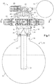
- the Figure 1 illustrates a water treatment device 10 according to the invention. It comprises a resin tank 12 having a neck 13 and containing an ion exchange resin 14, a distribution valve 16 mounted on the resin tank 12 and a regenerating liquid tank 18 connected by a conduit to the distribution valve 10.
- the distribution valve 16 comprises a valve body 20 having a cylindrical space of transverse revolution 22 passing right through it. This cylindrical space of revolution 22 defines a distribution chamber.
- the valve body 20 comprises a connecting base 23 connected to the resin reservoir 12 by its neck 13, and it is surmounted by a regenerating liquid supply valve 24 which can be controlled by a first electromechanical actuator 26.
- the valve body 20 is equipped with a tube 28 immersed in the resin tank 12. It has an upper end 30 connected to the connecting base 23 and a lower suction end 32 extending into the bottom of the tank. of resin 12.
- the upper end 30 of the tube 28 extends inside the valve body 20 by an outlet path 34 from the reservoir which opens into the cylindrical space of revolution 22.
- the valve body 20 has a path inlet 36 of the reservoir opening into the neck 13 of the reservoir around the upper end 30 of the tube 28 and on the opposite side, into the cylindrical space of revolution 22.
- the distribution valve 16 comprises, a partitioning part 38 extending longitudinally, inside the cylindrical space 22, a tubular distribution member 40 and a shutter piston 42 slidably mounted inside the cylinder. partitioning part 38, as well as two opposing actuators, a second actuator 44 to be able to actuate the tubular distribution member 40 and a third actuator 46 to be able to actuate the shutter piston 42.
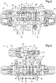
- This figure shows in more detail the second actuator 44 opposite the third actuator 46 as well as the cylindrical space of revolution transverse 22 inside which is mounted the partitioning part 38.
- the latter has equidistant radial circular ribs 48 interconnected by axial spacers 50.
- the radial circular ribs 48 each have an outer peripheral seal 52 intended to come s 'Apply in a sealed manner against the internal wall of the cylindrical space of revolution 22, and on the opposite side, an internal seal 54, against which the tubular distribution member 40 is able to come to be applied in a sealed manner.
- the partitioning part 38 has, in accordance with the variant embodiment presented on this figure 2 , eight equidistant radial circular ribs 48 defining, between them, seven successive annular portions of the distribution chamber, substantially of the same volume.
- the internal seals 54 of these radial circular ribs 48 define a circular cylindrical portion of the distribution chamber, inside which the tubular distribution member 40 will be able to be driven in translation as will be explained below. after.
- the radial circular ribs 48 define, in the distribution chamber, two proximal annular portions, a proximal inlet portion 56 and a proximal outlet portion 58 separated by a blind middle portion 60. They also define two distal annular portions , a distal inlet portion 62, contiguous with the proximal annular inlet portion 56, and a distal outlet portion 64 contiguous with the proximal outlet portion 58. Finally, the radial circular ribs 48 define two annular end portions blind, a first 66 contiguous to the distal inlet portion 62 and a second 68 contiguous to the distal annular outlet portion 64.
- tubular distribution member 40 has two asymmetrical heads, a long head 70 and a short head 72 of the same diameter, separated from each other by a groove 74.
- the long head 70 extends axially over a length substantially greater than the axial distance separating two radial circular ribs 48, while the short head 72 extends over a length substantially equal to the half-distance separating two radial circular ribs 48.
- the member of tubular distribution 40 also has an upstream opening 76 opening axially into the short head 72, and an opposed downstream opening 78 opening into the long head 70.
- the opposing downstream opening 78 defines a seat.
- the groove 74 extends axially, over a length substantially equivalent to 1.5 times the distance which separates two radial circular ribs 48.
- the heads 70, 72 come into tight contact with the internal seals 54 of the circular ribs. radial 48.
- the distal inlet portion 62 communicates axially with the proximal inlet portion 56 by virtue of the groove 74.
- the sealing piston 42 has a diameter equivalent to the diameters of the heads 70, 62, and it extends here in a retracted position.
- the distribution valve 10 comprises a raw water inlet 80, which opens radially into the distal inlet portion 62 of the distribution chamber and a treated water outlet 82 into which the distal outlet portion 64 opens radially.
- a raw water inlet 80 which opens radially into the distal inlet portion 62 of the distribution chamber
- a treated water outlet 82 into which the distal outlet portion 64 opens radially.
- the proximal inlet portion 56 opens out radially into the inlet path 36 of the reservoir, while the outlet path 34 of the reservoir opens radially into the proximal outlet portion 58.
- the cylindrical space 22 forming the distribution chamber is hermetically closed at its two opposite ends, by 2 flanges, a first flange 84 crossed in leaktight manner by a first control rod 86, and a second flange 88 through which a second control rod 90 passes.
- the first control rod 86 integrally connects the tubular distribution member 40 and the second actuator 44, while the second control rod 90 connects the shutter piston 42 and the third actuator 46.
- the valve body 20 comprises a chamber for receiving the regenerating liquid 92, on the one hand , and a first and a second flow channel 94, 96, on the other hand, extending the receiving chamber 92 and opening respectively into the proximal inlet portion 56 and into the proximal outlet portion 58.
- the channels of flow 94, 96 are intended to be closed one or the other by means of a shutter 98.
- valve body 20 comprises a suction chamber 100 opening into a venturi, not shown, which is supplied with treated water at the level of 'a supply 102.
- the regenerating liquid supply valve 24 has a closure sleeve 104 connected to the first actuator 26 by means of a control rod 106, and opposite the closure sleeve 104, a cage cylindrical reception 108 into which opens the duct of the regenerating liquid reservoir 18.
- the closure sleeve 104 is spaced outside the receiving cage 108 and the regenerating liquid can flow inside the suction chamber 100.
- the closure sleeve 104 is controlled in translation to inside the cylindrical receiving cage 108, the flow of regenerating liquid is stopped.
- the shutter piston 42 is in a retracted position releasing the distal annular outlet portion 64, while the dispensing member 40 extends into a position in which not only the distal inlet portion 62 communicates axially with the proximal inlet portion 56 via the cylindrical portion by virtue of the groove 74, but also, the proximal outlet portion 58 communicates axially with the distal outlet portion 64 by the intermediary of the cylindrical portion.
- the raw water arrives through the inlet 80, and flows radially in the distal inlet portion 62 then axially through the cylindrical portion in the proximal inlet portion to flow inside the resin reservoir 12.
- the treated water rises inside the tube 28 and flows radially in the proximal annular outlet portion 58, then then axially through the cylindrical portion in the distal outlet portion to flow towards outside through the treated water outlet 82.
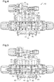
- the water treatment device 10 is in a so-called co-current regeneration phase.
- the closure sleeve 104 is spaced outside the receiving cage 108 and the regenerating liquid can flow inside the suction chamber 100.
- the closure piston 42 has been carried in a position in which it closes the distal annular outlet portion 64 vis-à-vis the cylindrical portion of the distribution chamber.
- the tubular distribution member 40 has been carried in an extreme position opposite to the shutter piston 42, in which the long head 70 seals off the proximal annular inlet portion 56 with respect to the cylindrical portion.
- the first flow channel 94 communicates directly with the inlet path 36 of the resin tank 12.
- the regenerating liquid is sucked from the suction chamber 100. to be injected through the receiving chamber 92.
- the mixture then flows through the first flow channel 94 then into the proximal annular inlet portion 56, around the long head 70 of the distribution member tubular 40 in a sealed manner vis-à-vis the contiguous annular chambers, and finally, through the inlet path 36 of the resin tank 12 to come into contact with the resin 14.
- the regenerating liquid thus makes it possible to regenerate the ion exchange resin, in co-current mode.
- the water treatment device 10 is in a so-called counter-current regeneration phase.
- the choice of the type of regeneration is defined as soon as the water treatment device 10 is fitted and depends on local uses or the characteristics of the water to be treated.
- the shutter 98 of the regenerating liquid receiving chamber 92 has been worn to close the first flow channel 94 of the regenerating liquid so as to free the second flow channel 96.
- the shutter 98 is thus installed during the mounting the dispensing valve 16.
- the distribution member 40 has been carried in an opposite extreme position, against the closure piston 42.
- the closure piston 42 is supported in the seat of the downstream opening 78 of the distribution member 40. , tightly.
- the mixture of water and regenerating liquid flows through the second flow channel 96 then into the proximal annular outlet portion 58, around the long head 70 of the tubular distribution member 40 in a sealed manner. vis-à-vis the contiguous annular chambers, and finally, through the outlet path 34 of the resin tank 12 to come into contact with the resin 14.
- the regenerating liquid thus makes it possible to regenerate the ion exchange resin, according to the so called against the tide. It will be observed that the mounting of such a water treatment device in one or other of the regeneration modes is relatively easy, since it suffices to swap the shutter 98 in the receiving chamber 92. It is not necessary There is no need to provide for the turning of the tubular distribution member 40. This is made possible by the closure piston 42.
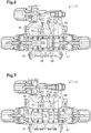
- the water treatment device 10 is in a so-called backwashing phase.
- the shutter piston 42 seals the distal annular outlet portion 64 from the cylindrical portion of the dispensing chamber, while the tubular dispensing member 40 is adjusted to a position in which the long head 70 is. straddling the middle blind potion 60 and the proximal outlet portion 58, while the short head 72 extends in a half axial part of the distal annular inlet portion 62 and in a sealed manner with respect to the blind annular portion 60.
- the raw water flows radially in the distal annular inlet portion 62 then axially, through the upstream opening 76, then inside the tubular distribution member 40 , to open radially into the distal annular outlet portion 64.
- the raw water then engages in reverse, through the outlet path 34, and thus comes back through the tube 18, the ion exchange resin towards the 'inside the tank 12.
- the figure 6 illustrates the water treatment device 10 in a rapid rinse situation.
- the shutter piston 42 seals the distal annular outlet portion 64 from the cylindrical portion of the dispensing chamber, while the tubular dispensing member 40 is adjusted to a position in which the long head 70 is. straddling the one-eyed median potion 60 and the proximal inlet portion 56.
- the raw water from the inlet 80 flows radially into the distal inlet portion 62 and then axially through the cylindrical portion in the proximal inlet portion 56 to pour into the interior of the resin reservoir 12, and also, go up at least partially in the first flow channel 94 to rinse the regenerating liquid there.
- the water also rises inside the tube 28 and flows radially in the proximal annular outlet portion 58, and then can also partially rise in the second flow channel 96 to rinse the regenerating liquid there.
- the distribution valve 16 of the water treatment device 10 as shown in the figures 1 to 7 can easily be placed in series with a succession of other identical distribution valves so as to be able to simultaneously treat large quantities of raw water.
- FIG 8 showing a water treatment device according to the invention in a second variant embodiment.
- valve body 20 ' is surmounted by a regenerating liquid feed valve 24' which can be controlled by a first electromechanical actuator 26 '.
- valve body 20 'and the regenerating liquid feed valve 24' which surmounts it are completely identical to those of the first variant embodiment.
- tubular distribution member 40 ' it is, like the tubular distribution member according to the prior art, reversible, in order to be able to regenerate the regenerating liquid in a cocurrent mode or a counter-current mode.
Landscapes
- Chemical & Material Sciences (AREA)
- Organic Chemistry (AREA)
- Life Sciences & Earth Sciences (AREA)
- Hydrology & Water Resources (AREA)
- Engineering & Computer Science (AREA)
- Environmental & Geological Engineering (AREA)
- Water Supply & Treatment (AREA)
- Chemical Kinetics & Catalysis (AREA)
- Treatment Of Water By Ion Exchange (AREA)
- Multiple-Way Valves (AREA)
Claims (8)
- Wasserbehandlungsvorrichtung (10), umfassend einerseits einen Ionenaustauscherharzbehälter (12), der einen Behältereingang und einen Behälterausgang und ein Verteilerventil (16) aufweist, das auf dem Harzbehälter (12) installiert ist und einen Rohwasserzulauf (80) und einen Ausgang des behandelten Wassers (82) aufweist, und andererseits einen Regenerierungsflüssigkeitsbehälter (18), der mit dem Verteilerventil 16) und einem Zufuhrventil für die Regenerierungsflüssigkeit (24) verbunden ist, das zwischen einer offenen Position und einer geschlossenen Position steuerbar ist, wobei das Verteilerventil (16) einerseits eine Verteilerkammer (22) und ein translatorisch steuerbares, rohrförmiges Verteilerelement (40), das in der Verteilerkammer (22) angebracht ist, und andererseits einen Aktuator (44) umfasst, um das rohrförmige Verteilerelement (40) zwischen einer Betriebsposition, in der der Rohwasserzulauf (80) mit dem Behältereingang verbunden ist, während der Behälterausgang mit dem Ausgang des behandelten Wassers (82) verbunden ist, und, wenn das Zufuhrventil für die Regenerierungsflüssigkeit (18) in offener Position gesteuert ist, entweder einer ersten Behandlungsposition, in der der Fluss der Regenerierungsflüssigkeit durch den Behältereingang geführt wird, oder einer zweiten Behandlungsposition, in der der Fluss der Regenerierungsflüssigkeit durch den Behälterausgang geführt wird, zu steuern;
dadurch gekennzeichnet, dass sie ferner einen weiteren Aktuator (26) umfasst, um das Zufuhrventil für die Regenerierungsflüssigkeit (24) unabhängig vom Aktuator (44) des rohrförmigen Verteilerelements (40) zu steuern, während das Verteilerventil (16) ferner einen Verschlusskolben (42), der in der Verteilerkammer (22) in der Verlängerung des rohrförmigen Verteilerelements (40) angebracht ist, und eine Antriebsvorrichtung (46) umfasst, um den Verschlusskolben (42) unabhängig vom rohrförmigen Verteilerelement translatorisch antreiben zu können, so dass die Verbindung zwischen dem Behälterausgang und dem Ausgang des behandelten Wassers (82) verschlossen werden kann, und dadurch, dass das rohrförmige Verteilerelement (40) ein Ende aufweist, das mit einem Sitz (78) ausgestattet ist, wobei der Verschlusskolben (42) dazu bestimmt ist, sich gegen den Sitz (78) zu legen, um das rohrförmige Verteilerelement (40) zu verschließen. - Wasserbehandlungsvorrichtung nach Anspruch 1, dadurch gekennzeichnet, dass das Verteilerventil (16) eine Aufnahmekammer (92) für die Regenerierungsflüssigkeit und zwei Durchflusskanäle (94, 96) umfasst, die die Aufnahmekammer (92) jeweils in Richtung des Behältereingangs und des Behälterausgangs verlängern.
- Wasserbehandlungsvorrichtung nach Anspruch 2, dadurch gekennzeichnet, dass das Verteilerventil (16) einen Verschluss (98) umfasst, der dazu bestimmt ist, durch einen der beiden Durchflusskanäle (94, 96) installiert zu werden, um einen der beiden Durchflusskanäle zu verschließen.
- Wasserbehandlungsvorrichtung nach einem beliebigen der Ansprüche 1 bis 3, dadurch gekennzeichnet, dass die Verteilerkammer (22) einerseits einen zylindrischen Abschnitt und andererseits zwei distale ringförmige Abschnitte (62, 64) und zwei proximale ringförmige Abschnitte (56, 58) aufweist, die jeweils den zylindrischen Abschnitt umgeben und radial in den zylindrischen Abschnitt münden.
- Wasserbehandlungsvorrichtung nach Anspruch 4, dadurch gekennzeichnet, dass der Wasserzulauf radial in den einen (62) der beiden distalen ringförmigen Abschnitte mündet, während der andere (64) der beiden distalen ringförmigen Abschnitte radial in den Ausgang des behandelten Wassers mündet.
- Wasserbehandlungsvorrichtung nach Anspruch 4 oder 5, dadurch gekennzeichnet, dass die Verteilerkammer (22) zwei ringförmige Abschnitte mit Blindenden aufweist, die jeweils zu den beiden distalen ringförmigen Abschnitten (62, 64) benachbart sind.
- Wasserbehandlungsvorrichtung nach einem beliebigen der Ansprüche 4 bis 6, dadurch gekennzeichnet, dass der eine der beiden proximalen ringförmigen Abschnitte (56) radial in den Behältereingang mündet, während der Behälterausgang radial in den anderen (58) der beiden proximalen ringförmigen Abschnitte mündet.
- Wasserbehandlungsvorrichtung nach einem beliebigen der Ansprüche 1 bis 7, dadurch gekennzeichnet, dass das Verteilerelement (40) einen langen Kopf (70) und einen gegenüberliegenden kurzen Kopf (72) aufweist, wobei die beiden Köpfe von einander durch eine Auskehlung (74) getrennt sind.
Applications Claiming Priority (2)
| Application Number | Priority Date | Filing Date | Title |
|---|---|---|---|
| FR1457595A FR3024723B1 (fr) | 2014-08-05 | 2014-08-05 | Dispositif de traitement d'eau de grande capacite |
| PCT/FR2015/052162 WO2016020621A2 (fr) | 2014-08-05 | 2015-08-05 | Dispositif de traitement d'eau de grande capacité |
Publications (2)
| Publication Number | Publication Date |
|---|---|
| EP3177571A2 EP3177571A2 (de) | 2017-06-14 |
| EP3177571B1 true EP3177571B1 (de) | 2020-10-28 |
Family
ID=51688301
Family Applications (1)
| Application Number | Title | Priority Date | Filing Date |
|---|---|---|---|
| EP15759890.5A Active EP3177571B1 (de) | 2014-08-05 | 2015-08-05 | Wasserbehandlungsvorrichtung mit hoher kapazität |
Country Status (3)
| Country | Link |
|---|---|
| EP (1) | EP3177571B1 (de) |
| FR (1) | FR3024723B1 (de) |
| WO (1) | WO2016020621A2 (de) |
Cited By (1)
| Publication number | Priority date | Publication date | Assignee | Title |
|---|---|---|---|---|
| DE102021113133A1 (de) | 2021-03-09 | 2022-09-15 | Hans Sasserath Gmbh & Co. Kg. | Verteilerarmatur für Wasserbehandlungsanordnungen |
Families Citing this family (1)
| Publication number | Priority date | Publication date | Assignee | Title |
|---|---|---|---|---|
| CN115978247A (zh) * | 2023-01-10 | 2023-04-18 | 开能健康科技集团股份有限公司 | 双罐控制阀结构 |
Family Cites Families (10)
| Publication number | Priority date | Publication date | Assignee | Title |
|---|---|---|---|---|
| CH505028A (fr) * | 1968-07-26 | 1971-03-31 | Sapir S A | Dispositif de vanne pour appareil adoucisseur d'eau |
| US3797523A (en) * | 1972-09-11 | 1974-03-19 | D Brane | Low pressure drop water softener valve assembly with dual pistons |
| EP0006409B1 (de) * | 1977-01-11 | 1982-06-23 | Fernand Lopez | Steuerungsvorrichtung zur Versorgung und Entleerung eines Gerätes, Gerät und Demineralisationsanlage ausgerüstet mit einer solchen Vorrichtung |
| US5069779A (en) * | 1989-12-15 | 1991-12-03 | Kinetico, Incorporated | Water treatment system |
| WO1997027413A1 (en) * | 1996-01-26 | 1997-07-31 | Autotrol Corporation | Adaptable control valve for fluid treatment system |
| US6001262A (en) * | 1997-06-16 | 1999-12-14 | Kelada; Maher I. | Cascade ion exchange for high purity water production |
| JP4562251B2 (ja) * | 2000-07-13 | 2010-10-13 | 株式会社丸山製作所 | 硬水軟化装置 |
| EP1385790A2 (de) * | 2000-10-25 | 2004-02-04 | Basin Water, Inc | Hocheffizientes ionenaustauschsystem zur entfernung von schadstoffen aus dem wasser |
| ITVI20010266A1 (it) * | 2001-12-21 | 2003-06-21 | A T I Applic Tecnologich E Ad | Dispositivo addolcitore per acqua |
| FR2891164B1 (fr) * | 2005-09-27 | 2007-11-30 | Steiner Michel | Adoucisseur d'eau a double mode de regeneration |
-
2014
- 2014-08-05 FR FR1457595A patent/FR3024723B1/fr active Active
-
2015
- 2015-08-05 EP EP15759890.5A patent/EP3177571B1/de active Active
- 2015-08-05 WO PCT/FR2015/052162 patent/WO2016020621A2/fr not_active Ceased
Non-Patent Citations (1)
| Title |
|---|
| None * |
Cited By (1)
| Publication number | Priority date | Publication date | Assignee | Title |
|---|---|---|---|---|
| DE102021113133A1 (de) | 2021-03-09 | 2022-09-15 | Hans Sasserath Gmbh & Co. Kg. | Verteilerarmatur für Wasserbehandlungsanordnungen |
Also Published As
| Publication number | Publication date |
|---|---|
| EP3177571A2 (de) | 2017-06-14 |
| WO2016020621A2 (fr) | 2016-02-11 |
| WO2016020621A3 (fr) | 2016-12-29 |
| FR3024723B1 (fr) | 2019-11-08 |
| FR3024723A1 (fr) | 2016-02-12 |
Similar Documents
| Publication | Publication Date | Title |
|---|---|---|
| EP2964933B1 (de) | Kompakte dosierungsvorrichtung für einen injektor mit zwei brennstoffkreisläufen für eine flugzeugturbomaschine | |
| EP0975411B1 (de) | Filter und filterkartusche mit äusserem anschlag für die filtration von flüssigkeiten, die in einem motor oder einer hydraulik zirkulieren | |
| EP0298872B1 (de) | Verfahren und Vorrichtung zur Verteilung eines primären Volumens von Flüssigkeiten in eine bestimmte Zahl von sekundären Volumen, die ein bestimmtes Verhältnis zueinander haben | |
| FR3057176A1 (fr) | Ensemble de filtrage comportant une cartouche de filtration | |
| FR2470321A1 (fr) | Vanne | |
| FR2957395A1 (fr) | Vanne thermostatique a manchon | |
| CA3019249C (fr) | Pompe a dosage proportionnel, procede de montage et de demontage d'une telle pompe | |
| FR3015061A1 (fr) | Cartouche thermostatique monocommande | |
| FR3000944A1 (fr) | Distributeur de produit fluide. | |
| EP0471610A1 (de) | Düse mit eingebautem Ventil | |
| FR3024723B1 (fr) | Dispositif de traitement d'eau de grande capacite | |
| EP3274260B1 (de) | Volumetrische dosiervorrichtung für behälterfüllmaschine | |
| WO2007036634A1 (fr) | Adoucisseur d'eau a double mode de regeneration | |
| EP3488311B1 (de) | Mischeinheit und mischarmatur mit solch einer mischeinheit | |
| FR2785356A1 (fr) | Piston de vanne et vanne equipee d'un tel piston | |
| EP3446192B1 (de) | Mischeinheit und mischarmatur mit solch einer mischeinheit | |
| EP2532405B1 (de) | Kraftstofffilter mit Wasserablasselement und Filterelement für einen solchen Filter | |
| EP3188980A1 (de) | Behälter für viskose flüssigkeit mit einem deckel mit einem hahn | |
| EP1737315A2 (de) | Materialausgabevorrichtung mit drehverschluss | |
| FR2975021A1 (fr) | Pompe de dosage et de distribution d'un produit liquide ou visqueux | |
| WO2017186676A1 (fr) | Unité de mélange et robinet mitigeur comprenant une telle unité de mélange | |
| EP3689435B1 (de) | Filter für flüssiges oder viskoses produkt, und sprühanlage, die einen solchen filter umfasst | |
| EP1230031A1 (de) | Pumpe mit schneller hin- und herbewegung | |
| FR2587780A1 (fr) | Vanne de soutirage | |
| WO2015107292A1 (fr) | Arbre a cames tubulaire formant filtre a huile centrifuge |
Legal Events
| Date | Code | Title | Description |
|---|---|---|---|
| STAA | Information on the status of an ep patent application or granted ep patent |
Free format text: STATUS: THE INTERNATIONAL PUBLICATION HAS BEEN MADE |
|
| PUAI | Public reference made under article 153(3) epc to a published international application that has entered the european phase |
Free format text: ORIGINAL CODE: 0009012 |
|
| STAA | Information on the status of an ep patent application or granted ep patent |
Free format text: STATUS: THE APPLICATION HAS BEEN PUBLISHED |
|
| AK | Designated contracting states |
Kind code of ref document: A2 Designated state(s): AL AT BE BG CH CY CZ DE DK EE ES FI FR GB GR HR HU IE IS IT LI LT LU LV MC MK MT NL NO PL PT RO RS SE SI SK SM TR |
|
| AX | Request for extension of the european patent |
Extension state: BA ME |
|
| STAA | Information on the status of an ep patent application or granted ep patent |
Free format text: STATUS: REQUEST FOR EXAMINATION WAS MADE |
|
| 17P | Request for examination filed |
Effective date: 20170629 |
|
| RBV | Designated contracting states (corrected) |
Designated state(s): AL AT BE BG CH CY CZ DE DK EE ES FI FR GB GR HR HU IE IS IT LI LT LU LV MC MK MT NL NO PL PT RO RS SE SI SK SM TR |
|
| DAV | Request for validation of the european patent (deleted) | ||
| DAX | Request for extension of the european patent (deleted) | ||
| GRAJ | Information related to disapproval of communication of intention to grant by the applicant or resumption of examination proceedings by the epo deleted |
Free format text: ORIGINAL CODE: EPIDOSDIGR1 |
|
| GRAP | Despatch of communication of intention to grant a patent |
Free format text: ORIGINAL CODE: EPIDOSNIGR1 |
|
| GRAP | Despatch of communication of intention to grant a patent |
Free format text: ORIGINAL CODE: EPIDOSNIGR1 |
|
| STAA | Information on the status of an ep patent application or granted ep patent |
Free format text: STATUS: GRANT OF PATENT IS INTENDED |
|
| INTG | Intention to grant announced |
Effective date: 20200409 |
|
| GRAJ | Information related to disapproval of communication of intention to grant by the applicant or resumption of examination proceedings by the epo deleted |
Free format text: ORIGINAL CODE: EPIDOSDIGR1 |
|
| STAA | Information on the status of an ep patent application or granted ep patent |
Free format text: STATUS: REQUEST FOR EXAMINATION WAS MADE |
|
| GRAP | Despatch of communication of intention to grant a patent |
Free format text: ORIGINAL CODE: EPIDOSNIGR1 |
|
| STAA | Information on the status of an ep patent application or granted ep patent |
Free format text: STATUS: GRANT OF PATENT IS INTENDED |
|
| INTC | Intention to grant announced (deleted) | ||
| INTG | Intention to grant announced |
Effective date: 20200529 |
|
| GRAS | Grant fee paid |
Free format text: ORIGINAL CODE: EPIDOSNIGR3 |
|
| GRAA | (expected) grant |
Free format text: ORIGINAL CODE: 0009210 |
|
| STAA | Information on the status of an ep patent application or granted ep patent |
Free format text: STATUS: THE PATENT HAS BEEN GRANTED |
|
| AK | Designated contracting states |
Kind code of ref document: B1 Designated state(s): AL AT BE BG CH CY CZ DE DK EE ES FI FR GB GR HR HU IE IS IT LI LT LU LV MC MK MT NL NO PL PT RO RS SE SI SK SM TR |
|
| RAP1 | Party data changed (applicant data changed or rights of an application transferred) |
Owner name: CAPPERS |
|
| REG | Reference to a national code |
Ref country code: GB Ref legal event code: FG4D Free format text: NOT ENGLISH |
|
| REG | Reference to a national code |
Ref country code: CH Ref legal event code: EP |
|
| REG | Reference to a national code |
Ref country code: AT Ref legal event code: REF Ref document number: 1328029 Country of ref document: AT Kind code of ref document: T Effective date: 20201115 |
|
| REG | Reference to a national code |
Ref country code: DE Ref legal event code: R096 Ref document number: 602015061158 Country of ref document: DE |
|
| REG | Reference to a national code |
Ref country code: IE Ref legal event code: FG4D Free format text: LANGUAGE OF EP DOCUMENT: FRENCH |
|
| REG | Reference to a national code |
Ref country code: AT Ref legal event code: MK05 Ref document number: 1328029 Country of ref document: AT Kind code of ref document: T Effective date: 20201028 |
|
| REG | Reference to a national code |
Ref country code: NL Ref legal event code: MP Effective date: 20201028 |
|
| PG25 | Lapsed in a contracting state [announced via postgrant information from national office to epo] |
Ref country code: NL Free format text: LAPSE BECAUSE OF FAILURE TO SUBMIT A TRANSLATION OF THE DESCRIPTION OR TO PAY THE FEE WITHIN THE PRESCRIBED TIME-LIMIT Effective date: 20201028 Ref country code: NO Free format text: LAPSE BECAUSE OF FAILURE TO SUBMIT A TRANSLATION OF THE DESCRIPTION OR TO PAY THE FEE WITHIN THE PRESCRIBED TIME-LIMIT Effective date: 20210128 Ref country code: RS Free format text: LAPSE BECAUSE OF FAILURE TO SUBMIT A TRANSLATION OF THE DESCRIPTION OR TO PAY THE FEE WITHIN THE PRESCRIBED TIME-LIMIT Effective date: 20201028 Ref country code: PT Free format text: LAPSE BECAUSE OF FAILURE TO SUBMIT A TRANSLATION OF THE DESCRIPTION OR TO PAY THE FEE WITHIN THE PRESCRIBED TIME-LIMIT Effective date: 20210301 Ref country code: FI Free format text: LAPSE BECAUSE OF FAILURE TO SUBMIT A TRANSLATION OF THE DESCRIPTION OR TO PAY THE FEE WITHIN THE PRESCRIBED TIME-LIMIT Effective date: 20201028 Ref country code: GR Free format text: LAPSE BECAUSE OF FAILURE TO SUBMIT A TRANSLATION OF THE DESCRIPTION OR TO PAY THE FEE WITHIN THE PRESCRIBED TIME-LIMIT Effective date: 20210129 |
|
| REG | Reference to a national code |
Ref country code: LT Ref legal event code: MG4D |
|
| PG25 | Lapsed in a contracting state [announced via postgrant information from national office to epo] |
Ref country code: ES Free format text: LAPSE BECAUSE OF FAILURE TO SUBMIT A TRANSLATION OF THE DESCRIPTION OR TO PAY THE FEE WITHIN THE PRESCRIBED TIME-LIMIT Effective date: 20201028 Ref country code: AT Free format text: LAPSE BECAUSE OF FAILURE TO SUBMIT A TRANSLATION OF THE DESCRIPTION OR TO PAY THE FEE WITHIN THE PRESCRIBED TIME-LIMIT Effective date: 20201028 Ref country code: BG Free format text: LAPSE BECAUSE OF FAILURE TO SUBMIT A TRANSLATION OF THE DESCRIPTION OR TO PAY THE FEE WITHIN THE PRESCRIBED TIME-LIMIT Effective date: 20210128 Ref country code: IS Free format text: LAPSE BECAUSE OF FAILURE TO SUBMIT A TRANSLATION OF THE DESCRIPTION OR TO PAY THE FEE WITHIN THE PRESCRIBED TIME-LIMIT Effective date: 20210228 Ref country code: SE Free format text: LAPSE BECAUSE OF FAILURE TO SUBMIT A TRANSLATION OF THE DESCRIPTION OR TO PAY THE FEE WITHIN THE PRESCRIBED TIME-LIMIT Effective date: 20201028 Ref country code: LV Free format text: LAPSE BECAUSE OF FAILURE TO SUBMIT A TRANSLATION OF THE DESCRIPTION OR TO PAY THE FEE WITHIN THE PRESCRIBED TIME-LIMIT Effective date: 20201028 Ref country code: PL Free format text: LAPSE BECAUSE OF FAILURE TO SUBMIT A TRANSLATION OF THE DESCRIPTION OR TO PAY THE FEE WITHIN THE PRESCRIBED TIME-LIMIT Effective date: 20201028 |
|
| PG25 | Lapsed in a contracting state [announced via postgrant information from national office to epo] |
Ref country code: HR Free format text: LAPSE BECAUSE OF FAILURE TO SUBMIT A TRANSLATION OF THE DESCRIPTION OR TO PAY THE FEE WITHIN THE PRESCRIBED TIME-LIMIT Effective date: 20201028 |
|
| REG | Reference to a national code |
Ref country code: DE Ref legal event code: R097 Ref document number: 602015061158 Country of ref document: DE |
|
| PG25 | Lapsed in a contracting state [announced via postgrant information from national office to epo] |
Ref country code: EE Free format text: LAPSE BECAUSE OF FAILURE TO SUBMIT A TRANSLATION OF THE DESCRIPTION OR TO PAY THE FEE WITHIN THE PRESCRIBED TIME-LIMIT Effective date: 20201028 Ref country code: CZ Free format text: LAPSE BECAUSE OF FAILURE TO SUBMIT A TRANSLATION OF THE DESCRIPTION OR TO PAY THE FEE WITHIN THE PRESCRIBED TIME-LIMIT Effective date: 20201028 Ref country code: SM Free format text: LAPSE BECAUSE OF FAILURE TO SUBMIT A TRANSLATION OF THE DESCRIPTION OR TO PAY THE FEE WITHIN THE PRESCRIBED TIME-LIMIT Effective date: 20201028 Ref country code: LT Free format text: LAPSE BECAUSE OF FAILURE TO SUBMIT A TRANSLATION OF THE DESCRIPTION OR TO PAY THE FEE WITHIN THE PRESCRIBED TIME-LIMIT Effective date: 20201028 Ref country code: RO Free format text: LAPSE BECAUSE OF FAILURE TO SUBMIT A TRANSLATION OF THE DESCRIPTION OR TO PAY THE FEE WITHIN THE PRESCRIBED TIME-LIMIT Effective date: 20201028 Ref country code: SK Free format text: LAPSE BECAUSE OF FAILURE TO SUBMIT A TRANSLATION OF THE DESCRIPTION OR TO PAY THE FEE WITHIN THE PRESCRIBED TIME-LIMIT Effective date: 20201028 |
|
| PG25 | Lapsed in a contracting state [announced via postgrant information from national office to epo] |
Ref country code: DK Free format text: LAPSE BECAUSE OF FAILURE TO SUBMIT A TRANSLATION OF THE DESCRIPTION OR TO PAY THE FEE WITHIN THE PRESCRIBED TIME-LIMIT Effective date: 20201028 |
|
| PLBE | No opposition filed within time limit |
Free format text: ORIGINAL CODE: 0009261 |
|
| STAA | Information on the status of an ep patent application or granted ep patent |
Free format text: STATUS: NO OPPOSITION FILED WITHIN TIME LIMIT |
|
| 26N | No opposition filed |
Effective date: 20210729 |
|
| PG25 | Lapsed in a contracting state [announced via postgrant information from national office to epo] |
Ref country code: AL Free format text: LAPSE BECAUSE OF FAILURE TO SUBMIT A TRANSLATION OF THE DESCRIPTION OR TO PAY THE FEE WITHIN THE PRESCRIBED TIME-LIMIT Effective date: 20201028 Ref country code: IT Free format text: LAPSE BECAUSE OF FAILURE TO SUBMIT A TRANSLATION OF THE DESCRIPTION OR TO PAY THE FEE WITHIN THE PRESCRIBED TIME-LIMIT Effective date: 20201028 |
|
| PG25 | Lapsed in a contracting state [announced via postgrant information from national office to epo] |
Ref country code: SI Free format text: LAPSE BECAUSE OF FAILURE TO SUBMIT A TRANSLATION OF THE DESCRIPTION OR TO PAY THE FEE WITHIN THE PRESCRIBED TIME-LIMIT Effective date: 20201028 |
|
| REG | Reference to a national code |
Ref country code: CH Ref legal event code: PL |
|
| PG25 | Lapsed in a contracting state [announced via postgrant information from national office to epo] |
Ref country code: MC Free format text: LAPSE BECAUSE OF FAILURE TO SUBMIT A TRANSLATION OF THE DESCRIPTION OR TO PAY THE FEE WITHIN THE PRESCRIBED TIME-LIMIT Effective date: 20201028 |
|
| PG25 | Lapsed in a contracting state [announced via postgrant information from national office to epo] |
Ref country code: LI Free format text: LAPSE BECAUSE OF NON-PAYMENT OF DUE FEES Effective date: 20210831 Ref country code: CH Free format text: LAPSE BECAUSE OF NON-PAYMENT OF DUE FEES Effective date: 20210831 |
|
| PG25 | Lapsed in a contracting state [announced via postgrant information from national office to epo] |
Ref country code: IS Free format text: LAPSE BECAUSE OF FAILURE TO SUBMIT A TRANSLATION OF THE DESCRIPTION OR TO PAY THE FEE WITHIN THE PRESCRIBED TIME-LIMIT Effective date: 20210228 Ref country code: LU Free format text: LAPSE BECAUSE OF NON-PAYMENT OF DUE FEES Effective date: 20210805 |
|
| PG25 | Lapsed in a contracting state [announced via postgrant information from national office to epo] |
Ref country code: IE Free format text: LAPSE BECAUSE OF NON-PAYMENT OF DUE FEES Effective date: 20210805 |
|
| PG25 | Lapsed in a contracting state [announced via postgrant information from national office to epo] |
Ref country code: HU Free format text: LAPSE BECAUSE OF FAILURE TO SUBMIT A TRANSLATION OF THE DESCRIPTION OR TO PAY THE FEE WITHIN THE PRESCRIBED TIME-LIMIT; INVALID AB INITIO Effective date: 20150805 |
|
| PG25 | Lapsed in a contracting state [announced via postgrant information from national office to epo] |
Ref country code: CY Free format text: LAPSE BECAUSE OF FAILURE TO SUBMIT A TRANSLATION OF THE DESCRIPTION OR TO PAY THE FEE WITHIN THE PRESCRIBED TIME-LIMIT Effective date: 20201028 |
|
| PG25 | Lapsed in a contracting state [announced via postgrant information from national office to epo] |
Ref country code: MK Free format text: LAPSE BECAUSE OF FAILURE TO SUBMIT A TRANSLATION OF THE DESCRIPTION OR TO PAY THE FEE WITHIN THE PRESCRIBED TIME-LIMIT Effective date: 20201028 |
|
| PG25 | Lapsed in a contracting state [announced via postgrant information from national office to epo] |
Ref country code: MT Free format text: LAPSE BECAUSE OF FAILURE TO SUBMIT A TRANSLATION OF THE DESCRIPTION OR TO PAY THE FEE WITHIN THE PRESCRIBED TIME-LIMIT Effective date: 20201028 |
|
| PGFP | Annual fee paid to national office [announced via postgrant information from national office to epo] |
Ref country code: FR Payment date: 20250526 Year of fee payment: 11 |
|
| PGFP | Annual fee paid to national office [announced via postgrant information from national office to epo] |
Ref country code: DE Payment date: 20250820 Year of fee payment: 11 |
|
| PGFP | Annual fee paid to national office [announced via postgrant information from national office to epo] |
Ref country code: GB Payment date: 20250820 Year of fee payment: 11 Ref country code: BE Payment date: 20250820 Year of fee payment: 11 |
|
| PG25 | Lapsed in a contracting state [announced via postgrant information from national office to epo] |
Ref country code: TR Free format text: LAPSE BECAUSE OF FAILURE TO SUBMIT A TRANSLATION OF THE DESCRIPTION OR TO PAY THE FEE WITHIN THE PRESCRIBED TIME-LIMIT Effective date: 20201028 |