EP2977127A1 - Gussvorrichtung - Google Patents
Gussvorrichtung Download PDFInfo
- Publication number
- EP2977127A1 EP2977127A1 EP13878814.6A EP13878814A EP2977127A1 EP 2977127 A1 EP2977127 A1 EP 2977127A1 EP 13878814 A EP13878814 A EP 13878814A EP 2977127 A1 EP2977127 A1 EP 2977127A1
- Authority
- EP
- European Patent Office
- Prior art keywords
- cavity
- molten metal
- pressurizing
- pressurizing chamber
- opening
- Prior art date
- Legal status (The legal status is an assumption and is not a legal conclusion. Google has not performed a legal analysis and makes no representation as to the accuracy of the status listed.)
- Withdrawn
Links
- 238000005266 casting Methods 0.000 title claims abstract description 17
- 229910052751 metal Inorganic materials 0.000 claims abstract description 63
- 239000002184 metal Substances 0.000 claims abstract description 63
- 239000007789 gas Substances 0.000 description 14
- 238000007872 degassing Methods 0.000 description 10
- 230000007246 mechanism Effects 0.000 description 5
- 238000010586 diagram Methods 0.000 description 3
- 239000011261 inert gas Substances 0.000 description 3
- 238000007789 sealing Methods 0.000 description 3
- 229910052782 aluminium Inorganic materials 0.000 description 2
- XAGFODPZIPBFFR-UHFFFAOYSA-N aluminium Chemical compound [Al] XAGFODPZIPBFFR-UHFFFAOYSA-N 0.000 description 2
- 238000004891 communication Methods 0.000 description 2
- 230000000052 comparative effect Effects 0.000 description 2
- 230000003247 decreasing effect Effects 0.000 description 2
- 238000004512 die casting Methods 0.000 description 2
- 238000007792 addition Methods 0.000 description 1
- 239000002131 composite material Substances 0.000 description 1
- 238000001816 cooling Methods 0.000 description 1
- 238000007599 discharging Methods 0.000 description 1
- 230000000694 effects Effects 0.000 description 1
- 238000005429 filling process Methods 0.000 description 1
- 239000000463 material Substances 0.000 description 1
- 238000000034 method Methods 0.000 description 1
- 238000012986 modification Methods 0.000 description 1
- 230000004048 modification Effects 0.000 description 1
- 230000035515 penetration Effects 0.000 description 1
- 239000003566 sealing material Substances 0.000 description 1
- 238000007711 solidification Methods 0.000 description 1
- 230000008023 solidification Effects 0.000 description 1
Images


Classifications
-
- B—PERFORMING OPERATIONS; TRANSPORTING
- B22—CASTING; POWDER METALLURGY
- B22D—CASTING OF METALS; CASTING OF OTHER SUBSTANCES BY THE SAME PROCESSES OR DEVICES
- B22D18/00—Pressure casting; Vacuum casting
- B22D18/04—Low pressure casting, i.e. making use of pressures up to a few bars to fill the mould
-
- B—PERFORMING OPERATIONS; TRANSPORTING
- B22—CASTING; POWDER METALLURGY
- B22C—FOUNDRY MOULDING
- B22C9/00—Moulds or cores; Moulding processes
- B22C9/06—Permanent moulds for shaped castings
- B22C9/067—Venting means for moulds
-
- B—PERFORMING OPERATIONS; TRANSPORTING
- B22—CASTING; POWDER METALLURGY
- B22D—CASTING OF METALS; CASTING OF OTHER SUBSTANCES BY THE SAME PROCESSES OR DEVICES
- B22D18/00—Pressure casting; Vacuum casting
- B22D18/02—Pressure casting making use of mechanical pressure devices, e.g. cast-forging
-
- B—PERFORMING OPERATIONS; TRANSPORTING
- B22—CASTING; POWDER METALLURGY
- B22D—CASTING OF METALS; CASTING OF OTHER SUBSTANCES BY THE SAME PROCESSES OR DEVICES
- B22D18/00—Pressure casting; Vacuum casting
- B22D18/06—Vacuum casting, i.e. making use of vacuum to fill the mould
-
- B—PERFORMING OPERATIONS; TRANSPORTING
- B22—CASTING; POWDER METALLURGY
- B22D—CASTING OF METALS; CASTING OF OTHER SUBSTANCES BY THE SAME PROCESSES OR DEVICES
- B22D18/00—Pressure casting; Vacuum casting
- B22D18/08—Controlling, supervising, e.g. for safety reasons
-
- B—PERFORMING OPERATIONS; TRANSPORTING
- B22—CASTING; POWDER METALLURGY
- B22D—CASTING OF METALS; CASTING OF OTHER SUBSTANCES BY THE SAME PROCESSES OR DEVICES
- B22D17/00—Pressure die casting or injection die casting, i.e. casting in which the metal is forced into a mould under high pressure
- B22D17/14—Machines with evacuated die cavity
- B22D17/145—Venting means therefor
Definitions
- the present invention relates to a casting device.
- Patent Literature 1 a gate piston pin is opened after making a molten metal side to positive pressure and a cavity side to negative pressure. Therefore, the molten metal may be splashed at the moment of opening the gate piston pin due to the pressure difference, thereby causing a flow mark and cold shut in a molded object. In other words, there may be a problem in which quality of the molded object is deteriorated.
- Patent Literature 1 JP 5-146864 A
- the present invention is made considering the above-described situation, and directed to providing a casting device capable of improving quality of a casting product by preventing molten metal from being splashed.
- the casting device includes a die, a pressurizing chamber, a stalk, a pressurizing means, a depressurizing means, and a control device.
- the die is formed with a cavity including an opening at a lower portion thereof.
- the pressurizing chamber is disposed below the die, and contains molten metal, and further is formed with a sealed space above the molten metal.
- the stalk formed in a cylindrical shape has an upper end opening communicating with the opening of the cavity, and a lower end opening immersed into the molten metal contained inside the pressurizing chamber.
- the pressurizing means pressurizes the inside of the pressurizing chamber by supplying a gas to the sealed space of the pressurizing chamber.
- the depressurizing means depressurizes the inside of the cavity by discharging the gas from the cavity.
- the control device when the molten metal is provided to the cavity from the pressurizing chamber, pressurizes the inside of the pressurizing chamber by the pressurizing means until the molten metal reaches the opening of the cavity and depressurizes the inside of the cavity by the depressurizing means while continuing pressurizing the inside of the pressurizing chamber after the molten metal reaches the opening of the cavity.
- the inside of the pressurizing chamber is pressurized by the pressurizing means until the molten metal reaches the opening of the cavity, and after the molten metal reaches the opening of the cavity, the inside of the cavity is depressurized by the depressurizing means while continuing pressurizing the inside of the pressurizing chamber.
- Fig. 1 is a schematic view illustrating the casting device according to an embodiment.
- the casting device includes a pressurizing chamber (crucible) 10 to pressurize molten metal A as illustrated in Fig. 1 .
- a container 11 to keep the molten metal A is provided inside the pressurizing chamber 10.
- An upper end opening of the pressurizing chamber 10 is closed with a stationary platen 12, and a sealed space is formed inside the pressurizing chamber 10.
- the sealed space (pressurizing chamber 10) is in communication with a gas supply passage 13 and a gas discharge passage 14.
- the gas supply passage 13 is connected to the pressurizing source 16 via a valve 15, and supplies an inert gas into the pressurizing chamber 10.
- the gas discharge passage 14 opens the pressurizing chamber 10 to atmosphere via a valve 17.
- An upper end of a cylindrical stalk 18 is fixed at a center of the stationary platen 12, and both ends of the stalk 18 are opened. A lower end of the stalk 18 is immersed into the molten metal A contained inside the pressurizing chamber 10.
- a fixed die 19 is mounted on an upper surface of the stationary platen 12.
- a movable die 21 is mounted on a lower surface of a moving platen 20 configured movable upward relative to the fixed die 19.
- a cavity 22 is formed.
- an opening 23a is formed at a gate portion communicating with the cavity 22, and the opening 23a is in communication with an upper end portion of the stalk 18.
- a degassing passage 23b to degas a gas from the cavity 22 is connected to the fixed die 19, and chill vents 23c to avoid penetration of the molten metal A into the degassing passage 23b are disposed between the cavity 22 and the degassing passage 23b.
- a gate seal pin 24, a center pressurizing pin 25, and a plurality of partial pressurizing pins 26 are mounted on the movable die 21.
- the gate seal pin 24 is formed movable back and forth relative to the opening 23a to open and close the opening 23a.
- the gate seal pin 24 is formed in a substantially bar-like shape.
- the center pressurizing pin 25 is formed movable back and forth relative to a molten metal basin 27 communicating with the cavity 22 and pressurizes the inside of the cavity 22.
- the center pressurizing pin 25 is formed in a cylindrical shape surrounding the gate seal pin 24.
- the partial pressurizing pin 26 is formed movable back and forth relative to a molten metal basin 28 communicating with the cavity 22, and pressurizes the inside of the cavity 22.
- the partial pressurizing pin 26 is formed in a substantially bar-like shape.
- the gate seal pin 24 and the center pressurizing pin 25 respectively have upper end portions connected to a piston mechanism 29 as a driving means, and each one is movable in a vertical direction.
- the partial pressurizing pin 26 has an upper end portion connected to a piston mechanism 30 as a driving means, and is movable in a vertical direction.
- the casting device includes a vacuum device 32 connected to the degassing passage 23b via a degassing valve 31, and a controller 33.
- the vacuum device 32 discharges the gas from the cavity 22 via the degassing valve 31 and the degassing passage 23b, and depressurizes the inside of the cavity 22.
- the vacuum device 32 includes a vacuum tank 321, a vacuum pump 322 to perform vacuum drawing in the vacuum tank 321, and a motor 323 to drive the vacuum pump 322.
- the controller 33 controls the valve 15 and the pressurizing source 16 to pressurize the inside of the pressurizing chamber 10.
- the controller 33 controls the valve 17 to open the pressurizing chamber 10 to the atmosphere.
- the controller 33 controls the valve 31 and the vacuum device 32 to discharge the gas contained inside the cavity 22, and depressurizes the inside of the cavity 22.
- the controller 33 controls the piston mechanism 29 to open and close the opening 23a by the gate seal pin 24.
- the controller 33 controls the piston mechanisms 29, 30 to pressurize the inside of the cavity 22 by the center pressurizing pin 25 and the partial pressurizing pin 26.
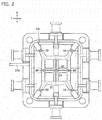
- FIG. 2 is a plan view illustrating the cavity 22. As illustrated in Fig. 2 , the cavity 22 extends symmetrically in an X direction and a Y direction centering the gate seal pin 24 and the center pressurizing pin 25. In an example illustrated in Fig. 2 , six partial pressurizing pins 26 are provided in the vicinity of end portions of the cavity 22.
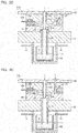
- Figs. 3A to 3D are schematic views illustrating the filling operation.
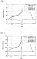
- Fig. 4 is a diagram illustrating changes of pressure P1 applied to the cavity 22 from the pressurizing source 16, pressure P2 to vacuum the cavity 22 from the vacuum device 32, and differential pressure P3 between the pressure P1 and P2 (hereinafter referred to as filling differential pressure) with passage of time.
- the filling operation is executed based on the passage of time in the present embodiment. For example, the time when a molten metal level of the molten metal A reaches the opening 23a is preliminarily measured, and filling operation is executed based on this measured time.
- the controller 33 first opens the valve 15 at time t11 as illustrated in Fig. 3A . Then, the controller 33 supplies an inert gas to the sealed space of the pressurizing chamber 10 from the pressurizing source 16 via the gas supply passage 13. By this, the pressure P1 applied to the pressurizing chamber 10 from the pressurizing source 16 is increased from time t11 and forth as illustrated in Fig. 4 . Therefore, the filling differential pressure P3 is increased as illustrated in Fig. 4 , thereby raising the molten metal level of the molten metal A.
- the controller 33 continuously supplies the inert gas to the sealed space of the pressurizing chamber 10 from the pressurizing source 16 via the gas supply passage 13 even after the molten metal A reaches the opening 23a of the cavity 22 at time t12. Further, as illustrated in Fig. 3B , the controller 33 makes the cavity 22 communicate with the vacuum tank 321 by opening the valve 31. By this, the gas contained inside the cavity 22 is discharged to the vacuum tank 321 via the degassing passage 23b.
- a sensor may be used to detect the molten metal A reaching the opening 23a of the cavity 22, or the time when the molten metal level reaches the opening 23a under a predetermined pressure is preliminarily measured and control may be executed based on this measured time.
- the pressure P1 applied to the cavity 22 from the pressurizing source 16 is continuously increased by the control illustrated in Fig. 3B even after time 112.
- an increasing speed of the pressure P1 is not constant depending on the shape of the cavity 22.
- a depressurizing (vacuum) degree inside the die is increased by discharge from the cavity 22 executed by the vacuum device 32.
- the pressure P2 applied to the cavity 22 is decreased in a minus direction as illustrated in Fig. 4 .
- the filling differential pressure P3 is increased by the pressure P1, P2 as illustrated in Fig. 4 .
- the controller 33 opens the valve 17 to open the pressurizing chamber 10 to the atmosphere, thereby lowing the molten metal level of the molten metal A inside the stalk 18.
- the controller 33 may push down the center pressurizing pin 25 as illustrated in Fig. 3D and pressurize the inside of the cavity 22 so as to further increase the pressure.
- pressurization by the partial pressurizing pin 26 may be combined as well.
- the gate seal pin 24 and the center pressurizing pin 25 may be integrally formed, and in this case, gate closing and pressurizing are continuously operated by lowing a single cylinder. After solidification of the molten metal A inside the cavity 22, a product is taken out by moving up the movable die 21.
- the molten metal A may rush into the cavity 22 like a jet flow, thereby causing a flow mark and cold shut in a molded object.
- the inside of the pressurizing chamber 10 is pressurized until the molten metal A reaches the opening 23a of the cavity 22 in a state that the gate seal pin 24 is opened as described above, and pressurizing the inside of the pressurizing chamber 10 is continued after the molten metal A reaches the opening 23a of the cavity 22, while the inside of the cavity 22 is gradually depressurized as illustrated in Fig. 4 .
- This can gradually increase the filling differential pressure P3 when the molten metal flows into the die. Therefore, according to the present embodiment, the molten metal A is prevented from being splashed and the molded object can be prevented from causing the flow mark and cold shut.
- the pressure inside the cavity 22 is controlled by the vacuum device 32 and the pressurizing chamber 10. Therefore, the present embodiment can provide a simple structure, compared to the case of controlling the pressure inside the cavity 22 by providing a plurality of pressurizing chambers. Further, compared to the case of controlling the pressure inside the cavity 22 only by the pressurizing chamber 10, a load applied to the pressurizing chamber 10 can be reduced and airtightness of the pressurizing chamber 10 can be secured in the present embodiment.
- Fig. 5 illustrates changes of the pressure P1 applied to the cavity 22 from the pressurizing source 16, pressure P2 of the cavity 22, and the differential pressure P3 between the pressure P1 and P2 with passage of time in a comparative example in which the vacuum device 32 is not combined.
- a flow property of the molten metal A inside the cavity 22 can be improved because the back pressure inside the cavity 22 can be reduced by the vacuum device 32.
Landscapes
- Engineering & Computer Science (AREA)
- Mechanical Engineering (AREA)
- Molds, Cores, And Manufacturing Methods Thereof (AREA)
- Moulds For Moulding Plastics Or The Like (AREA)
Applications Claiming Priority (2)
| Application Number | Priority Date | Filing Date | Title |
|---|---|---|---|
| JP2013057572A JP5527451B1 (ja) | 2013-03-21 | 2013-03-21 | 鋳造装置 |
| PCT/JP2013/082182 WO2014147892A1 (ja) | 2013-03-21 | 2013-11-29 | 鋳造装置 |
Publications (2)
| Publication Number | Publication Date |
|---|---|
| EP2977127A1 true EP2977127A1 (de) | 2016-01-27 |
| EP2977127A4 EP2977127A4 (de) | 2016-04-06 |
Family
ID=51175757
Family Applications (1)
| Application Number | Title | Priority Date | Filing Date |
|---|---|---|---|
| EP13878814.6A Withdrawn EP2977127A4 (de) | 2013-03-21 | 2013-11-29 | Gussvorrichtung |
Country Status (6)
| Country | Link |
|---|---|
| US (1) | US20160045955A1 (de) |
| EP (1) | EP2977127A4 (de) |
| JP (1) | JP5527451B1 (de) |
| KR (1) | KR20150131384A (de) |
| CN (1) | CN105073302B (de) |
| WO (1) | WO2014147892A1 (de) |
Cited By (3)
| Publication number | Priority date | Publication date | Assignee | Title |
|---|---|---|---|---|
| IT201900018053A1 (it) * | 2019-10-07 | 2021-04-07 | Euromac Srl | Apparecchiatura e procedimento per la fusione e stampaggio allo stato semi-solido di oggetti in ottone, bronzo, leghe di alluminio, magnesio e leghe leggere e simili. |
| EP3127633B1 (de) * | 2014-03-31 | 2022-05-11 | Nissan Motor Co., Ltd. | Giessverfahren und giessvorrichtung |
| WO2022112611A1 (de) * | 2020-11-30 | 2022-06-02 | Kurtz Gmbh & Co. Kg | KOKILLE, VORRICHTUNG UND VERFAHREN ZUM NIEDERDRUCKGIEßEN |
Families Citing this family (17)
| Publication number | Priority date | Publication date | Assignee | Title |
|---|---|---|---|---|
| CN107107181B (zh) | 2014-12-24 | 2020-05-22 | 日产自动车株式会社 | 低压铸造装置和低压铸造方法 |
| JP6406509B2 (ja) * | 2014-12-26 | 2018-10-17 | 日産自動車株式会社 | 鋳造装置及び鋳造方法 |
| JP6406510B2 (ja) * | 2014-12-26 | 2018-10-17 | 日産自動車株式会社 | 鋳造方法及び鋳造装置 |
| US10286449B2 (en) * | 2015-02-24 | 2019-05-14 | Nissan Motor Co., Ltd. | Casting device and casting method |
| JP6460326B2 (ja) * | 2015-02-25 | 2019-01-30 | 日産自動車株式会社 | 鋳造装置及び鋳造方法 |
| JP6489500B2 (ja) * | 2015-02-26 | 2019-03-27 | 日産自動車株式会社 | 鋳造装置及び鋳造方法 |
| CN105499513A (zh) * | 2015-12-23 | 2016-04-20 | 哈尔滨工业大学 | 液态充填局部加压补缩铝合金汽车轮毂制造装置及其方法 |
| CN107639221A (zh) * | 2017-08-22 | 2018-01-30 | 北京北方恒利科技发展有限公司 | 一种双金属缸体的铸造方法 |
| CN107321959B (zh) * | 2017-09-05 | 2019-04-16 | 哈尔滨工业大学 | 大型船舶用铜合金螺旋桨差压铸造升液截止机构 |
| CN108580843A (zh) * | 2018-03-13 | 2018-09-28 | 中信戴卡股份有限公司 | 一种铝车轮连铸连锻成形工艺 |
| CN108311668A (zh) * | 2018-03-13 | 2018-07-24 | 中信戴卡股份有限公司 | 一种铝合金低压铸造装置及工艺 |
| CN109047721B (zh) * | 2018-10-18 | 2020-06-05 | 四川省犍为恒益铝业有限公司 | 一种车用箱体低压铸造模具 |
| DE102020100701A1 (de) * | 2020-01-14 | 2021-07-15 | Audi Aktiengesellschaft | Verfahren zum Herstellen einer Kraftwagenfelge aus Aluminium oder einer Aluminiumlegierung für ein Rad eines Kraftfahrzeugs sowie entsprechende Kraftwagenfelge |
| KR102409575B1 (ko) * | 2021-12-20 | 2022-06-22 | (주)서영 | 주조 품질 향상을 위한 진공 모듈 장치 |
| IT202200026292A1 (it) * | 2022-12-21 | 2024-06-21 | Euromac Srl | Apparecchiatura e procedimento per la fusione e lo stampaggio allo stato semi-solido di oggetti in metallo |
| KR102872415B1 (ko) * | 2023-01-31 | 2025-10-23 | 디엔케이모빌리티 주식회사 | 고진공 다단가압 저압주조장치 및 그 방법 |
| WO2025262651A1 (en) * | 2024-06-21 | 2025-12-26 | Colosio S.R.L. | Apparatus and method for forging |
Family Cites Families (13)
| Publication number | Priority date | Publication date | Assignee | Title |
|---|---|---|---|---|
| FR2583321B1 (fr) * | 1985-06-18 | 1987-09-18 | Etude Dev Metallurg | Procede de coulee sous basse pression isostatique et machine pour sa mise en oeuvre |
| WO1993007977A1 (fr) * | 1991-10-25 | 1993-04-29 | Toyota Jidosha Kabushiki Kaisha | Procede et dispositif de coulee sous vide |
| JPH05146864A (ja) | 1991-11-27 | 1993-06-15 | Toyota Motor Corp | 鋳造装置 |
| JPH06264157A (ja) * | 1993-03-09 | 1994-09-20 | Hitachi Metals Ltd | アルミニウム合金の鋳造方法及びアルミニウム合金部品 |
| JP3097400B2 (ja) * | 1993-07-20 | 2000-10-10 | トヨタ自動車株式会社 | 真空鋳造法とその装置 |
| JP3147285B2 (ja) * | 1995-07-07 | 2001-03-19 | 新東工業株式会社 | 低圧鋳造設備 |
| DE19943153C1 (de) * | 1998-03-19 | 2001-01-25 | Gut Gieserei Umwelt Technik Gm | Gießvorrichtung mit Nachverdichtung |
| US6742568B2 (en) * | 2001-05-29 | 2004-06-01 | Alcoa Inc. | Casting apparatus including a gas driven molten metal injector and method |
| ITPD20020167A1 (it) * | 2002-06-21 | 2003-12-22 | Bbs Riva Spa | Attrezzatura per realizzare oggetti in alluminio, leghe di alluminio,leghe leggere e simili, e procedimento attuato da detta attrezzatura |
| CA2567290A1 (en) * | 2004-05-18 | 2005-11-24 | Kosei Aluminum Co., Ltd | Vertical casting apparatus and vertical casting method |
| JP2007253168A (ja) * | 2006-03-20 | 2007-10-04 | Kosei Aluminum Co Ltd | 竪型鋳造装置及び竪型鋳造方法 |
| ITTO20070934A1 (it) * | 2007-12-21 | 2009-06-22 | Solmar S A S Di Luisa Maria Ma | Apparecchiatura per la fabbricazione di articoli di metallo, in particolare di lega leggera. |
| JP4897734B2 (ja) * | 2008-04-17 | 2012-03-14 | 谷田合金株式会社 | 差圧鋳造装置 |
-
2013
- 2013-03-21 JP JP2013057572A patent/JP5527451B1/ja not_active Expired - Fee Related
- 2013-11-29 US US14/779,002 patent/US20160045955A1/en not_active Abandoned
- 2013-11-29 CN CN201380074842.5A patent/CN105073302B/zh active Active
- 2013-11-29 KR KR1020157030092A patent/KR20150131384A/ko not_active Ceased
- 2013-11-29 EP EP13878814.6A patent/EP2977127A4/de not_active Withdrawn
- 2013-11-29 WO PCT/JP2013/082182 patent/WO2014147892A1/ja not_active Ceased
Cited By (6)
| Publication number | Priority date | Publication date | Assignee | Title |
|---|---|---|---|---|
| EP3127633B1 (de) * | 2014-03-31 | 2022-05-11 | Nissan Motor Co., Ltd. | Giessverfahren und giessvorrichtung |
| IT201900018053A1 (it) * | 2019-10-07 | 2021-04-07 | Euromac Srl | Apparecchiatura e procedimento per la fusione e stampaggio allo stato semi-solido di oggetti in ottone, bronzo, leghe di alluminio, magnesio e leghe leggere e simili. |
| WO2021070044A1 (en) * | 2019-10-07 | 2021-04-15 | Euromac Srl | Apparatus and method for the die casting in the semisolid state of objects made of brass, bronze, alloys of aluminum, magnesium and light alloys and the like |
| CN114502300A (zh) * | 2019-10-07 | 2022-05-13 | 优洛麦克责任有限公司 | 用于在由黄铜、青铜、铝合金、镁合金和轻合金等制成的物体的半固体状态下进行压铸的设备和方法 |
| US11752546B2 (en) | 2019-10-07 | 2023-09-12 | Euromac Srl | Apparatus and method for the die casting in the semisolid state of objects made of brass, bronze, alloys of aluminum, magnesium and light alloys and the like |
| WO2022112611A1 (de) * | 2020-11-30 | 2022-06-02 | Kurtz Gmbh & Co. Kg | KOKILLE, VORRICHTUNG UND VERFAHREN ZUM NIEDERDRUCKGIEßEN |
Also Published As
| Publication number | Publication date |
|---|---|
| JP5527451B1 (ja) | 2014-06-18 |
| WO2014147892A1 (ja) | 2014-09-25 |
| EP2977127A4 (de) | 2016-04-06 |
| CN105073302B (zh) | 2017-08-08 |
| KR20150131384A (ko) | 2015-11-24 |
| CN105073302A (zh) | 2015-11-18 |
| JP2014180696A (ja) | 2014-09-29 |
| US20160045955A1 (en) | 2016-02-18 |
Similar Documents
| Publication | Publication Date | Title |
|---|---|---|
| EP2977127A1 (de) | Gussvorrichtung | |
| EP3263247B1 (de) | Giessvorrichtung und giessverfahren | |
| EP3127633B1 (de) | Giessverfahren und giessvorrichtung | |
| US20070215308A1 (en) | Vertical Casting Apparatus and Vertical Casting Method | |
| JP6379847B2 (ja) | 鋳造装置 | |
| CN106041020A (zh) | 用于压铸模具通气的一元化结构阀门组装体 | |
| US11752546B2 (en) | Apparatus and method for the die casting in the semisolid state of objects made of brass, bronze, alloys of aluminum, magnesium and light alloys and the like | |
| JP2007253168A (ja) | 竪型鋳造装置及び竪型鋳造方法 | |
| JP6183272B2 (ja) | 鋳造装置及び鋳造方法 | |
| JP3097400B2 (ja) | 真空鋳造法とその装置 | |
| JP2008044008A (ja) | 低圧鋳造装置および不活性ガスの充満方法 | |
| JP6489500B2 (ja) | 鋳造装置及び鋳造方法 | |
| CN109351935A (zh) | 一种压铸机定量进料装置 | |
| CN209393961U (zh) | 一种压铸机定量进料装置 | |
| CN216155452U (zh) | 用于用填充产品填充容器的设备 | |
| CN106457374A (zh) | 铸造装置和压铸方法 | |
| JPH05146865A (ja) | 鋳造装置 | |
| CN110756762A (zh) | 一种压铸模具真空阀及真空压铸模具 | |
| KR20250126757A (ko) | 반고체 상태의 금속 대상물을 다이캐스팅하기 위한 장치 및 방법 | |
| JP6285754B2 (ja) | 空気充填装置 | |
| KR20210031180A (ko) | 다단진공 다이캐스팅용 진공게이트밸브 | |
| JP2016155152A (ja) | 鋳造装置及び鋳造方法 | |
| JPH06297130A (ja) | 鋳造装置 |
Legal Events
| Date | Code | Title | Description |
|---|---|---|---|
| PUAI | Public reference made under article 153(3) epc to a published international application that has entered the european phase |
Free format text: ORIGINAL CODE: 0009012 |
|
| 17P | Request for examination filed |
Effective date: 20150907 |
|
| AK | Designated contracting states |
Kind code of ref document: A1 Designated state(s): AL AT BE BG CH CY CZ DE DK EE ES FI FR GB GR HR HU IE IS IT LI LT LU LV MC MK MT NL NO PL PT RO RS SE SI SK SM TR |
|
| AX | Request for extension of the european patent |
Extension state: BA ME |
|
| A4 | Supplementary search report drawn up and despatched |
Effective date: 20160308 |
|
| RIC1 | Information provided on ipc code assigned before grant |
Ipc: B22D 18/08 20060101ALI20160302BHEP Ipc: B22D 18/06 20060101ALI20160302BHEP Ipc: B22D 18/04 20060101AFI20160302BHEP |
|
| DAX | Request for extension of the european patent (deleted) | ||
| STAA | Information on the status of an ep patent application or granted ep patent |
Free format text: STATUS: EXAMINATION IS IN PROGRESS |
|
| 17Q | First examination report despatched |
Effective date: 20161109 |
|
| GRAP | Despatch of communication of intention to grant a patent |
Free format text: ORIGINAL CODE: EPIDOSNIGR1 |
|
| STAA | Information on the status of an ep patent application or granted ep patent |
Free format text: STATUS: GRANT OF PATENT IS INTENDED |
|
| INTG | Intention to grant announced |
Effective date: 20181105 |
|
| STAA | Information on the status of an ep patent application or granted ep patent |
Free format text: STATUS: THE APPLICATION IS DEEMED TO BE WITHDRAWN |
|
| 18D | Application deemed to be withdrawn |
Effective date: 20190316 |