EP2977134B1 - Reihe von elektrowerkzeugen - Google Patents
Reihe von elektrowerkzeugen Download PDFInfo
- Publication number
- EP2977134B1 EP2977134B1 EP15177859.4A EP15177859A EP2977134B1 EP 2977134 B1 EP2977134 B1 EP 2977134B1 EP 15177859 A EP15177859 A EP 15177859A EP 2977134 B1 EP2977134 B1 EP 2977134B1
- Authority
- EP
- European Patent Office
- Prior art keywords
- housing
- range
- motor
- power tools
- power
- Prior art date
- Legal status (The legal status is an assumption and is not a legal conclusion. Google has not performed a legal analysis and makes no representation as to the accuracy of the status listed.)
- Active
Links
Images

Classifications
-
- B—PERFORMING OPERATIONS; TRANSPORTING
- B25—HAND TOOLS; PORTABLE POWER-DRIVEN TOOLS; MANIPULATORS
- B25F—COMBINATION OR MULTI-PURPOSE TOOLS NOT OTHERWISE PROVIDED FOR; DETAILS OR COMPONENTS OF PORTABLE POWER-DRIVEN TOOLS NOT PARTICULARLY RELATED TO THE OPERATIONS PERFORMED AND NOT OTHERWISE PROVIDED FOR
- B25F5/00—Details or components of portable power-driven tools not particularly related to the operations performed and not otherwise provided for
- B25F5/02—Construction of casings, bodies or handles
-
- B—PERFORMING OPERATIONS; TRANSPORTING
- B23—MACHINE TOOLS; METAL-WORKING NOT OTHERWISE PROVIDED FOR
- B23B—TURNING; BORING
- B23B45/00—Hand-held or like portable drilling machines, e.g. drill guns; Equipment therefor
- B23B45/001—Housing of the drill, e.g. handgrip
-
- B—PERFORMING OPERATIONS; TRANSPORTING
- B25—HAND TOOLS; PORTABLE POWER-DRIVEN TOOLS; MANIPULATORS
- B25D—PERCUSSIVE TOOLS
- B25D16/00—Portable percussive machines with superimposed rotation, the rotational movement of the output shaft of a motor being modified to generate axial impacts on the tool bit
-
- B—PERFORMING OPERATIONS; TRANSPORTING
- B25—HAND TOOLS; PORTABLE POWER-DRIVEN TOOLS; MANIPULATORS
- B25D—PERCUSSIVE TOOLS
- B25D17/00—Details of, or accessories for, portable power-driven percussive tools
-
- B—PERFORMING OPERATIONS; TRANSPORTING
- B25—HAND TOOLS; PORTABLE POWER-DRIVEN TOOLS; MANIPULATORS
- B25D—PERCUSSIVE TOOLS
- B25D2250/00—General details of portable percussive tools; Components used in portable percussive tools
- B25D2250/065—Details regarding assembling of the tool
-
- B—PERFORMING OPERATIONS; TRANSPORTING
- B25—HAND TOOLS; PORTABLE POWER-DRIVEN TOOLS; MANIPULATORS
- B25D—PERCUSSIVE TOOLS
- B25D2250/00—General details of portable percussive tools; Components used in portable percussive tools
- B25D2250/091—Electrically-powered tool components
- B25D2250/095—Electric motors
-
- B—PERFORMING OPERATIONS; TRANSPORTING
- B25—HAND TOOLS; PORTABLE POWER-DRIVEN TOOLS; MANIPULATORS
- B25D—PERCUSSIVE TOOLS
- B25D2250/00—General details of portable percussive tools; Components used in portable percussive tools
- B25D2250/105—Exchangeable tool components
-
- B—PERFORMING OPERATIONS; TRANSPORTING
- B25—HAND TOOLS; PORTABLE POWER-DRIVEN TOOLS; MANIPULATORS
- B25D—PERCUSSIVE TOOLS
- B25D2250/00—General details of portable percussive tools; Components used in portable percussive tools
- B25D2250/121—Housing details
Definitions
- the present invention relates to a range of power tools as per the preamble of claim 1, in particular, a range of hammer drills Such a range of power tools is known from DE 10 2006 000 543 A .
- a hammer drill comprises a tool holder in which a cutting tool, such as a drill bit, can be supported and driven by the hammer drill.
- the hammer drill can often drive the cutting tool in three different ways, each being referred to as a mode of operation.
- the cutting tool can be driven in a hammering mode, a rotary mode and a combined hammer and rotary mode.
- a hammer drill will typically comprise an electric motor and a transmission mechanism by which the rotary output of the electric motor can either rotationally drive the cutting tool to perform the rotary mode or repetitively strike the cutting tool to perform the hammer mode or rotationally drive and repetitively strike the cutting tool to perform the combined hammer and rotary mode.
- EP1157788 discloses a typical hammer drill.
- An "in line” hammer drill comprises an electric motor having a rotor, which is rotationally mounted within a stator, which has an axis of rotation that is parallel to the axis of rotation of an output spindle.
- a hammer drill typically comprises a motor housing in which is located the electric motor and a transmission housing, in which is located the transmission mechanism which comprises a rotary drive mechanism and a hammer mechanism, and which is attached to the front of motor housing.
- "In line” drills are typically designed in a range, with each of the “in line” drills in the range having a different size electric motor to generate different power outputs. This results in each of the "in line” drill in the range having a different design of motor housing to accommodate the different sizes of electric motor which incurs cost and complexity when designing and manufacturing a range of "in line” drills. The present invention seeks to reduce these problems.
- DE10256547 , DE102006000543 and DE4004464 disclose power tools having a motor housing which connects to a transmission housing via an intermediate housing.
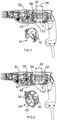
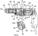
- Figures 1 to 3 each show a hammer drill, each of which forms part of a range of hammer drills.
- each of the three drills are in line hammer drills which comprise an electric motor 2 having a rotor 4 mounted within a stator 6.
- the motor 2 is powered via an electric cable 8 which connects to the motor via an electric switch 10. Depression of the switch causes the rotor 4 to rotate.
- a fan 44 is mounted on the output spindle 12 of the motor to draw air over the motor 2.
- the output spindle 12 of the motor comprises teeth which mesh with a gear 14 on an intermediate shaft 16 to rotatingly drive the intermediate shaft 16.
- a wobble bearing 18 is mounted on the intermediate shaft 16 which, when activated, is rotationally driven by the intermediate shaft 16 to reciprocatingly drive a piston 20 located within a hollow spindle 22.
- the piston reciprocatingly drives a ram 24 via an air cushion.
- the ram 24 in turn repetitively strikes a beat piece 26 which strikes the end of a cutting tool when held in a tool holder 28 attached to the end of the hollow spindle 22 at the front of the transmission.
- Also mounted on the intermediate shaft 16 is a second gear 30 which meshes with a third gear 32 mounted on the hollow spindle 22.
- the intermediate shaft 16 rotationally drives the hollow spindle 22 via the second and third gears, the third gear 32 driving the hollow spindle 22 via a torque clutch 36.
- Rotation of the hollow spindle 22 results in the rotation of the tool holder 28.
- the wobble bearing 18 and rotary drive are activated via a mode change mechanism 40. The operation of such a hammer drill is well known in art and therefore will not be discussed any further.
- the electric motor 2 and switch 10 are located within a motor housing 50 which also forms a support handle by which the operator holds the hammer drill.
- the transmission mechanism comprising the hammer mechanism and rotary drive are located within a transmission housing 52 with the tool holder mounted on the front of the transmission housing 50. Sandwiched between the motor housing 50 and the transmission housing 52 is an intermediate housing 54.
- the size of the motor 2 in each of three hammer drills in Figures 1 to 3 is different. This is due to the fact that the stack length of each of the motors is different.
- the motor 2 has a stack length 56 of 35mm.
- the motor 2 has a stack length 58 of 40mm.
- the motor 2 has a stack length 60 of 45mm.
- the output spindle 12 of the motor projects into the intermediate housing 54 through an aperture 120.
- the fan 44 is mounted on the output spindle 12 inside of the intermediate housing 54, the intermediate housing 54 surrounding, at least in part, surrounding the fan 44.
- the intermediate section 54 acts as a fan baffle, guiding the air around the fan 44.
- the fan 44 used with all three hammer drills with the three motors 2 of different stack lengths is the same design. As such, the overall length of the intermediate housing 54 in each of the drills remains the same.
- the shape of the motor housing 50 is identical even though the sizes of the motors, due to varying stack lengths, vary.
- the position of the intermediate housing 54 and fan 44 need to move forward relative to the motor housing 50.
- the transmission housing 52 then needs to be moved forward, relative to the motor 50 housing to enable the transmission mechanism to be positioned further forward. Therefore, different designs of intermediate housings 54 are used in each of the drills order to accommodate the different positions of the transmission housing 52. This results in the shape in the intermediate housings 54 changing with motors 2 having different stack lengths.
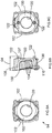
- the motor housing 50 connects directly to the transmission housing 52. Therefore the first intermediate housing 54 (shown in Figures 4A to 4C ) for this drill provides a back wall 70 as part of the fan baffle, two side grills 72 with apertures 74, which fit into an aperture formed between the transmission housing 52 and motor housing 50 through which air expelled from the rotating fan 44 can exit the hammer drill and two side walls 76 which locate internally of the entrance of the motor housing 50 and which act as part of the fan baffle.
- the motor housing 50 is connected via the intermediate housing 54 to the transmission housing 52 to enable the transmission housing 52 to be moved forward relative to the motor housing 50. Therefore, the second intermediate housing 54 (shown in Figures 5A to 5C ) provides a back wall 80 as part of the fan baffle, two side grills 82 with apertures 84, the width 86 of which is larger than the grill 72 of the first intermediate housing 54 to accommodate the forward position of the transmission housing 52, which fit into gaps formed between the transmission housing 52 and motor housing 50 and through which air expelled from the rotating fan 44 can exit the hammer drill, two side walls 88 which are smaller than the walls 76 of the first intermediate housing 54 and which locate internally of the entrance of the motor housing 50 and which act as part of the fan baffle, and two external walls 90, 92 located at the top and bottom and which fill the gap between the motor housing 50 and transmission housing 52.
- the motor housing 50 is connected via the intermediate housing 54 to the transmission housing 52 to enable the transmission housing 52 to be moved even further forward relative to the motor housing 50.
- the third intermediate housing 54 (shown in Figures 6A to 6C ) provides a back wall 100 as part of the fan baffle, two side grills 102 with apertures 104, the width 106 of which is larger than the grills 72, 82 of the first and second intermediate housings 54 to accommodate the forward position of the transmission housing 54 and which fit into gaps formed between the transmission housing 52 and motor housing 50 and through which air expelled from the rotating fan 44 can exit the hammer drill, two side walls 107 which are smaller than those of the first and second intermediate housings 54 and which locate internally of the entrance of the motor housing 50 and which act as part of the fan baffle and two external walls 108, 110 located at the top and bottom between the motor housing 50 and transmission housing 52 which are longer in length than those of the second intermediate housing 54 and which fill the larger gap between the motor housing 50 and transmission housing 52.
- the length of the external walls 108, 110 and the increase in the width of the grills 102 is the same as the increase in the stack length of the motor 2 compared with the stack length of the motor in
- intermediate housing 54 The cost of intermediate housing 54 is substantially less than that of the motor housing 50. Therefore the use of differing intermediate housing 54 to enable the same motor housing 50 to utilized on all of the hammer drills in a range decreases cost and increases simplicity. It also enables a standardized external look to be generated across the range.
- the intermediate housings 54 also provide support for the front of the stator 6 of the motor 2 via two rubber supports 122 which connect between the rear of the rear walls 70, 80, 100 of the intermediate housings and the front end of the stators 6 of the motors 2.
- the shape of the transmission housing 52 is identical whilst the shape of the transmission housing 52 of the hammer drill figure 3 is different to accommodate a larger transmission mechanism to drive a larger tool holder.
Landscapes
- Engineering & Computer Science (AREA)
- Mechanical Engineering (AREA)
- Drilling And Boring (AREA)
- Percussive Tools And Related Accessories (AREA)
Claims (10)
- Sortiment von Elektrowerkzeugen, das wenigstens zwei Elektrowerkzeuge umfasst, wobei jedes Elektrowerkzeug umfasst:ein Motorgehäuse (50) und ein Getriebegehäuse (52);einen elektrischen Motor (2), der innerhalb des Motorgehäuses (50) montiert ist;einen innerhalb des Getriebegehäuses (52) montierten Getriebemechanismus, der einen Drehausgang des Motors verwendet, um ein Schneidwerkzeug anzutreiben;ein Zwischengehäuse (54), das zwischen das Motorgehäuse und das Getriebegehäuse zwischengesetzt ist,wobei:das Motorgehäuse (50) jedes Elektrowerkzeugs dieselbe Form aufweist wie das Motorgehäuse (50) in jedem anderen Elektrowerkzeug in dem Sortiment, so dass die Form des Motorgehäuses (50) in jedem Elektrowerkzeug identisch ist, und die Länge des elektrischen Motors (2) in jedem der Elektrowerkzeuge sich von der Länge der elektrischen Motoren in den anderen Elektrowerkzeugen in dem Sortiment unterscheidet;wobei die Position des Getriebegehäuses (52) relativ zu dem Motorgehäuse (50) in jedem Elektrowerkzeug sich von jedem anderen Elektrowerkzeug in dem Sortiment unterscheidet, um den Unterschied in der Länge des elektrischen Motors (2) in demjenigen Elektrowerkzeug unterzubringen, wobei die Form des Zwischengehäuses (54) in jedem Elektrowerkzeug relativ zu den anderen Zwischengehäusen (54) variiert, um die unterschiedlichen Positionen der Getriebegehäuse (52) relativ zu den Motorgehäusen (50) unterzubringen;wobei in wenigstens einem der Elektrowerkzeuge in dem Sortiment das Motorgehäuse (50) über das Zwischengehäuse (54) mit dem Getriebegehäuse (52) verbunden ist, um zu ermöglichen, dass das Getriebegehäuse (52) relativ zu dem Motorgehäuse (50) nach vorn bewegt wird;wobei in wenigstens einem Elektrowerkzeug das Zwischengehäuse einen Teil einer externen Wand (90, 92, 108, 110) des Gehäuses des wenigstens einen Elektrowerkzeugs zwischen dem Motorgehäuse (50) und dem Getriebegehäuse (52) bildet;dadurch gekennzeichnet, dass die Längen (64) aller Zwischengehäuse (54) im Wesentlichen dieselben sind,und wobei die Länge der externen Wand (90, 92, 108, 110) über das Sortiment in Proportion zu der Zunahme in der Länge des Motors (2) über das Sortiment zunimmt.
- Sortiment von Elektrowerkzeugen nach Anspruch 1, wobei die Ausgestaltungen der Getriebegehäuse (52) von wenigstens zwei der Elektrowerkzeuge in dem Sortiment dieselben sind.
- Sortiment von Elektrowerkzeugen nach einem der vorstehenden Ansprüche, wobei ein Gebläse (44) drehbar in den Zwischengehäusen (54) in jedem der Elektrowerkzeuge montiert ist, um den Motor (2) desjenigen Elektrowerkzeugs zu kühlen, wobei jedes Zwischengehäuse (54) wenigstens einen Teil eines Gebläseablenkblechs bildet.
- Sortiment von Elektrowerkzeugen nach Anspruch 3, wobei jedes der Zwischengehäuse eine Mündung (120) umfasst, durch welche das Gebläse (44) Luft von dem Motorgehäuse (50) in das Zwischengehäuse (54) zieht.
- Sortiment von Elektrowerkzeugen nach Anspruch 4, wobei in jedem der Elektrowerkzeuge die Ausgangsspindel (12) des Motors (2) durch die Mündung (120) in die Zwischensektion (54) hervorsteht, wobei das Gebläse (44) auf die Spindel (12) montiert ist.
- Sortiment von Elektrowerkzeugen nach einem der Ansprüche 3 bis 5, wobei jedes der Zwischengehäuse (54) Mündungen (74, 84, 104) umfasst, durch welche das Gebläse (44) Luft aus den Zwischengehäusen (54) und aus den Elektrowerkzeugen ausstößt.
- Sortiment von Elektrowerkzeugen nach einem der vorstehenden Ansprüche, wobei die Stapellänge jedes der Motoren (2) der Elektrowerkzeuge unterschiedlich ist.
- Sortiment von Elektrowerkzeugen nach einem der vorstehenden Ansprüche, wobei jeder der Motoren einen Rotor (4) und einen Stator (6) umfasst, wobei die Zwischengehäuse (54) eine Lagerung für die Vorderseite der Statoren (6) bereitstellen.
- Sortiment von Elektrowerkzeugen nach Anspruch 8, wobei jedes der Zwischengehäuse die Statoren (6) unter Verwendung wenigstens eines Gummilagers (122) lagert, das zwischen den Statoren (6) und den Zwischengehäusen (54) montiert ist.
- Sortiment von Elektrowerkzeugen nach einem der vorstehenden Ansprüche, wobei die Elektrowerkzeuge Bohrhämmer sind.
Applications Claiming Priority (1)
| Application Number | Priority Date | Filing Date | Title |
|---|---|---|---|
| GBGB1413008.2A GB201413008D0 (en) | 2014-07-23 | 2014-07-23 | A range of power tools |
Publications (2)
| Publication Number | Publication Date |
|---|---|
| EP2977134A1 EP2977134A1 (de) | 2016-01-27 |
| EP2977134B1 true EP2977134B1 (de) | 2019-06-26 |
Family
ID=51494978
Family Applications (1)
| Application Number | Title | Priority Date | Filing Date |
|---|---|---|---|
| EP15177859.4A Active EP2977134B1 (de) | 2014-07-23 | 2015-07-22 | Reihe von elektrowerkzeugen |
Country Status (4)
| Country | Link |
|---|---|
| US (2) | US10807226B2 (de) |
| EP (1) | EP2977134B1 (de) |
| AU (1) | AU2015205895B2 (de) |
| GB (1) | GB201413008D0 (de) |
Families Citing this family (3)
| Publication number | Priority date | Publication date | Assignee | Title |
|---|---|---|---|---|
| US9776296B2 (en) | 2008-05-09 | 2017-10-03 | Milwaukee Electric Tool Corporation | Power tool dust collector |
| SE1851031A1 (en) * | 2018-08-31 | 2020-03-01 | Husqvarna Ab | Power tool |
| CN115570179A (zh) * | 2021-07-06 | 2023-01-06 | 南京泉峰科技有限公司 | 电钻及电动工具 |
Family Cites Families (78)
| Publication number | Priority date | Publication date | Assignee | Title |
|---|---|---|---|---|
| US2155082A (en) * | 1937-03-23 | 1939-04-18 | Black & Decker Mfg Co | Portable electric tool and casing |
| US2396007A (en) * | 1944-06-16 | 1946-03-05 | Singer Mfg Co | Portable electric drill |
| US2456571A (en) | 1947-09-13 | 1948-12-14 | Singer Mfg Co | Portable electric tool |
| DE1944660C3 (de) | 1969-09-03 | 1980-04-03 | C. & E. Fein Gmbh & Co, 7000 Stuttgart | Elektrowerkzeug |
| US3665228A (en) * | 1970-05-15 | 1972-05-23 | Murphy Ind Inc G W | Modular design-double insulated field |
| US3699655A (en) * | 1971-01-18 | 1972-10-24 | Rockwell Mfg Co | Power driven hand tool |
| US3802075A (en) * | 1971-01-18 | 1974-04-09 | Rockwell International Corp | Power driven hedge trimmer |
| US3730281A (en) * | 1971-06-07 | 1973-05-01 | Black & Decker Mfg Co | Drill hammer-drill mechanism for power tool |
| US3916233A (en) * | 1971-11-18 | 1975-10-28 | Licentia Gmbh | Electrical machine |
| DE2158118B2 (de) | 1971-11-24 | 1977-10-27 | Robert Bosch Gmbh, 7000 Stuttgart | Zweigang-handbohrmaschine |
| US3908139A (en) * | 1974-06-10 | 1975-09-23 | Singer Co | Portable power tools |
| JPS56155751U (de) * | 1980-04-23 | 1981-11-20 | ||
| DE8130338U1 (de) | 1981-10-16 | 1982-03-11 | Kraus, Kurt, 4933 Blomberg | Fremdbeluefteter elektromotorischer antrieb |
| SE443940B (sv) * | 1982-09-22 | 1986-03-17 | Atlas Copco Ab | Slagverktyg drivet av utbytbar motordel |
| DE3436734A1 (de) | 1984-10-06 | 1986-04-10 | Licentia Patent-Verwaltungs-Gmbh, 6000 Frankfurt | Elektrowerkzeug mit in einem aus kunststoff bestehenden gehaeuse untergebrachten antriebsmotor |
| US4730134A (en) * | 1987-05-28 | 1988-03-08 | The Singer Company | Portable power tool with combination bearing plate, nut plate and auxiliary handle mount |
| DE3824234A1 (de) * | 1988-07-16 | 1990-01-25 | Bosch Gmbh Robert | Handwerkzeugmaschine mit durchzugsbelueftetem antriebsmotor |
| DE59008112D1 (de) * | 1989-07-15 | 1995-02-09 | Kress Elektrik Gmbh & Co | Elektrowerkzeug. |
| DE4004464A1 (de) | 1989-07-15 | 1991-01-24 | Kress Elektrik Gmbh & Co | Elektrowerkzeug |
| US5475277A (en) * | 1993-07-21 | 1995-12-12 | Fluidmaster, Inc. | Differential torque motor |
| DE19511114C1 (de) * | 1995-03-25 | 1996-08-29 | Grundfos As | Elektromotor |
| US5709136A (en) * | 1996-02-25 | 1998-01-20 | Mcdonnell Douglas Corporation | Power driven tools |
| DE19631517A1 (de) | 1996-08-03 | 1998-02-05 | Wacker Werke Kg | Von einem Elektromotor angetriebenes, an Einphasenwechselstrom anschließbares, drehzahlvariables, handgehaltenes Elektrowerkzeug |
| US5763969A (en) | 1996-11-14 | 1998-06-09 | Reliance Electric Industrial Company | Integrated electric motor and drive system with auxiliary cooling motor and asymmetric heat sink |
| DE29620393U1 (de) | 1996-11-25 | 1998-03-26 | Robert Bosch Gmbh, 70469 Stuttgart | Handwerkzeugmaschine |
| US5749704A (en) | 1997-01-06 | 1998-05-12 | Wagner Spray Tech Corporation | Heat gun fan assembly |
| EP0953128A4 (de) | 1997-01-16 | 2000-03-29 | American Precision Ind | Modulare halterungsanordnung für motor und getriebe |
| DE19839963A1 (de) | 1998-09-02 | 2000-03-09 | Hilti Ag | Elektrowerkzeug |
| JP2000153473A (ja) | 1998-11-19 | 2000-06-06 | Makita Corp | 打撃工具 |
| DE19924552A1 (de) | 1999-05-28 | 2000-11-30 | Hilti Ag | Elektrisch betreibbares Handgerät |
| IT1309310B1 (it) | 1999-06-30 | 2002-01-22 | Hsd Srl | Elettromandrino. |
| GB0008465D0 (en) | 2000-04-07 | 2000-05-24 | Black & Decker Inc | Rotary hammer mode change mechanism |
| US6794788B1 (en) * | 2000-05-26 | 2004-09-21 | Schlumberger Technology Corporation | Modular motor and housing |
| GB2385017B (en) | 2002-02-08 | 2005-06-29 | Black & Decker Inc | Drilling and/or hammering tool |
| JP4075540B2 (ja) | 2002-09-10 | 2008-04-16 | 松下電工株式会社 | 電動工具 |
| DE10242414A1 (de) | 2002-09-12 | 2004-03-25 | Hilti Ag | Elektrowerkzeugmaschine mit Gebläse |
| GB2392874A (en) * | 2002-09-13 | 2004-03-17 | Pryor Edward & Son | High speed marker having a marking head mounted on a drive screw for linear movement in a first axis and rotatable thereon for movement in a second axis |
| DE10256547A1 (de) * | 2002-12-04 | 2004-06-24 | Hilti Ag | Mehrteilige Lagerbrücke |
| DE10261572A1 (de) | 2002-12-23 | 2004-07-01 | Robert Bosch Gmbh | Elektrohandwerkzeugmaschine |
| US7063170B2 (en) | 2003-02-26 | 2006-06-20 | Black & Decker Inc. | Flexible power tool motor pack and method of making the same |
| US6940198B2 (en) * | 2003-07-24 | 2005-09-06 | A. O. Smith Corporation | Brushless permanent magnet machine with reduced cogging and torque ripple and method of producing the same |
| US7893583B2 (en) * | 2003-09-05 | 2011-02-22 | Black & Decker Inc. | Power tools with motor having a multi-piece stator |
| DE102004055268A1 (de) | 2004-11-17 | 2006-05-18 | Robert Bosch Gmbh | Handwerkzeugmaschine |
| EP1674743B1 (de) * | 2004-12-23 | 2014-01-22 | Black & Decker Inc. | Antriebsmechanismus für ein Kraftwerkzeug |
| DE102005007545B4 (de) | 2005-02-18 | 2019-01-31 | Robert Bosch Gmbh | Vorrichtung und Verfahren zur Kühlung einer Elektronik |
| DE102005007546A1 (de) | 2005-02-18 | 2006-08-24 | Robert Bosch Gmbh | Elektrowerkzeugmaschine |
| US20070050992A1 (en) * | 2005-09-06 | 2007-03-08 | Fisher David B | System and apparatus for attaching an electric motor to a power tool |
| JP4692288B2 (ja) | 2006-01-11 | 2011-06-01 | 日立工機株式会社 | 電動工具及びその組立方法 |
| DE102006000084A1 (de) | 2006-02-20 | 2007-08-23 | Hilti Ag | Handwerkzeuggerät mit Erdung |
| US7988538B2 (en) | 2006-10-13 | 2011-08-02 | Black & Decker Inc. | Large angle grinder |
| US7719230B2 (en) * | 2006-10-27 | 2010-05-18 | Snap-On Incorporated | Kit of power tools |
| US7609025B2 (en) * | 2006-11-03 | 2009-10-27 | Snap-On Incorporated | Kit of power tools |
| DE102006000543A1 (de) | 2006-12-21 | 2008-06-26 | Hilti Ag | Handwerkzeuggerät mit einem mehrteiligen Gehäuse |
| DE102007017243A1 (de) * | 2007-04-12 | 2008-10-16 | Robert Bosch Gmbh | Werkzeugmaschine, insbesondere Handwerkzeugmaschine |
| DE102007000290A1 (de) | 2007-05-24 | 2008-11-27 | Hilti Aktiengesellschaft | Elektrisches Handwerkzeuggerät mit Elektronikkühlung |
| DE102007060057A1 (de) * | 2007-12-13 | 2009-06-18 | Robert Bosch Gmbh | Handwerkzeugmaschine |
| DE102008009233A1 (de) | 2008-02-04 | 2009-08-06 | REMS-WERK Christian Föll und Söhne GmbH & Co KG | Antriebsgerät für Werkzeuge, vorzugsweise für Kernbohrkronen |
| DE102008001258A1 (de) | 2008-04-18 | 2009-10-22 | Robert Bosch Gmbh | Werkzeugmaschine mit elektrischem Antriebsmotor |
| DE102008001266A1 (de) * | 2008-04-18 | 2009-10-22 | Robert Bosch Gmbh | Adapterteil für eine Werkzeugmaschine |
| US7923875B2 (en) | 2008-04-25 | 2011-04-12 | A.O. Smith Corporation | Assembly for an electric machine |
| US7868565B2 (en) * | 2008-06-20 | 2011-01-11 | Minebea Co., Ltd. | Linear actuator motor selection method and devices |
| US8508084B2 (en) * | 2008-06-26 | 2013-08-13 | Techtronic Power Tools Technology Limited | Power tool including hybrid electric motor design |
| US7732955B2 (en) | 2008-08-18 | 2010-06-08 | Black & Decker Inc. | Power tool with motor air flow path control |
| DE102008059599A1 (de) | 2008-11-28 | 2010-06-02 | Aeg Electric Tools Gmbh | Elektrowerkzeug |
| JP5416397B2 (ja) | 2008-12-19 | 2014-02-12 | 株式会社マキタ | 作業工具 |
| JP5472683B2 (ja) | 2009-05-11 | 2014-04-16 | 日立工機株式会社 | 電動工具 |
| DE102009021925B4 (de) | 2009-05-19 | 2018-11-22 | Metabowerke Gmbh | Elektrohandwerkzeuggerät |
| DE102009026519A1 (de) | 2009-05-27 | 2010-12-02 | Robert Bosch Gmbh | Werkzeugmaschine, insbesondere Handwerkzeugmaschine |
| EP2337186B1 (de) | 2009-12-18 | 2016-09-21 | Ziehl-Abegg Se | Außenläufer-Elektromotor |
| DE102010004724A1 (de) | 2010-01-15 | 2011-07-21 | Wacker Neuson SE, 80809 | Bohr- und/oder Schlaghammer mit Kühlung von Gerätekomponenten |
| US8525375B2 (en) | 2010-03-23 | 2013-09-03 | Hamilton Sundstrand Corporation | Cooling arrangement for end turns and stator in an electric machine |
| DE102010013756A1 (de) | 2010-03-31 | 2011-10-06 | Andreas Stihl Ag & Co. Kg | Handgeführtes Arbeitsgerät |
| DE102010029779B4 (de) | 2010-06-08 | 2012-04-05 | Hilti Aktiengesellschaft | Lüfter, Elektromotor und Werkzeugmaschine |
| CN103098356B (zh) * | 2010-08-04 | 2016-08-03 | 斯泰伦博斯大学 | 滑差永磁体机构 |
| DE102010047008A1 (de) * | 2010-09-30 | 2012-04-05 | Ims Gear Gmbh | Verbindungsstruktur zur mechanischen Verbindung eines ersten Gehäuses mit einem zweiten Gehäuse |
| US9197109B2 (en) | 2012-03-08 | 2015-11-24 | Stainless Motors, Inc. | Electric motor configured for facilitated washability |
| US20130299207A1 (en) * | 2012-05-10 | 2013-11-14 | Black & Decker, Inc. | Power tool cooling |
| US9718180B2 (en) * | 2013-05-09 | 2017-08-01 | Black & Decker Inc. | Power tool having improved motor and controller cooling |
-
2014
- 2014-07-23 GB GBGB1413008.2A patent/GB201413008D0/en not_active Ceased
-
2015
- 2015-07-15 US US14/799,865 patent/US10807226B2/en active Active
- 2015-07-22 EP EP15177859.4A patent/EP2977134B1/de active Active
- 2015-07-23 AU AU2015205895A patent/AU2015205895B2/en not_active Expired - Fee Related
-
2019
- 2019-10-31 US US16/669,964 patent/US11433526B2/en active Active
Non-Patent Citations (1)
| Title |
|---|
| None * |
Also Published As
| Publication number | Publication date |
|---|---|
| US20200061798A1 (en) | 2020-02-27 |
| US11433526B2 (en) | 2022-09-06 |
| EP2977134A1 (de) | 2016-01-27 |
| US20160023346A1 (en) | 2016-01-28 |
| AU2015205895A1 (en) | 2016-02-11 |
| AU2015205895B2 (en) | 2019-06-27 |
| US10807226B2 (en) | 2020-10-20 |
| GB201413008D0 (en) | 2014-09-03 |
Similar Documents
| Publication | Publication Date | Title |
|---|---|---|
| EP2979820B1 (de) | Knopfanordnung für moduswechsel | |
| US9126320B2 (en) | Power tool | |
| US10040178B2 (en) | Power tool and rotary impact tool | |
| US8484827B2 (en) | Method of assembling a drilling and/or hammering tool | |
| EP1690642B1 (de) | Handgehaltene Schlagmaschine | |
| US11433526B2 (en) | Power tool having an intermediate housing | |
| EP2014421B1 (de) | Bohrhammer | |
| EP2921264B1 (de) | Bohrhammer | |
| EP2189246A3 (de) | Werkzeugmaschine | |
| EP1825963B1 (de) | Schlagendes Handwerkzeuggerät | |
| EP2486998A3 (de) | Schneidewerkzeuge | |
| CN102189284A (zh) | 锤钻装置 | |
| US11986929B2 (en) | Handheld machine tool, in particular impact driver | |
| CN101641187A (zh) | 手持式工具机 | |
| EP3260238B1 (de) | Motorendkappe | |
| JP5574156B2 (ja) | ボルト締付機 | |
| JP2018103318A (ja) | 電動工具 | |
| JP2016068205A (ja) | 電動工具 | |
| JP7070337B2 (ja) | 電気機器 | |
| EP2933060A2 (de) | Pneumatisches werkzeug | |
| JP2013244561A (ja) | 電動工具 | |
| WO2012024842A1 (en) | Hand-held power tool | |
| JP2013091117A (ja) | 打撃工具 | |
| JP2018122420A (ja) | 手持ち式電動工具 |
Legal Events
| Date | Code | Title | Description |
|---|---|---|---|
| PUAI | Public reference made under article 153(3) epc to a published international application that has entered the european phase |
Free format text: ORIGINAL CODE: 0009012 |
|
| AK | Designated contracting states |
Kind code of ref document: A1 Designated state(s): AL AT BE BG CH CY CZ DE DK EE ES FI FR GB GR HR HU IE IS IT LI LT LU LV MC MK MT NL NO PL PT RO RS SE SI SK SM TR |
|
| AX | Request for extension of the european patent |
Extension state: BA ME |
|
| 17P | Request for examination filed |
Effective date: 20160513 |
|
| RBV | Designated contracting states (corrected) |
Designated state(s): AL AT BE BG CH CY CZ DE DK EE ES FI FR GB GR HR HU IE IS IT LI LT LU LV MC MK MT NL NO PL PT RO RS SE SI SK SM TR |
|
| GRAP | Despatch of communication of intention to grant a patent |
Free format text: ORIGINAL CODE: EPIDOSNIGR1 |
|
| STAA | Information on the status of an ep patent application or granted ep patent |
Free format text: STATUS: GRANT OF PATENT IS INTENDED |
|
| INTG | Intention to grant announced |
Effective date: 20190412 |
|
| GRAS | Grant fee paid |
Free format text: ORIGINAL CODE: EPIDOSNIGR3 |
|
| GRAA | (expected) grant |
Free format text: ORIGINAL CODE: 0009210 |
|
| STAA | Information on the status of an ep patent application or granted ep patent |
Free format text: STATUS: THE PATENT HAS BEEN GRANTED |
|
| AK | Designated contracting states |
Kind code of ref document: B1 Designated state(s): AL AT BE BG CH CY CZ DE DK EE ES FI FR GB GR HR HU IE IS IT LI LT LU LV MC MK MT NL NO PL PT RO RS SE SI SK SM TR |
|
| REG | Reference to a national code |
Ref country code: GB Ref legal event code: FG4D |
|
| REG | Reference to a national code |
Ref country code: CH Ref legal event code: EP |
|
| REG | Reference to a national code |
Ref country code: AT Ref legal event code: REF Ref document number: 1147729 Country of ref document: AT Kind code of ref document: T Effective date: 20190715 |
|
| REG | Reference to a national code |
Ref country code: IE Ref legal event code: FG4D |
|
| REG | Reference to a national code |
Ref country code: DE Ref legal event code: R096 Ref document number: 602015032592 Country of ref document: DE |
|
| REG | Reference to a national code |
Ref country code: NL Ref legal event code: MP Effective date: 20190626 |
|
| PG25 | Lapsed in a contracting state [announced via postgrant information from national office to epo] |
Ref country code: FI Free format text: LAPSE BECAUSE OF FAILURE TO SUBMIT A TRANSLATION OF THE DESCRIPTION OR TO PAY THE FEE WITHIN THE PRESCRIBED TIME-LIMIT Effective date: 20190626 Ref country code: HR Free format text: LAPSE BECAUSE OF FAILURE TO SUBMIT A TRANSLATION OF THE DESCRIPTION OR TO PAY THE FEE WITHIN THE PRESCRIBED TIME-LIMIT Effective date: 20190626 Ref country code: AL Free format text: LAPSE BECAUSE OF FAILURE TO SUBMIT A TRANSLATION OF THE DESCRIPTION OR TO PAY THE FEE WITHIN THE PRESCRIBED TIME-LIMIT Effective date: 20190626 Ref country code: SE Free format text: LAPSE BECAUSE OF FAILURE TO SUBMIT A TRANSLATION OF THE DESCRIPTION OR TO PAY THE FEE WITHIN THE PRESCRIBED TIME-LIMIT Effective date: 20190626 Ref country code: NO Free format text: LAPSE BECAUSE OF FAILURE TO SUBMIT A TRANSLATION OF THE DESCRIPTION OR TO PAY THE FEE WITHIN THE PRESCRIBED TIME-LIMIT Effective date: 20190926 Ref country code: LT Free format text: LAPSE BECAUSE OF FAILURE TO SUBMIT A TRANSLATION OF THE DESCRIPTION OR TO PAY THE FEE WITHIN THE PRESCRIBED TIME-LIMIT Effective date: 20190626 |
|
| REG | Reference to a national code |
Ref country code: LT Ref legal event code: MG4D |
|
| PG25 | Lapsed in a contracting state [announced via postgrant information from national office to epo] |
Ref country code: RS Free format text: LAPSE BECAUSE OF FAILURE TO SUBMIT A TRANSLATION OF THE DESCRIPTION OR TO PAY THE FEE WITHIN THE PRESCRIBED TIME-LIMIT Effective date: 20190626 Ref country code: BG Free format text: LAPSE BECAUSE OF FAILURE TO SUBMIT A TRANSLATION OF THE DESCRIPTION OR TO PAY THE FEE WITHIN THE PRESCRIBED TIME-LIMIT Effective date: 20190926 Ref country code: GR Free format text: LAPSE BECAUSE OF FAILURE TO SUBMIT A TRANSLATION OF THE DESCRIPTION OR TO PAY THE FEE WITHIN THE PRESCRIBED TIME-LIMIT Effective date: 20190927 Ref country code: LV Free format text: LAPSE BECAUSE OF FAILURE TO SUBMIT A TRANSLATION OF THE DESCRIPTION OR TO PAY THE FEE WITHIN THE PRESCRIBED TIME-LIMIT Effective date: 20190626 |
|
| REG | Reference to a national code |
Ref country code: AT Ref legal event code: MK05 Ref document number: 1147729 Country of ref document: AT Kind code of ref document: T Effective date: 20190626 |
|
| PG25 | Lapsed in a contracting state [announced via postgrant information from national office to epo] |
Ref country code: CZ Free format text: LAPSE BECAUSE OF FAILURE TO SUBMIT A TRANSLATION OF THE DESCRIPTION OR TO PAY THE FEE WITHIN THE PRESCRIBED TIME-LIMIT Effective date: 20190626 Ref country code: RO Free format text: LAPSE BECAUSE OF FAILURE TO SUBMIT A TRANSLATION OF THE DESCRIPTION OR TO PAY THE FEE WITHIN THE PRESCRIBED TIME-LIMIT Effective date: 20190626 Ref country code: SK Free format text: LAPSE BECAUSE OF FAILURE TO SUBMIT A TRANSLATION OF THE DESCRIPTION OR TO PAY THE FEE WITHIN THE PRESCRIBED TIME-LIMIT Effective date: 20190626 Ref country code: AT Free format text: LAPSE BECAUSE OF FAILURE TO SUBMIT A TRANSLATION OF THE DESCRIPTION OR TO PAY THE FEE WITHIN THE PRESCRIBED TIME-LIMIT Effective date: 20190626 Ref country code: NL Free format text: LAPSE BECAUSE OF FAILURE TO SUBMIT A TRANSLATION OF THE DESCRIPTION OR TO PAY THE FEE WITHIN THE PRESCRIBED TIME-LIMIT Effective date: 20190626 Ref country code: EE Free format text: LAPSE BECAUSE OF FAILURE TO SUBMIT A TRANSLATION OF THE DESCRIPTION OR TO PAY THE FEE WITHIN THE PRESCRIBED TIME-LIMIT Effective date: 20190626 Ref country code: PT Free format text: LAPSE BECAUSE OF FAILURE TO SUBMIT A TRANSLATION OF THE DESCRIPTION OR TO PAY THE FEE WITHIN THE PRESCRIBED TIME-LIMIT Effective date: 20191028 |
|
| PG25 | Lapsed in a contracting state [announced via postgrant information from national office to epo] |
Ref country code: IT Free format text: LAPSE BECAUSE OF FAILURE TO SUBMIT A TRANSLATION OF THE DESCRIPTION OR TO PAY THE FEE WITHIN THE PRESCRIBED TIME-LIMIT Effective date: 20190626 Ref country code: ES Free format text: LAPSE BECAUSE OF FAILURE TO SUBMIT A TRANSLATION OF THE DESCRIPTION OR TO PAY THE FEE WITHIN THE PRESCRIBED TIME-LIMIT Effective date: 20190626 Ref country code: IS Free format text: LAPSE BECAUSE OF FAILURE TO SUBMIT A TRANSLATION OF THE DESCRIPTION OR TO PAY THE FEE WITHIN THE PRESCRIBED TIME-LIMIT Effective date: 20191026 Ref country code: SM Free format text: LAPSE BECAUSE OF FAILURE TO SUBMIT A TRANSLATION OF THE DESCRIPTION OR TO PAY THE FEE WITHIN THE PRESCRIBED TIME-LIMIT Effective date: 20190626 |
|
| REG | Reference to a national code |
Ref country code: CH Ref legal event code: PL |
|
| PG25 | Lapsed in a contracting state [announced via postgrant information from national office to epo] |
Ref country code: TR Free format text: LAPSE BECAUSE OF FAILURE TO SUBMIT A TRANSLATION OF THE DESCRIPTION OR TO PAY THE FEE WITHIN THE PRESCRIBED TIME-LIMIT Effective date: 20190626 Ref country code: MC Free format text: LAPSE BECAUSE OF FAILURE TO SUBMIT A TRANSLATION OF THE DESCRIPTION OR TO PAY THE FEE WITHIN THE PRESCRIBED TIME-LIMIT Effective date: 20190626 |
|
| REG | Reference to a national code |
Ref country code: BE Ref legal event code: MM Effective date: 20190731 |
|
| PG25 | Lapsed in a contracting state [announced via postgrant information from national office to epo] |
Ref country code: PL Free format text: LAPSE BECAUSE OF FAILURE TO SUBMIT A TRANSLATION OF THE DESCRIPTION OR TO PAY THE FEE WITHIN THE PRESCRIBED TIME-LIMIT Effective date: 20190626 Ref country code: DK Free format text: LAPSE BECAUSE OF FAILURE TO SUBMIT A TRANSLATION OF THE DESCRIPTION OR TO PAY THE FEE WITHIN THE PRESCRIBED TIME-LIMIT Effective date: 20190626 |
|
| PG25 | Lapsed in a contracting state [announced via postgrant information from national office to epo] |
Ref country code: CH Free format text: LAPSE BECAUSE OF NON-PAYMENT OF DUE FEES Effective date: 20190731 Ref country code: BE Free format text: LAPSE BECAUSE OF NON-PAYMENT OF DUE FEES Effective date: 20190731 Ref country code: LI Free format text: LAPSE BECAUSE OF NON-PAYMENT OF DUE FEES Effective date: 20190731 Ref country code: IS Free format text: LAPSE BECAUSE OF FAILURE TO SUBMIT A TRANSLATION OF THE DESCRIPTION OR TO PAY THE FEE WITHIN THE PRESCRIBED TIME-LIMIT Effective date: 20200224 Ref country code: LU Free format text: LAPSE BECAUSE OF NON-PAYMENT OF DUE FEES Effective date: 20190722 |
|
| REG | Reference to a national code |
Ref country code: DE Ref legal event code: R097 Ref document number: 602015032592 Country of ref document: DE |
|
| PLBE | No opposition filed within time limit |
Free format text: ORIGINAL CODE: 0009261 |
|
| STAA | Information on the status of an ep patent application or granted ep patent |
Free format text: STATUS: NO OPPOSITION FILED WITHIN TIME LIMIT |
|
| PG2D | Information on lapse in contracting state deleted |
Ref country code: IS |
|
| PG25 | Lapsed in a contracting state [announced via postgrant information from national office to epo] |
Ref country code: FR Free format text: LAPSE BECAUSE OF NON-PAYMENT OF DUE FEES Effective date: 20190826 Ref country code: IE Free format text: LAPSE BECAUSE OF NON-PAYMENT OF DUE FEES Effective date: 20190722 |
|
| 26N | No opposition filed |
Effective date: 20200603 |
|
| PG25 | Lapsed in a contracting state [announced via postgrant information from national office to epo] |
Ref country code: SI Free format text: LAPSE BECAUSE OF FAILURE TO SUBMIT A TRANSLATION OF THE DESCRIPTION OR TO PAY THE FEE WITHIN THE PRESCRIBED TIME-LIMIT Effective date: 20190626 |
|
| PG25 | Lapsed in a contracting state [announced via postgrant information from national office to epo] |
Ref country code: CY Free format text: LAPSE BECAUSE OF FAILURE TO SUBMIT A TRANSLATION OF THE DESCRIPTION OR TO PAY THE FEE WITHIN THE PRESCRIBED TIME-LIMIT Effective date: 20190626 |
|
| PG25 | Lapsed in a contracting state [announced via postgrant information from national office to epo] |
Ref country code: HU Free format text: LAPSE BECAUSE OF FAILURE TO SUBMIT A TRANSLATION OF THE DESCRIPTION OR TO PAY THE FEE WITHIN THE PRESCRIBED TIME-LIMIT; INVALID AB INITIO Effective date: 20150722 Ref country code: MT Free format text: LAPSE BECAUSE OF FAILURE TO SUBMIT A TRANSLATION OF THE DESCRIPTION OR TO PAY THE FEE WITHIN THE PRESCRIBED TIME-LIMIT Effective date: 20190626 |
|
| PG25 | Lapsed in a contracting state [announced via postgrant information from national office to epo] |
Ref country code: MK Free format text: LAPSE BECAUSE OF FAILURE TO SUBMIT A TRANSLATION OF THE DESCRIPTION OR TO PAY THE FEE WITHIN THE PRESCRIBED TIME-LIMIT Effective date: 20190626 |
|
| PGFP | Annual fee paid to national office [announced via postgrant information from national office to epo] |
Ref country code: DE Payment date: 20250722 Year of fee payment: 11 |
|
| PGFP | Annual fee paid to national office [announced via postgrant information from national office to epo] |
Ref country code: GB Payment date: 20250724 Year of fee payment: 11 |