EP2977184B1 - Entree d'air de soufflage a commande de volume - Google Patents
Entree d'air de soufflage a commande de volume Download PDFInfo
- Publication number
- EP2977184B1 EP2977184B1 EP15002111.1A EP15002111A EP2977184B1 EP 2977184 B1 EP2977184 B1 EP 2977184B1 EP 15002111 A EP15002111 A EP 15002111A EP 2977184 B1 EP2977184 B1 EP 2977184B1
- Authority
- EP
- European Patent Office
- Prior art keywords
- throttle valve
- control unit
- preform
- blowing
- volume flow
- Prior art date
- Legal status (The legal status is an assumption and is not a legal conclusion. Google has not performed a legal analysis and makes no representation as to the accuracy of the status listed.)
- Active
Links
Images

Classifications
-
- B—PERFORMING OPERATIONS; TRANSPORTING
- B29—WORKING OF PLASTICS; WORKING OF SUBSTANCES IN A PLASTIC STATE IN GENERAL
- B29C—SHAPING OR JOINING OF PLASTICS; SHAPING OF MATERIAL IN A PLASTIC STATE, NOT OTHERWISE PROVIDED FOR; AFTER-TREATMENT OF THE SHAPED PRODUCTS, e.g. REPAIRING
- B29C49/00—Blow-moulding, i.e. blowing a preform or parison to a desired shape within a mould; Apparatus therefor
- B29C49/18—Blow-moulding, i.e. blowing a preform or parison to a desired shape within a mould; Apparatus therefor using several blowing steps
-
- B—PERFORMING OPERATIONS; TRANSPORTING
- B29—WORKING OF PLASTICS; WORKING OF SUBSTANCES IN A PLASTIC STATE IN GENERAL
- B29C—SHAPING OR JOINING OF PLASTICS; SHAPING OF MATERIAL IN A PLASTIC STATE, NOT OTHERWISE PROVIDED FOR; AFTER-TREATMENT OF THE SHAPED PRODUCTS, e.g. REPAIRING
- B29C49/00—Blow-moulding, i.e. blowing a preform or parison to a desired shape within a mould; Apparatus therefor
- B29C49/42—Component parts, details or accessories; Auxiliary operations
-
- B—PERFORMING OPERATIONS; TRANSPORTING
- B29—WORKING OF PLASTICS; WORKING OF SUBSTANCES IN A PLASTIC STATE IN GENERAL
- B29C—SHAPING OR JOINING OF PLASTICS; SHAPING OF MATERIAL IN A PLASTIC STATE, NOT OTHERWISE PROVIDED FOR; AFTER-TREATMENT OF THE SHAPED PRODUCTS, e.g. REPAIRING
- B29C49/00—Blow-moulding, i.e. blowing a preform or parison to a desired shape within a mould; Apparatus therefor
- B29C49/42—Component parts, details or accessories; Auxiliary operations
- B29C49/78—Measuring, controlling or regulating
-
- B—PERFORMING OPERATIONS; TRANSPORTING
- B29—WORKING OF PLASTICS; WORKING OF SUBSTANCES IN A PLASTIC STATE IN GENERAL
- B29C—SHAPING OR JOINING OF PLASTICS; SHAPING OF MATERIAL IN A PLASTIC STATE, NOT OTHERWISE PROVIDED FOR; AFTER-TREATMENT OF THE SHAPED PRODUCTS, e.g. REPAIRING
- B29C49/00—Blow-moulding, i.e. blowing a preform or parison to a desired shape within a mould; Apparatus therefor
- B29C49/42—Component parts, details or accessories; Auxiliary operations
- B29C49/78—Measuring, controlling or regulating
- B29C49/783—Measuring, controlling or regulating blowing pressure
-
- B—PERFORMING OPERATIONS; TRANSPORTING
- B29—WORKING OF PLASTICS; WORKING OF SUBSTANCES IN A PLASTIC STATE IN GENERAL
- B29C—SHAPING OR JOINING OF PLASTICS; SHAPING OF MATERIAL IN A PLASTIC STATE, NOT OTHERWISE PROVIDED FOR; AFTER-TREATMENT OF THE SHAPED PRODUCTS, e.g. REPAIRING
- B29C49/00—Blow-moulding, i.e. blowing a preform or parison to a desired shape within a mould; Apparatus therefor
- B29C49/42—Component parts, details or accessories; Auxiliary operations
- B29C49/78—Measuring, controlling or regulating
- B29C49/786—Temperature
-
- B—PERFORMING OPERATIONS; TRANSPORTING
- B29—WORKING OF PLASTICS; WORKING OF SUBSTANCES IN A PLASTIC STATE IN GENERAL
- B29C—SHAPING OR JOINING OF PLASTICS; SHAPING OF MATERIAL IN A PLASTIC STATE, NOT OTHERWISE PROVIDED FOR; AFTER-TREATMENT OF THE SHAPED PRODUCTS, e.g. REPAIRING
- B29C49/00—Blow-moulding, i.e. blowing a preform or parison to a desired shape within a mould; Apparatus therefor
- B29C49/42—Component parts, details or accessories; Auxiliary operations
- B29C49/62—Venting means
- B29C2049/6271—Venting means for venting blowing medium, e.g. using damper or silencer
-
- B—PERFORMING OPERATIONS; TRANSPORTING
- B29—WORKING OF PLASTICS; WORKING OF SUBSTANCES IN A PLASTIC STATE IN GENERAL
- B29C—SHAPING OR JOINING OF PLASTICS; SHAPING OF MATERIAL IN A PLASTIC STATE, NOT OTHERWISE PROVIDED FOR; AFTER-TREATMENT OF THE SHAPED PRODUCTS, e.g. REPAIRING
- B29C49/00—Blow-moulding, i.e. blowing a preform or parison to a desired shape within a mould; Apparatus therefor
- B29C49/42—Component parts, details or accessories; Auxiliary operations
- B29C49/78—Measuring, controlling or regulating
- B29C49/783—Measuring, controlling or regulating blowing pressure
- B29C2049/7831—Measuring, controlling or regulating blowing pressure characterised by pressure values or ranges
-
- B—PERFORMING OPERATIONS; TRANSPORTING
- B29—WORKING OF PLASTICS; WORKING OF SUBSTANCES IN A PLASTIC STATE IN GENERAL
- B29C—SHAPING OR JOINING OF PLASTICS; SHAPING OF MATERIAL IN A PLASTIC STATE, NOT OTHERWISE PROVIDED FOR; AFTER-TREATMENT OF THE SHAPED PRODUCTS, e.g. REPAIRING
- B29C49/00—Blow-moulding, i.e. blowing a preform or parison to a desired shape within a mould; Apparatus therefor
- B29C49/42—Component parts, details or accessories; Auxiliary operations
- B29C49/78—Measuring, controlling or regulating
- B29C49/783—Measuring, controlling or regulating blowing pressure
- B29C2049/7832—Blowing with two or more pressure levels
-
- B—PERFORMING OPERATIONS; TRANSPORTING
- B29—WORKING OF PLASTICS; WORKING OF SUBSTANCES IN A PLASTIC STATE IN GENERAL
- B29C—SHAPING OR JOINING OF PLASTICS; SHAPING OF MATERIAL IN A PLASTIC STATE, NOT OTHERWISE PROVIDED FOR; AFTER-TREATMENT OF THE SHAPED PRODUCTS, e.g. REPAIRING
- B29C2949/00—Indexing scheme relating to blow-moulding
- B29C2949/07—Preforms or parisons characterised by their configuration
- B29C2949/0715—Preforms or parisons characterised by their configuration the preform having one end closed
-
- B—PERFORMING OPERATIONS; TRANSPORTING
- B29—WORKING OF PLASTICS; WORKING OF SUBSTANCES IN A PLASTIC STATE IN GENERAL
- B29C—SHAPING OR JOINING OF PLASTICS; SHAPING OF MATERIAL IN A PLASTIC STATE, NOT OTHERWISE PROVIDED FOR; AFTER-TREATMENT OF THE SHAPED PRODUCTS, e.g. REPAIRING
- B29C49/00—Blow-moulding, i.e. blowing a preform or parison to a desired shape within a mould; Apparatus therefor
- B29C49/02—Combined blow-moulding and manufacture of the preform or the parison
- B29C49/06—Injection blow-moulding
-
- B—PERFORMING OPERATIONS; TRANSPORTING
- B29—WORKING OF PLASTICS; WORKING OF SUBSTANCES IN A PLASTIC STATE IN GENERAL
- B29C—SHAPING OR JOINING OF PLASTICS; SHAPING OF MATERIAL IN A PLASTIC STATE, NOT OTHERWISE PROVIDED FOR; AFTER-TREATMENT OF THE SHAPED PRODUCTS, e.g. REPAIRING
- B29C49/00—Blow-moulding, i.e. blowing a preform or parison to a desired shape within a mould; Apparatus therefor
- B29C49/28—Blow-moulding apparatus
- B29C49/30—Blow-moulding apparatus having movable moulds or mould parts
- B29C49/36—Blow-moulding apparatus having movable moulds or mould parts rotatable about one axis
-
- B—PERFORMING OPERATIONS; TRANSPORTING
- B29—WORKING OF PLASTICS; WORKING OF SUBSTANCES IN A PLASTIC STATE IN GENERAL
- B29C—SHAPING OR JOINING OF PLASTICS; SHAPING OF MATERIAL IN A PLASTIC STATE, NOT OTHERWISE PROVIDED FOR; AFTER-TREATMENT OF THE SHAPED PRODUCTS, e.g. REPAIRING
- B29C49/00—Blow-moulding, i.e. blowing a preform or parison to a desired shape within a mould; Apparatus therefor
- B29C49/42—Component parts, details or accessories; Auxiliary operations
- B29C49/4289—Valve constructions or configurations, e.g. arranged to reduce blowing fluid consumption
-
- B—PERFORMING OPERATIONS; TRANSPORTING
- B29—WORKING OF PLASTICS; WORKING OF SUBSTANCES IN A PLASTIC STATE IN GENERAL
- B29K—INDEXING SCHEME ASSOCIATED WITH SUBCLASSES B29B, B29C OR B29D, RELATING TO MOULDING MATERIALS OR TO MATERIALS FOR MOULDS, REINFORCEMENTS, FILLERS OR PREFORMED PARTS, e.g. INSERTS
- B29K2101/00—Use of unspecified macromolecular compounds as moulding material
- B29K2101/12—Thermoplastic materials
-
- B—PERFORMING OPERATIONS; TRANSPORTING
- B29—WORKING OF PLASTICS; WORKING OF SUBSTANCES IN A PLASTIC STATE IN GENERAL
- B29L—INDEXING SCHEME ASSOCIATED WITH SUBCLASS B29C, RELATING TO PARTICULAR ARTICLES
- B29L2031/00—Other particular articles
- B29L2031/712—Containers; Packaging elements or accessories, Packages
-
- B—PERFORMING OPERATIONS; TRANSPORTING
- B29—WORKING OF PLASTICS; WORKING OF SUBSTANCES IN A PLASTIC STATE IN GENERAL
- B29L—INDEXING SCHEME ASSOCIATED WITH SUBCLASS B29C, RELATING TO PARTICULAR ARTICLES
- B29L2031/00—Other particular articles
- B29L2031/712—Containers; Packaging elements or accessories, Packages
- B29L2031/7158—Bottles
Definitions
- the present invention relates to a method for controlling a blow molding machine for the production of a container from a thermoplastic material according to the preamble of claim 1 as well as a blow molding machine for the production of containers from a thermoplastic material according to the preamble of claim 12.
- a container usually a blown gas or a blown air is introduced into a thermally preconditioned preform made of thermoplastic material.
- the blow molding takes place in two stages.
- the pre-blowing - the preform is subjected to a first pressure of, for example, 10 bar, so that the temperature-conditioned material of the preform controlled and evenly expands and can be applied to the walls of the blow mold.
- the second phase the finished blowing - the pre-stretched preform is subjected to a second pressure of for example 40 bar, so that the material lies completely in the contours of the blow mold used.
- the blowing gas is introduced, for example via a throttle with a cross-section of, for example, 4 mm 2 in the preform.
- the adjustment of the throttle depends on various factors, such as the type of material of the container to be manufactured, the temperature profile with which the preform is thermally conditioned, the wall thickness of the preform and other parameters.
- the throttle width is typically set manually once and remains unchanged. A renewed manual change in the throttle cross-section may be necessary, for example, if a throttle is contaminated over its service life or the blow molding machine is set to other blow molds or other preforms.
- a disadvantage of this prior art is that on the one hand, the pressure of the blown air must be downshifted for the Vorblasphase and on the other hand, that the flow rate of the blowing air during the pre-blowing and Fertigblasens is not adjustable.
- a method and an apparatus according to the preambles of claims 1 and 12 are in US2003209266 disclosed. Other methods and devices are disclosed in US2006012085 . US2006110483 and US2010276849 disclosed.
- the object of the present invention is therefore to provide a method, a control device and a blow molding machine, which allow the production of containers made of a thermoplastic material at high throughput rates and improve the controlled introduction of a blown air into a preform.
- a method for controlling a blow molding machine for the production of a container from a thermoplastic material wherein a blown gas for blow molding the container is introduced into a thermally conditioned preform, while the preform is held in a blow mold of the blow molding machine, wherein the blown gas in a Vorblasphase is introduced into the preform that approaches the temperature-conditioned material of the preform of the wall of the blow mold, the blowing gas is introduced into the preform in a subsequent Fertigblasphase in such a way that the temperature-conditioned material of the preform is pressed into the contours of the wall of the blow mold, and wherein the volume flow of the blowing gas is predetermined at least in the Vorblasphase by an adjustable throttle valve.
- the inventive method is characterized in that as Throttle valve is controlled by a control unit controllable throttle valve, a control unit generates a control signal for adjusting the throttle valve, and the throttle valve is adjusted in response to the control signal.
- an electrically actuable throttle valve is used as the throttle valve.
- the introduction of the blowing gas or a blown air can be changed in the thermally preconditioned preform during a blowing phase.
- the introduction of the blown gas can therefore be adapted individually to the properties of the preform which determine the expansion behavior.
- blast gas and blast air are used interchangeably.
- a blown air can be provided for blowing a blown gas is used, in particular, a blown air can be provided.
- the invention it is advantageous that only a single blowing pressure for the pre-blowing and finished blowing must be provided.
- a pressure regulating valve for reducing the main blowing pressure to, for example, 10 bar for the pre-blowing.
- the pressure control valves which are commonly used for reducing the Vorblastikes are very expensive and require constant monitoring or constant maintenance by trained personnel.
- the use of a pressure control valve also increases the complexity of the fluid mechanical structure on a blow molding machine.
- Another significant advantage of using an electrically operable throttle valve is that the adjustment of the throttle valves for each blow station can be performed centrally via a controller.
- An operator of the blow molding machine who has once determined the profile for the introduction of a blown air into a tempered preform for the production of a particular container, must store the setting parameters only centrally in the control.
- the individual adjustment of the throttles for each blowing station of the blow molding machine can be omitted.
- the control unit preferably provides an identical throttle setting or an identical volume flow at each blowing station.
- Adjustment of the throttle setting e.g. for the pre-blowing can be done easily and quickly via the central control. This also allows for individual adjustment of the throttle valve for each blowing station. This can e.g. be necessary for aging or wear of a single, associated with a particular blowing station throttle valve.
- the control unit may e.g. be integrated in the process control of the blow molding machine. Alternatively, a separate control can be provided. Preferably, the control unit is integrated into the process control of the fluid mechanical system of the blow molding machine.
- the control unit To set the electrically operable throttle valve, the control unit generates a control signal.
- the electrical control signal may consist of individual, temporally separated signals or be a continuous signal.
- the control signal may comprise at least partially digital and / or analog electrical signals.
- the control signal is a control profile, which relates to the time course or the temporal change of the throttle valve adjustment.
- control unit generates according to the above explanation, a pneumatic or hydraulic control signal, wherein the control signals are not transmitted in this case via electrical conductors or wireless but via pressure lines.
- an electrically controllable throttle valve representative of pneumatically or hydraulically controllable throttle valves will be described. The explanations and the advantages described apply accordingly to pneumatically or hydraulically controllable throttle valves.
- the volume flow of the blowing air is steplessly controlled using a continuously variable throttle valve.
- the volume flow is controlled stepwise using a step-adjustable throttle valve.
- An advantage of the use of a continuously variable throttle valve is the finely adjustable adjustment of the volume flow of the blown air. Compared to a continuously variable throttle valve is a tiered throttle valve is inexpensive and mechanically simple design. Depending on requirements, the inventive method can be performed with a continuously or stepwise adjustable throttle valve.
- the throttle valve is acted on the input side with the gas pressure of the blown air from the Fertigblasphase.
- a shut-off valve assigned to the finished blower circuit and the throttle valve in the pre-blower circuit are subjected to the same gas pressure on the input side.
- the finished blower circuit comprises flow-mechanical components for the passage of blown air to the finished blowing of the container, and the blow-by loop comprises fluid-mechanical components for the passage of blown air for pre-blowing the container or the preform.
- a throttle position sensor detects the setting of the throttle valve and generates a position signal that contains information about the position of the throttle valve, and that the position signal is transmitted to the control unit.
- the position information of the throttle valve is in particular the opening cross section set on the throttle valve.
- the transmission of the position signal to the control unit can be performed on the one hand by the throttle position sensor itself or by a transmission unit connected thereto.
- control unit generates the control signal as a function of the position signal.
- control unit can execute a control algorithm in which the control unit determines a control deviation between a manipulated variable influencing the opening cross section of the throttle valve and the actual opening of the throttle valve and takes it into account in the control loop. This allows robustness of the throttle valve adjustment which is robust with respect to interference variables. This is particularly advantageous in the case of throttle valves which, for example due to aging and / or wear, change their transmission properties.
- the throttle valve has an adjustable in the range of 0.8 mm 2 to 20 mm 2 opening cross-section.
- a desired profile is stored in the control unit, which describes a time profile of the volume flow of the blowing air and the control unit generates the control signal for adjusting the throttle valve in dependence on the desired profile.
- the desired profile is a predetermined course of the throttle valve adjustment over at least a period of time.
- the desired profile covers the time range in which the blown air is passed through the throttle valve in the preform.
- the time course of the flow rate through the throttle valve is characterized.
- the time profile of the volume flow of the blown air through the throttle valve results, inter alia, from the pressure difference between the inlet and the outlet of the throttle valve and the opening cross section of the throttle valve.
- the desired profile therefore determines in particular the desired opening cross-section of the throttle valve over time.
- the desired profile preferably determines the switching frequency with which the valve switches between an open and a closed position back and forth.
- the desired profile is changeable.
- a volume flow sensor communicating with the throttle valve generates a volume flow signal with information about the mass flow of the blown air, wherein the volume flow signal is transmitted to the control unit.
- the term volume flow is understood in particular to mean the volume flow.
- the information about the mass flow can be further processed in the control unit for control and / or control algorithms.
- a desired upper and / or lower limit value of the volume flow of the blown gas is stored in the control unit for at least one time of the pre-blowing phase, wherein the control unit compares the volume flow signal with the limit values and the control signal as a function of the difference between the volume flow signal and at least generates one of the limits.
- a corridor is defined by the upper and / or lower limit values, within whose limits the corridor is determined by the Throttle valve directed to move volume flow.
- the controller may issue control signals for correction to prevent exceeding or falling below the corridor limits or to maintain the measured value of the volume flow through the throttle valve within a certain range within the corridor.
- the desired limits are adjustable.
- a valve with a magnetically movable closure body is used as the throttle valve.
- Throttle valves of this type are known e.g. RRV valves (Rapid Reaction Valve).
- RRV valves Rapid Reaction Valve
- the valve seat is sealed by a spherical closure body.
- the valve housing is covered with a magnetic coil.
- the principle of operation of such valves is based on the fact that a magnetic point of discontinuity is arranged in the valve housing in the amount of the closure body, that is to say for example at the level of the ball.
- Such valves are characterized by very short switching times.
- Favor these valves are designed so that switching times are reached from a millisecond. This allows a particularly good dosing of the air blown through the valve.
- the closure body of the throttle valve with adjustable frequency between an open and a closed position is moved back and forth.
- the frequency By selecting the frequency, the volume flow passed through the valve can be adjusted.
- it may be provided to control the valve with a pulse width modulated signal.
- the volume flow of the blown gas introduced into the preform in the pre-blow phase is controlled with this throttle valve.
- control apparatus for controlling a blow molding machine to produce a container from a thermoplastic material, wherein a blown gas is blown into a thermally conditioned preform for blow molding the container while the preform is held in a blow mold of the blow molding machine
- control device comprises a control unit which is adapted to generate a control signal for adjusting a flow of the blowing gas determining throttle valve.
- the control signal is used to adjust the volume flow during the Vorblasphase.
- control unit is set up to generate the control signal as a function of a position signal representing the throttle position of a throttle valve.
- a target profile is stored, which describes a time profile of the volume flow of the blowing gas and the control unit is adapted to generate the control signal for adjusting the throttle valve in dependence on the desired profile.
- a desired upper and / or lower limit value of the volume flow of the blown gas is stored in the control unit for at least one time of blow molding, and the control unit is set up to compare a volume flow signal with information about the flow rate of the blown gas introduced into the preform with the limit values and to determine a difference between the volume flow signal and the limits.
- a blow molding machine for the production of a container made of a thermoplastic material, in which a blown gas for blow molding the container is introduced into a thermally conditioned preform, while the preform is mounted in a blow mold of the blow molding machine, wherein the blow molding machine is arranged, an inventive Execute method and / or the blow molding machine comprises a control device according to the invention.
- the blow molding machine comprises at least one of the fluid mechanical components mentioned in the embodiments of the method.
- This relates in particular to the electrically actuatable throttle valve, the throttle adjustment sensor and the volume flow sensor.
- a valve with a closure body movable between an open position and a closed position in particular a magnetically movable closure body, is used as the throttle valve. It is preferably provided that the closure body is moved back and forth with an adjustable frequency between the open and the closed position.
- the throttle valve is a RRV (Rapid Reaction Valve).
- RRV Rapid Reaction Valve
- the volume flow control by adjusting the throttle cross-section of the flow rate is determined in valves with a movable between an open and a closed position closure body by the ratio between closed and open times of the valve.
- blow molding machine according to the invention and the control device according to the invention also result from the advantages mentioned for the method according to the invention.
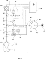
- Fig. 1 schematically shows the fluidic structure of the Blas Kunststoffzu operation a blow molding machine to a blow mold 12.
- a preform 10 is arranged, which is acted upon via a supply line 8 with a blown air.
- the blown air is passed from a blast air supply 40 to a blown air distributor 42, which distributes the blown air via the connection points 38 and supply lines 36 connected thereto to blowing stations each having a blow mold 12.
- the blown air distributor 42 may be a rotary distributor.
- the blow mold is communicatively connected to the Blas Kunststoffzu réelle 8.
- the Blas Kunststoffzu réelle 8 is connected in the present embodiment with the gas lines 2, 4 and 6. Via the gas line 2, the Blas Kunststoffzu effet 8 can be vented.
- the valve 28 is opened.
- the controller transmits a signal to the signal converter 30, which is mechanically and / or electrically coupled to the valve 28.
- the valve 28 is open, a pressure from the Blas Kunststoffzutechnisch 8 slides on the muffler 32 and there are delivered to the environment.
- the control of the valves 24 and 52 is analogous to the control of the valve 28 from.
- the valves 24, 28 and 52 can be actuated via a control air (not shown).
- the signal converters 26, 30 and 54 assigned to the valves 24, 28 and 52 can be provided as condition sensors which transmit the open position or the closed position of the valves to the controller 18.
- the gas line 4 is dominated by the shut-off valve 24.
- the check valve 24 is coupled to the signal converter 26. Via the gas line 4, a blown air can be passed to the preform 10 within the blow mold 12, which serves in particular for the finished blowing of the container to be formed.
- the finished blowing takes place in particular abruptly and with a high, rapidly applied gas pressure.
- a blowgas pressure of 40 bar can be provided for the finished blowing.
- the shut-off valve 24 may have an opening cross-section of about 300 mm 2 .
- the shut-off valve 24 is preferably connected directly to the distributor 42 on the input side, ie without a pressure reducer, throttles or the like. Thus, a blow pressure provided by the manifold 42 is forwarded directly to the blow mold 12 via the valve 24.
- the gas line 6 serves to introduce a blown air into the preform 10 during a pre-blowing phase.
- the blowing air is introduced into the preform 10 such that the material of the preform expands in the direction of the inner wall 14 of the blow mold 12 in a controlled manner.
- throttle valve 16 is used to adjust the volume flow of the blowing air during the Vorblasphase according to the invention designed as a throttle cross-sectional control valve.
- the throttle valve 16 is connected via a signal converter 22 to the controller 18.
- the signal converter 22 receives to adjust the throttle valve 16 signals from the controller 18. It may be preferably provided that the throttle valve 16 is communicatively connected to a throttle position sensor 20, wherein the throttle position sensor 20, the position of the Throttle valve 16 detected and transmitted to the controller 18.
- the throttle valve 16 is connected on the input side directly communicating with the manifold 42.
- the manifold 42 it is provided that in the connection between the manifold 42 and the throttle valve 16 no pressure-reducing components such as pressure reducer or the like are arranged.
- the Fig. 1 shows a pre-blowing in the Vorblasphase with stepless throttle control or regulation. It can be clearly seen in relation to the state of the art in Fig. 4 in that a pressure regulating valve 48 in the pre-blowing circuit is dispensed with. By applying the method according to the invention can be dispensed with a down-regulation of the main blowing pressure, for example, to 10 bar.
- the pre-blowing pressure is taken directly from the Fertigblastik or from the manifold 42.
- the distributor 42 receives the blowing gas from the gas source 40.
- the throttle valve 16 is designed as an electromechanical actuator, which is addressed by the controller 18.
- the throttle valve 16 is via the throttle position sensor 20 information to the controller 18, in which the throttle setting is shown. This can be particularly helpful, for example, when the controller 18 sets a specific throttle value, the throttle valve 16 itself, however, does not reach the setting value. In this case, the throttle position sensor 20 will report a different throttle position to the controller 18 and, in addition, the controller 18 may generate an error message. Regardless of the specific embodiment, the controller 18 may thus be set up to generate an error message for displaying a faulty throttle valve 16 and / or forward it to the display.
- a throttle position sensor 20 is not absolutely necessary. It is envisaged that once a setting profile for the throttle valve 16 is deposited in the controller 18, which is traversed at each pre-blowing. Feedback by the sensor 20, however, aids in error analysis, e.g. when finished blown containers from a particular blowing station have defects that were generated during pre-blowing. The throttle valve 16 of this blow station can be selectively checked. This reduces downtime of the blow molding machine.
- the final blowing of the container follows. For a blown air from the manifold 42 via the valve 24 through the gas line 4 to the Blas Kunststoffzu arrangement 8 and thus passed to the blast air 12.
- the material of the preform guided to the wall of the blow mold after the pre-blowing be suddenly, ie particularly quickly, pressed further against the wall of the blow mold with high pressure. This ensures a good training of the bottle contour and for a quick cooling of the finished blown bottle.
- valve 24 and the associated finished blower circuit be dispensed with, specifically when the throttle valve 16 permits a sudden opening and thus a sudden delivery of the finished blown air into the preform.
- the throttle valve 16 would have to open to an opening cross-section of about 300 mm 2 and also the throttle valve 16 would have a fast reaction time.
- a pressure transducer is shown, which detects the gas pressure in the blast air supply line 8 and provides a gas pressure descriptive information for transmission to the controller 18.
- the gas pressure of the blown gas introduced into the preform can thus be monitored by the controller 18 and further processed for control purposes.
- a control of the valves 16, 24 and / or 28 can be coordinated on the basis of the blowing gas pressure.
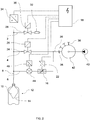
- Fig. 2 schematically shows the flow-mechanical structure of the Blas Kunststoffzu entry from a Blas Kunststoffers 40 via a Blas Kunststoffverteiler 42 to the blow mold 12 in a further embodiment.
- a flow sensor 44 is provided in the Vorblasnik, ie in the region of the gas line 6 between the Blas Kunststoffzu arrangement 8 and the manifold 42.
- the volume flow sensor is in particular arranged downstream downstream of the throttle valve 16. Furthermore, it is missing Fig. 1 a throttle position sensor 20.
- the volume flow sensor 44 measures the volume flow of the blown air through the gas line 6 and passes this information via a signal converter 30 to the controller 18.
- the information of the volume flow sensor 44 are used for a control algorithm which is executed by the controller 18.
- the volume flow through the gas line 6 can be provided as a control variable.
- the volumetric flow sensor 44 can also be arranged upstream of the throttle valve 16.
- Throttle valve 16 guided flow with knowledge of the differential pressure between the input and output of the throttle valve 16 and the throttle valve position can be calculated by the controller 18.
- the measured variable of the volume flow sensor 32 directly influences the setting of the throttle valve 16.
- the direct influence can be provided if the controller 18 recognizes from the measured values of the volume flow sensor 44 that the blown air volume introduced into the preform 10 exceeds or falls below the corridor limits defined for this purpose.
- a direct coupling of the measured value of the volume flow sensor 32 to the setting of the throttle valve 16 may be provided by way of a closed loop.
- a volumetric flow sensor 44 also has the advantage that aging states or malfunctioning of a throttle valve 16 of a blowing station can be detected.
- Fig. 3 schematically shows the Blas Kunststoffzu entry a blow molding machine to the blow mold 12, in which a stepped throttle valve 36 in Vorblas Vietnamese, ie in the region of the gas line 6 between the manifold 42 and the Blas Kunststoffzu entry 8, is arranged.
- a stage setting of the blast air supply to the preform 10 within the blow mold 12 during the pre-blowing is provided. This can be advantageous if a stepless and thus finely adjustable adjustment of a throttle is not necessary for the process of pre-blowing.
- a stepped throttle valve 36 is simpler as a continuously variable throttle valve 16 from the Fig. 1 and 2 ,
- the throttle valve 36 is cheaper and less complex mechanically. It is readily conceivable that the stepped throttle valve 36 with a throttle adjustment sensor 20 from Fig. 1 and / or a volumetric flow sensor 32 Fig. 2 combined.
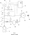
- Fig. 4 shows purely schematically a known from the prior art fluid mechanical structure of a Blas Kunststoffzu entry from a Blas Kunststoffers 40 via a manifold 42 to a blow mold 12 a blowing station of the blow molding machine.
- a manually adjustable throttle valve 16 for flow control of Vorblas Kunststoff provided. Upstream of the throttle valve 56, a blow line 52 controlling the gas line 6 is arranged, which is controllable via the signal converter 54 by means of the controller 18.
- a container 50 is connected to the gas line 6, which is designed as a gas buffer and allows a distribution of the blowing air to other blowing stations of the blow molding machine.
- a pressure control valve 48 is provided, which is acted on the input side with the main blowing pressure from the manifold 42.
- the pressure control valve 48 reduces the pressure of the blown air from the manifold 42 to about 10 bar.
- the pressure regulating valve is communicatively connected to the container 50. If necessary, the container 50 distributes the blown air to a plurality of blowing stations of a blow molding machine.
- a disadvantage of the blast air according to. Fig. 4 is the use of an expensive and maintenance-intensive pressure regulator 48 and a container 50, which takes over the distribution of Vorblas Kunststoff on the individual blowing stations of a blow molding machine.
- the Vorblasnik is so complex and error prone.
- the pressure of the Vorblas Kunststoff can be adjusted only centrally on the pressure control valve 48 for all blow molding stations of a blow molding machine.
Landscapes
- Engineering & Computer Science (AREA)
- Manufacturing & Machinery (AREA)
- Mechanical Engineering (AREA)
- Blow-Moulding Or Thermoforming Of Plastics Or The Like (AREA)
Claims (15)
- Procédé de commande d'une machine de moulage par soufflage pour la production de récipients en matériau thermoplastique, un gaz de soufflage pour le moulage par soufflage du récipient étant introduit dans une préforme (10) thermiquement conditionnée pendant que cette préforme (10) est maintenue dans un moule de soufflage (12) de la machine de moulage par soufflage,
le gaz de soufflage étant, au cours d'une phase de pré-soufflage, introduit dans la préforme (10) de façon telle que le matériau thermiquement conditionné de la préforme (10) s'approche de la paroi du moule de soufflage (12),
le gaz de soufflage étant, au cours d'une phase de finition suivante, introduit dans la préforme (10) de façon telle que le matériau thermiquement conditionné de la préforme (10) soit pressé dans les contours de la paroi (14) du moule de soufflage (12), et
le débit volumétrique du gaz de soufflage étant, au moins pendant la phase de pré-soufflage, fixé par une soupape d'étranglement (16) réglable,
caractérisé en ce que
l'on utilise comme soupape d'étranglement (16) une soupape pouvant être commandée au moyen d'une unité de commande (18), et en ce qu'une unité de commande (18) génère un signal de commande pour le réglage de la soupape d'étranglement (16) et que la soupape d'étranglement (16) est réglée en fonction du signal de commande. - Procédé selon la revendication 1, caractérisé en ce que la soupape d'étranglement (16) utilisée est une soupape d'étranglement pouvant être actionnée électriquement.
- Procédé selon l'une des revendications 1 ou 2, caractérisé en ce qu'une soupape d'étranglement (16) réglable en continu ou une soupape d'étranglement (16) réglable par paliers est utilisée.
- Procédé selon l'une des revendications précédentes, caractérisé en ce que la pression du côté entrée de la soupape d'étranglement (16) est celle du gaz de soufflage de la phase de finition.
- Procédé selon l'une des revendications précédentes, caractérisé en ce qu'un capteur de position (20) de l'étranglement saisit le réglage de la soupape d'étranglement (16) et génère un signal de position qui contient une information sur la position de la soupape d'étranglement (16) et que le signal de position est transmis à l'unité de commande (18), en quoi il est notamment prévu que l'unité de commande (18) génère le signal de commande pour le réglage de la soupape d'étranglement (16) en fonction du signal de position.
- Procédé selon l'une des revendications précédentes, caractérisé en ce que la soupape d'étranglement utilisée a une section d'ouverture allant de 0,8 mm2 à 20 mm2 compris.
- Procédé selon l'une des revendications précédentes, caractérisé en ce qu'un profil de consigne est stocké dans l'unité de commande (18), lequel décrit la variation dans le temps du débit volumétrique du gaz de soufflage et que l'unité de commande (18) génère le signal de commande pour le réglage de la soupape d'étranglement (16) en fonction du profil de consigne.
- Procédé selon l'une des revendications précédentes, caractérisé en ce qu'un capteur (32) de débit volumétrique raccordé de façon communicante à la soupape d'étranglement (16) génère un signal de débit volumétrique avec un information sur la quantité débitée de gaz de soufflage, le signal de débit volumétrique étant transmis à l'unité de commande (18).
- Procédé selon la revendication 8, caractérisé en ce qu'une valeur limite supérieure et/ou inférieure souhaitée pour le débit volumétrique du gaz de soufflage est stockée dans l'unité de commande (18) pour un moment au moins de la phase de pré-soufflage, l'unité de commande (18) comparant le signal de débit volumétrique avec les valeurs limites et générant le signal de commande en fonction de la différence entre le signal de débit volumétrique et l'une au moins des valeurs limites.
- Procédé selon l'une des revendications précédentes, caractérisé en ce que la soupape d'étranglement utilisée est une soupape munie d'un corps d'obturation pouvant être déplacé, notamment de façon magnétique, entre une position ouverte et une position fermée.
- Procédé selon la revendication 10, caractérisé en ce que le corps d'obturation de la soupape d'étranglement est déplacé avec une fréquence réglable en va-et-vient entre la position ouverte et la position fermée.
- Machine de moulage par soufflage pour la production de récipients en matériau thermoplastique, la machine de moulage par soufflage étant aménagée de façon telle qu'un gaz de soufflage pour le moulage par soufflage du récipient est introduit dans une préforme (10) thermiquement conditionnée pendant que cette préforme (10) est maintenue dans un moule de soufflage (12) de la machine de moulage par soufflage,
le gaz de soufflage étant, au cours d'une phase de pré-soufflage, introduit dans la préforme (10) de façon telle que le matériau thermiquement conditionné de la préforme (10) s'approche de la paroi du moule de soufflage (12),
le gaz de soufflage étant, au cours d'une phase de finition suivante, introduit dans la préforme (10) de façon telle que le matériau thermiquement conditionné de la préforme (10) soit pressé dans les contours de la paroi (14) du moule de soufflage (12), et
le débit volumétrique du gaz de soufflage étant, au moins pendant la phase de pré-soufflage, fixé par une soupape d'étranglement (16) réglable,
caractérisé en ce que
est prévue en guise de soupape d'étranglement (16) une soupape d'étranglement pouvant être commandée au moyen d'une unité de commande (18), la machine de moulage par soufflage étant aménagée de façon telle que l'unité de commande (18) génère un signal de commande pour le réglage de la soupape d'étranglement (16) et que la soupape d'étranglement (16) est réglée en fonction du signal de commande. - Machine de moulage par soufflage selon la revendication 12, caractérisée en ce qu'un dispositif de commande est prévu pour la commande de la machine, lequel dispositif comporte une unité de commande (18) conçue de façon à générer un signal de commande pour le réglage d'une soupape d'étranglement (16) qui commande le débit volumétrique du gaz de soufflage, l'unité de commande (18) étant notamment prévue pour générer le signal de commande de la soupape d'étranglement (16) en fonction d'un signal de position qui représente la position de l'étranglement de la soupape d'étranglement (16).
- Machine de moulage par soufflage selon la revendication 12 ou 13, caractérisée en ce qu'un profil de consigne est stocké dans l'unité de commande (18), lequel décrit la variation dans le temps du débit volumétrique du gaz de soufflage et que l'unité de commande (18) est conçue pour générer le signal de commande pour le réglage de la soupape d'étranglement (16) en fonction du profil de consigne.
- Machine de moulage par soufflage selon l'une des revendications 12 à 14, caractérisée en ce qu'une valeur limite supérieure et/ou inférieure souhaitée pour le débit volumétrique du gaz de soufflage est stockée dans l'unité de commande (18) pour un moment au moins du moulage par soufflage, l'unité de commande (18) étant conçue pour comparer un signal de débit volumétrique comportant une information sur la quantité de gaz de soufflage introduit dans la préforme (10) avec les valeurs limites et déterminer une différence entre le débit volumétrique et les valeurs limites.
Applications Claiming Priority (1)
| Application Number | Priority Date | Filing Date | Title |
|---|---|---|---|
| DE102014010861.9A DE102014010861A1 (de) | 2014-07-25 | 2014-07-25 | Volumengesteuerte Blasluftzuführung |
Publications (3)
| Publication Number | Publication Date |
|---|---|
| EP2977184A1 EP2977184A1 (fr) | 2016-01-27 |
| EP2977184B1 true EP2977184B1 (fr) | 2019-09-04 |
| EP2977184B2 EP2977184B2 (fr) | 2023-02-22 |
Family
ID=53793906
Family Applications (1)
| Application Number | Title | Priority Date | Filing Date |
|---|---|---|---|
| EP15002111.1A Active EP2977184B2 (fr) | 2014-07-25 | 2015-07-16 | Entree d'air de soufflage a commande de volume |
Country Status (4)
| Country | Link |
|---|---|
| US (2) | US10112337B2 (fr) |
| EP (1) | EP2977184B2 (fr) |
| CN (1) | CN105415648B (fr) |
| DE (1) | DE102014010861A1 (fr) |
Cited By (2)
| Publication number | Priority date | Publication date | Assignee | Title |
|---|---|---|---|---|
| EP3970946A3 (fr) * | 2020-09-17 | 2022-07-06 | Norgren AG | Dispositif de commande d'écoulement de fluide |
| EP4302963A1 (fr) | 2022-07-04 | 2024-01-10 | Eugen Seitz AG | Unité d'accélérateur |
Families Citing this family (10)
| Publication number | Priority date | Publication date | Assignee | Title |
|---|---|---|---|---|
| DE102016013635B4 (de) * | 2016-11-16 | 2021-08-05 | Aventics Gmbh | Vorrichtung und Verfahren zur Steuerung des Blasfluiddurchflusses beim Blasformen von Behältern |
| DE102017120863A1 (de) * | 2017-09-10 | 2019-03-14 | Khs Corpoplast Gmbh | Verfahren und Vorrichtung zur Herstellung von Behältern aus thermoplastischem Material |
| FR3071745B1 (fr) * | 2017-09-29 | 2022-07-22 | Fives Machining | Dispositif de dosage d'une ou plusieurs poudre(s), imprimante 3d correspondante et procede de dosage |
| DE102020212739A1 (de) | 2020-10-08 | 2022-04-14 | Festo Se & Co. Kg | Verfahren zum Betreiben einer Fluidsteuereinheit, Fluidsteuereinheit und Streckblasmaschine |
| DE102021115026A1 (de) | 2021-06-10 | 2022-12-15 | Khs Gmbh | Vorrichtung zum Herstellen von Behältern aus thermisch konditionierten Vorformlingen aus thermoplastischem Material |
| DE102021120750A1 (de) | 2021-08-10 | 2023-02-16 | Krones Aktiengesellschaft | Blasmaschine mit Druckansteuerung während des Blasprozesses |
| DE102021128205A1 (de) | 2021-10-28 | 2023-05-04 | Krones Aktiengesellschaft | Vorrichtung und Verfahren zum Umformen von Kunststoffvorformlingen zu Kunststoffbehältnissen mit verstellbarer Drossel |
| CN115091725B (zh) * | 2022-07-04 | 2023-05-05 | 浙江同发塑机有限公司 | 用于生产农药包装桶的智能吹塑机及其控制方法 |
| DE102023101832A1 (de) * | 2023-01-25 | 2024-07-25 | Krones Aktiengesellschaft | Vorrichtung und Verfahren zum Umformen von Kunststoffvorformlingen zu Kunststoffbehältnissen mit automatisierter Drosselverstellung |
| DE102024128297A1 (de) | 2024-09-30 | 2026-04-02 | Khs Gmbh | Vorrichtung und Verfahren zur umformenden Herstellung von Behältern mit aktiv temperierten äußeren Formen |
Citations (20)
| Publication number | Priority date | Publication date | Assignee | Title |
|---|---|---|---|---|
| US20030209266A1 (en) | 2002-04-19 | 2003-11-13 | Alain Dupuis | Device for regulating the flow rate and/or the pressure of a fluid |
| DE202004015982U1 (de) | 2004-10-14 | 2004-12-16 | Liebau, Lothar, Dipl.-Ing. | Drosseleinrichtung für Abwasserkanäle |
| DE202004018237U1 (de) | 2004-11-25 | 2005-02-24 | Festo Ag & Co. | Ventilanordnung |
| US20060012085A1 (en) | 2004-07-14 | 2006-01-19 | Danny De Bruyn | Method for blowing objects |
| US20060110483A1 (en) | 2002-03-18 | 2006-05-25 | Volker Damerow | Device for the production of plastic containers by means of stretch blow moulding and device for coating the inner walls of a plastic container |
| DE102005035878B3 (de) | 2005-07-30 | 2006-08-31 | Deutsches Zentrum für Luft- und Raumfahrt e.V. | Magnetisch betätigbares Ventil |
| DE102006007157A1 (de) | 2005-07-20 | 2007-01-25 | Continental Teves Ag & Co. Ohg | Elektrisch ansteuerbares Ventil |
| DE102004019152B4 (de) | 2004-04-21 | 2007-05-31 | Robert Bosch Gmbh | Verfahren zum Betreiben eines Magnetventils zur Mengensteuerung |
| US20090102082A1 (en) | 2004-11-19 | 2009-04-23 | Andre Gattolliat | Self-Controlled Solenoid Valve Device |
| US20100201013A1 (en) | 2006-12-05 | 2010-08-12 | Sidel Participations | Method for producing a vessel from a preform, with feedback depending on the development point of the preform |
| US20100276849A1 (en) | 2007-09-24 | 2010-11-04 | Sidel Participations | Method for making containers comprising an intermediate depressuring operation |
| EP2091715B1 (fr) | 2006-12-22 | 2011-07-20 | Krones AG | Procédé de fabrication de récipients |
| EP2250413B1 (fr) | 2008-03-03 | 2011-08-31 | Sidel Participations | Installation de soufflage de recipients thermoplastiques equipee d'un composant pneumatique formant electrovanne et incorporant un reglage de debit |
| WO2012139717A1 (fr) | 2011-04-12 | 2012-10-18 | Thomas Magnete Gmbh | Soupape de limitation de pression commutable |
| EP2423543B1 (fr) | 2010-08-24 | 2013-03-06 | Robert Bosch GmbH | Vanne de fluides à soufflage pour dispositif de moulage par soufflage, dispositif de moulage par soufflage et procédé de moulage par soufflage |
| US20130187304A1 (en) | 2010-09-16 | 2013-07-25 | Sidel Participations | Method for manufacturing a container from a preform, with feedback depending on a minimum pressure detected |
| WO2013135838A1 (fr) | 2012-03-14 | 2013-09-19 | Norgren Gmbh | Système de moulage par injection-soufflage avec étirage doté d'une soupape de pré-soufflage proportionnelle |
| EP2669069A1 (fr) | 2012-05-31 | 2013-12-04 | Robert Bosch GmbH | Vanne de fluides à soufflage, unité de moulage par soufflage et procédé de moulage par soufflage |
| WO2014068080A1 (fr) | 2012-11-01 | 2014-05-08 | Norgren Gmbh | Système de moulage par soufflage avec étirage comprenant actionnement simultané de valve de présoufflage |
| DE102013111950A1 (de) | 2013-10-30 | 2015-04-30 | Krones Ag | Umformvorrichtung zum Umformen von Kunststoffvorformlingen zu Kunststoffbehältnissen |
Family Cites Families (7)
| Publication number | Priority date | Publication date | Assignee | Title |
|---|---|---|---|---|
| DE2742693C2 (de) * | 1977-09-22 | 1983-08-11 | Gildemeister Corpoplast Gmbh, 2000 Hamburg | Maschine zum Blasformen von Hohlkörpern, insbesondere von Flaschen, aus thermoplastischem Kunststoff |
| DE4340291A1 (de) * | 1993-11-26 | 1995-06-01 | Krupp Corpoplast Masch | Mehrfachnutzung von Blasluft |
| AT407856B (de) * | 1997-07-07 | 2001-07-25 | Hygrama Ag | Verfahren und vorrichtung zur herstellung von hohlen kunststoffbehältern |
| FR2848906B1 (fr) * | 2002-12-23 | 2006-08-18 | Sidel Sa | Procede et installation de fabrication d'un recipient en matiere plastique |
| FR2962930B1 (fr) * | 2010-07-20 | 2012-08-31 | Sidel Participations | Procede de formage d'un recipient par soufflage et remplissage |
| DE202011103680U1 (de) | 2011-07-25 | 2011-12-16 | Lycka Solution Gmbh | 3-D-Inlay für Handyschalen |
| DE102011110962A1 (de) * | 2011-08-18 | 2013-02-21 | Khs Corpoplast Gmbh | Verfahren und Vorrichtung zur Blasformung von Behältern |
-
2014
- 2014-07-25 DE DE102014010861.9A patent/DE102014010861A1/de not_active Withdrawn
-
2015
- 2015-07-16 EP EP15002111.1A patent/EP2977184B2/fr active Active
- 2015-07-23 CN CN201510681297.7A patent/CN105415648B/zh active Active
- 2015-07-24 US US14/808,686 patent/US10112337B2/en active Active
-
2018
- 2018-09-28 US US16/145,413 patent/US10857717B2/en active Active
Patent Citations (20)
| Publication number | Priority date | Publication date | Assignee | Title |
|---|---|---|---|---|
| US20060110483A1 (en) | 2002-03-18 | 2006-05-25 | Volker Damerow | Device for the production of plastic containers by means of stretch blow moulding and device for coating the inner walls of a plastic container |
| US20030209266A1 (en) | 2002-04-19 | 2003-11-13 | Alain Dupuis | Device for regulating the flow rate and/or the pressure of a fluid |
| DE102004019152B4 (de) | 2004-04-21 | 2007-05-31 | Robert Bosch Gmbh | Verfahren zum Betreiben eines Magnetventils zur Mengensteuerung |
| US20060012085A1 (en) | 2004-07-14 | 2006-01-19 | Danny De Bruyn | Method for blowing objects |
| DE202004015982U1 (de) | 2004-10-14 | 2004-12-16 | Liebau, Lothar, Dipl.-Ing. | Drosseleinrichtung für Abwasserkanäle |
| US20090102082A1 (en) | 2004-11-19 | 2009-04-23 | Andre Gattolliat | Self-Controlled Solenoid Valve Device |
| DE202004018237U1 (de) | 2004-11-25 | 2005-02-24 | Festo Ag & Co. | Ventilanordnung |
| DE102006007157A1 (de) | 2005-07-20 | 2007-01-25 | Continental Teves Ag & Co. Ohg | Elektrisch ansteuerbares Ventil |
| DE102005035878B3 (de) | 2005-07-30 | 2006-08-31 | Deutsches Zentrum für Luft- und Raumfahrt e.V. | Magnetisch betätigbares Ventil |
| US20100201013A1 (en) | 2006-12-05 | 2010-08-12 | Sidel Participations | Method for producing a vessel from a preform, with feedback depending on the development point of the preform |
| EP2091715B1 (fr) | 2006-12-22 | 2011-07-20 | Krones AG | Procédé de fabrication de récipients |
| US20100276849A1 (en) | 2007-09-24 | 2010-11-04 | Sidel Participations | Method for making containers comprising an intermediate depressuring operation |
| EP2250413B1 (fr) | 2008-03-03 | 2011-08-31 | Sidel Participations | Installation de soufflage de recipients thermoplastiques equipee d'un composant pneumatique formant electrovanne et incorporant un reglage de debit |
| EP2423543B1 (fr) | 2010-08-24 | 2013-03-06 | Robert Bosch GmbH | Vanne de fluides à soufflage pour dispositif de moulage par soufflage, dispositif de moulage par soufflage et procédé de moulage par soufflage |
| US20130187304A1 (en) | 2010-09-16 | 2013-07-25 | Sidel Participations | Method for manufacturing a container from a preform, with feedback depending on a minimum pressure detected |
| WO2012139717A1 (fr) | 2011-04-12 | 2012-10-18 | Thomas Magnete Gmbh | Soupape de limitation de pression commutable |
| WO2013135838A1 (fr) | 2012-03-14 | 2013-09-19 | Norgren Gmbh | Système de moulage par injection-soufflage avec étirage doté d'une soupape de pré-soufflage proportionnelle |
| EP2669069A1 (fr) | 2012-05-31 | 2013-12-04 | Robert Bosch GmbH | Vanne de fluides à soufflage, unité de moulage par soufflage et procédé de moulage par soufflage |
| WO2014068080A1 (fr) | 2012-11-01 | 2014-05-08 | Norgren Gmbh | Système de moulage par soufflage avec étirage comprenant actionnement simultané de valve de présoufflage |
| DE102013111950A1 (de) | 2013-10-30 | 2015-04-30 | Krones Ag | Umformvorrichtung zum Umformen von Kunststoffvorformlingen zu Kunststoffbehältnissen |
Non-Patent Citations (1)
| Title |
|---|
| F . SASS ET AL., DUBBELS TASCHENBUCH FÜR DEN MASCHINENBAU, 1963, Berlin, pages 233 |
Cited By (2)
| Publication number | Priority date | Publication date | Assignee | Title |
|---|---|---|---|---|
| EP3970946A3 (fr) * | 2020-09-17 | 2022-07-06 | Norgren AG | Dispositif de commande d'écoulement de fluide |
| EP4302963A1 (fr) | 2022-07-04 | 2024-01-10 | Eugen Seitz AG | Unité d'accélérateur |
Also Published As
| Publication number | Publication date |
|---|---|
| EP2977184A1 (fr) | 2016-01-27 |
| DE102014010861A1 (de) | 2016-01-28 |
| US20190030778A1 (en) | 2019-01-31 |
| CN105415648B (zh) | 2019-07-09 |
| US10857717B2 (en) | 2020-12-08 |
| US10112337B2 (en) | 2018-10-30 |
| US20160023396A1 (en) | 2016-01-28 |
| CN105415648A (zh) | 2016-03-23 |
| EP2977184B2 (fr) | 2023-02-22 |
Similar Documents
| Publication | Publication Date | Title |
|---|---|---|
| EP2977184B1 (fr) | Entree d'air de soufflage a commande de volume | |
| EP2470348B1 (fr) | Procédé et dispositif de moulage par soufflage de contenants | |
| EP2436507B2 (fr) | Dispositif et procédé de déformation d'ébauches en plastique en conteneurs en plastique dotés d'une capacité d'expulsion variable | |
| EP3015248B1 (fr) | Procede et dispositif de transformations d'ebauches en plastique avec modification de coupe transversale d'un debit volumetrique | |
| EP4155055B1 (fr) | Dispositif et procédé de formage des préformes en matière plastique pourvu de dispositif soupape commandée | |
| EP2091715B1 (fr) | Procédé de fabrication de récipients | |
| EP4173797B1 (fr) | Dispositif et procédé de formage d'ébauches en plastique en récipients en plastique dotés d'un étranglement réglable | |
| EP3645238B1 (fr) | Dispositif et procédé de compensation du temps de commutation sur un bloc de soupapes | |
| EP3804958A1 (fr) | Procédé de fonctionnement d'une installation de traitement des récipients et installation de traitement des récipients au moyen de paramètres optimisés | |
| EP4241961A2 (fr) | Surveillance de l'usure d'une soupape | |
| DE102012013840A1 (de) | Verfahren und Vorrichtung zur Blas- und Kühlluftregelung einer l.S. Glasformmaschine | |
| EP3941711B1 (fr) | Dispositif de soupape de soufflage pour un dispositif de soufflage | |
| EP3711926B1 (fr) | Dispositif de soupape de soufflage pour un dispositif de soufflage | |
| EP3580035B1 (fr) | Dispositif et procédé pour transformer des préformes en matière plastique en bouteilles en matière plastique comprenant une partie fond mobile | |
| EP4134222A1 (fr) | Machine à souffler à commande de pression lors du processus de soufflage | |
| DE102017120861A1 (de) | Verfahren und Vorrichtung zur Herstellung von Behältern aus thermoplastischem Material | |
| DE102008030866A1 (de) | Blasvorrichtung, insbesondere für Behältnisse | |
| EP3374674B1 (fr) | Dispositif de formage et de remplissage simultanés de récipients à partir de préformes, système de soupape et utilisation dudit système de soupape dans un procédé de formage et de remplissage simultanés de récipients à partir de préformes | |
| EP4366930B1 (fr) | Dispositif d'extrusion et procédé de fabrication d'un objet présentant une cavité | |
| EP2853375B1 (fr) | Procédé de fonctionnement d'une machine de thermoformage et machine de thermoformage | |
| EP2230219A1 (fr) | Mécanisme de tête de moulage d'une machine de moulage de verre | |
| EP2230215A1 (fr) | Mécanisme de fond ébaucheur d'une machine de moulage de verre | |
| DE10357365A1 (de) | Druckgießvorrichtung und Verfahren zum Druckgießen mit einem definierten Forminnendruck | |
| EP2230218A1 (fr) | Mécanisme d'ouverture et de fermeture de moulage d'une machine de moulage de verre |
Legal Events
| Date | Code | Title | Description |
|---|---|---|---|
| PUAI | Public reference made under article 153(3) epc to a published international application that has entered the european phase |
Free format text: ORIGINAL CODE: 0009012 |
|
| AK | Designated contracting states |
Kind code of ref document: A1 Designated state(s): AL AT BE BG CH CY CZ DE DK EE ES FI FR GB GR HR HU IE IS IT LI LT LU LV MC MK MT NL NO PL PT RO RS SE SI SK SM TR |
|
| AX | Request for extension of the european patent |
Extension state: BA ME |
|
| 17P | Request for examination filed |
Effective date: 20160727 |
|
| RBV | Designated contracting states (corrected) |
Designated state(s): AL AT BE BG CH CY CZ DE DK EE ES FI FR GB GR HR HU IE IS IT LI LT LU LV MC MK MT NL NO PL PT RO RS SE SI SK SM TR |
|
| STAA | Information on the status of an ep patent application or granted ep patent |
Free format text: STATUS: EXAMINATION IS IN PROGRESS |
|
| 17Q | First examination report despatched |
Effective date: 20170822 |
|
| GRAP | Despatch of communication of intention to grant a patent |
Free format text: ORIGINAL CODE: EPIDOSNIGR1 |
|
| STAA | Information on the status of an ep patent application or granted ep patent |
Free format text: STATUS: GRANT OF PATENT IS INTENDED |
|
| INTG | Intention to grant announced |
Effective date: 20190405 |
|
| GRAS | Grant fee paid |
Free format text: ORIGINAL CODE: EPIDOSNIGR3 |
|
| GRAA | (expected) grant |
Free format text: ORIGINAL CODE: 0009210 |
|
| STAA | Information on the status of an ep patent application or granted ep patent |
Free format text: STATUS: THE PATENT HAS BEEN GRANTED |
|
| AK | Designated contracting states |
Kind code of ref document: B1 Designated state(s): AL AT BE BG CH CY CZ DE DK EE ES FI FR GB GR HR HU IE IS IT LI LT LU LV MC MK MT NL NO PL PT RO RS SE SI SK SM TR |
|
| REG | Reference to a national code |
Ref country code: GB Ref legal event code: FG4D Free format text: NOT ENGLISH |
|
| REG | Reference to a national code |
Ref country code: CH Ref legal event code: EP |
|
| REG | Reference to a national code |
Ref country code: AT Ref legal event code: REF Ref document number: 1174757 Country of ref document: AT Kind code of ref document: T Effective date: 20190915 |
|
| REG | Reference to a national code |
Ref country code: DE Ref legal event code: R096 Ref document number: 502015010198 Country of ref document: DE |
|
| REG | Reference to a national code |
Ref country code: IE Ref legal event code: FG4D Free format text: LANGUAGE OF EP DOCUMENT: GERMAN |
|
| REG | Reference to a national code |
Ref country code: CH Ref legal event code: NV Representative=s name: R.A. EGLI AND CO, PATENTANWAELTE, CH |
|
| REG | Reference to a national code |
Ref country code: NL Ref legal event code: MP Effective date: 20190904 |
|
| REG | Reference to a national code |
Ref country code: LT Ref legal event code: MG4D |
|
| PG25 | Lapsed in a contracting state [announced via postgrant information from national office to epo] |
Ref country code: SE Free format text: LAPSE BECAUSE OF FAILURE TO SUBMIT A TRANSLATION OF THE DESCRIPTION OR TO PAY THE FEE WITHIN THE PRESCRIBED TIME-LIMIT Effective date: 20190904 Ref country code: BG Free format text: LAPSE BECAUSE OF FAILURE TO SUBMIT A TRANSLATION OF THE DESCRIPTION OR TO PAY THE FEE WITHIN THE PRESCRIBED TIME-LIMIT Effective date: 20191204 Ref country code: LT Free format text: LAPSE BECAUSE OF FAILURE TO SUBMIT A TRANSLATION OF THE DESCRIPTION OR TO PAY THE FEE WITHIN THE PRESCRIBED TIME-LIMIT Effective date: 20190904 Ref country code: HR Free format text: LAPSE BECAUSE OF FAILURE TO SUBMIT A TRANSLATION OF THE DESCRIPTION OR TO PAY THE FEE WITHIN THE PRESCRIBED TIME-LIMIT Effective date: 20190904 Ref country code: FI Free format text: LAPSE BECAUSE OF FAILURE TO SUBMIT A TRANSLATION OF THE DESCRIPTION OR TO PAY THE FEE WITHIN THE PRESCRIBED TIME-LIMIT Effective date: 20190904 Ref country code: NO Free format text: LAPSE BECAUSE OF FAILURE TO SUBMIT A TRANSLATION OF THE DESCRIPTION OR TO PAY THE FEE WITHIN THE PRESCRIBED TIME-LIMIT Effective date: 20191204 |
|
| PG25 | Lapsed in a contracting state [announced via postgrant information from national office to epo] |
Ref country code: LV Free format text: LAPSE BECAUSE OF FAILURE TO SUBMIT A TRANSLATION OF THE DESCRIPTION OR TO PAY THE FEE WITHIN THE PRESCRIBED TIME-LIMIT Effective date: 20190904 Ref country code: GR Free format text: LAPSE BECAUSE OF FAILURE TO SUBMIT A TRANSLATION OF THE DESCRIPTION OR TO PAY THE FEE WITHIN THE PRESCRIBED TIME-LIMIT Effective date: 20191205 Ref country code: ES Free format text: LAPSE BECAUSE OF FAILURE TO SUBMIT A TRANSLATION OF THE DESCRIPTION OR TO PAY THE FEE WITHIN THE PRESCRIBED TIME-LIMIT Effective date: 20190904 Ref country code: RS Free format text: LAPSE BECAUSE OF FAILURE TO SUBMIT A TRANSLATION OF THE DESCRIPTION OR TO PAY THE FEE WITHIN THE PRESCRIBED TIME-LIMIT Effective date: 20190904 Ref country code: AL Free format text: LAPSE BECAUSE OF FAILURE TO SUBMIT A TRANSLATION OF THE DESCRIPTION OR TO PAY THE FEE WITHIN THE PRESCRIBED TIME-LIMIT Effective date: 20190904 |
|
| PG25 | Lapsed in a contracting state [announced via postgrant information from national office to epo] |
Ref country code: PT Free format text: LAPSE BECAUSE OF FAILURE TO SUBMIT A TRANSLATION OF THE DESCRIPTION OR TO PAY THE FEE WITHIN THE PRESCRIBED TIME-LIMIT Effective date: 20200106 Ref country code: NL Free format text: LAPSE BECAUSE OF FAILURE TO SUBMIT A TRANSLATION OF THE DESCRIPTION OR TO PAY THE FEE WITHIN THE PRESCRIBED TIME-LIMIT Effective date: 20190904 Ref country code: EE Free format text: LAPSE BECAUSE OF FAILURE TO SUBMIT A TRANSLATION OF THE DESCRIPTION OR TO PAY THE FEE WITHIN THE PRESCRIBED TIME-LIMIT Effective date: 20190904 Ref country code: RO Free format text: LAPSE BECAUSE OF FAILURE TO SUBMIT A TRANSLATION OF THE DESCRIPTION OR TO PAY THE FEE WITHIN THE PRESCRIBED TIME-LIMIT Effective date: 20190904 Ref country code: PL Free format text: LAPSE BECAUSE OF FAILURE TO SUBMIT A TRANSLATION OF THE DESCRIPTION OR TO PAY THE FEE WITHIN THE PRESCRIBED TIME-LIMIT Effective date: 20190904 |
|
| PG25 | Lapsed in a contracting state [announced via postgrant information from national office to epo] |
Ref country code: IS Free format text: LAPSE BECAUSE OF FAILURE TO SUBMIT A TRANSLATION OF THE DESCRIPTION OR TO PAY THE FEE WITHIN THE PRESCRIBED TIME-LIMIT Effective date: 20200224 Ref country code: SM Free format text: LAPSE BECAUSE OF FAILURE TO SUBMIT A TRANSLATION OF THE DESCRIPTION OR TO PAY THE FEE WITHIN THE PRESCRIBED TIME-LIMIT Effective date: 20190904 Ref country code: SK Free format text: LAPSE BECAUSE OF FAILURE TO SUBMIT A TRANSLATION OF THE DESCRIPTION OR TO PAY THE FEE WITHIN THE PRESCRIBED TIME-LIMIT Effective date: 20190904 Ref country code: CZ Free format text: LAPSE BECAUSE OF FAILURE TO SUBMIT A TRANSLATION OF THE DESCRIPTION OR TO PAY THE FEE WITHIN THE PRESCRIBED TIME-LIMIT Effective date: 20190904 |
|
| REG | Reference to a national code |
Ref country code: DE Ref legal event code: R026 Ref document number: 502015010198 Country of ref document: DE |
|
| PLBI | Opposition filed |
Free format text: ORIGINAL CODE: 0009260 |
|
| PLAX | Notice of opposition and request to file observation + time limit sent |
Free format text: ORIGINAL CODE: EPIDOSNOBS2 |
|
| 26 | Opposition filed |
Opponent name: KRONES AG Effective date: 20200604 Opponent name: SIDEL PARTICIPATIONS S.A.S. Effective date: 20200604 |
|
| PG2D | Information on lapse in contracting state deleted |
Ref country code: IS |
|
| PG25 | Lapsed in a contracting state [announced via postgrant information from national office to epo] |
Ref country code: DK Free format text: LAPSE BECAUSE OF FAILURE TO SUBMIT A TRANSLATION OF THE DESCRIPTION OR TO PAY THE FEE WITHIN THE PRESCRIBED TIME-LIMIT Effective date: 20190904 Ref country code: IS Free format text: LAPSE BECAUSE OF FAILURE TO SUBMIT A TRANSLATION OF THE DESCRIPTION OR TO PAY THE FEE WITHIN THE PRESCRIBED TIME-LIMIT Effective date: 20200105 |
|
| PG25 | Lapsed in a contracting state [announced via postgrant information from national office to epo] |
Ref country code: SI Free format text: LAPSE BECAUSE OF FAILURE TO SUBMIT A TRANSLATION OF THE DESCRIPTION OR TO PAY THE FEE WITHIN THE PRESCRIBED TIME-LIMIT Effective date: 20190904 |
|
| PLAF | Information modified related to communication of a notice of opposition and request to file observations + time limit |
Free format text: ORIGINAL CODE: EPIDOSCOBS2 |
|
| PLBB | Reply of patent proprietor to notice(s) of opposition received |
Free format text: ORIGINAL CODE: EPIDOSNOBS3 |
|
| REG | Reference to a national code |
Ref country code: DE Ref legal event code: R082 Ref document number: 502015010198 Country of ref document: DE Representative=s name: EISENFUEHR SPEISER PATENTANWAELTE RECHTSANWAEL, DE |
|
| PG25 | Lapsed in a contracting state [announced via postgrant information from national office to epo] |
Ref country code: MC Free format text: LAPSE BECAUSE OF FAILURE TO SUBMIT A TRANSLATION OF THE DESCRIPTION OR TO PAY THE FEE WITHIN THE PRESCRIBED TIME-LIMIT Effective date: 20190904 |
|
| GBPC | Gb: european patent ceased through non-payment of renewal fee |
Effective date: 20200716 |
|
| REG | Reference to a national code |
Ref country code: BE Ref legal event code: MM Effective date: 20200731 |
|
| PG25 | Lapsed in a contracting state [announced via postgrant information from national office to epo] |
Ref country code: GB Free format text: LAPSE BECAUSE OF NON-PAYMENT OF DUE FEES Effective date: 20200716 Ref country code: LU Free format text: LAPSE BECAUSE OF NON-PAYMENT OF DUE FEES Effective date: 20200716 |
|
| PG25 | Lapsed in a contracting state [announced via postgrant information from national office to epo] |
Ref country code: BE Free format text: LAPSE BECAUSE OF NON-PAYMENT OF DUE FEES Effective date: 20200731 |
|
| PG25 | Lapsed in a contracting state [announced via postgrant information from national office to epo] |
Ref country code: IE Free format text: LAPSE BECAUSE OF NON-PAYMENT OF DUE FEES Effective date: 20200716 |
|
| REG | Reference to a national code |
Ref country code: AT Ref legal event code: MM01 Ref document number: 1174757 Country of ref document: AT Kind code of ref document: T Effective date: 20200716 |
|
| PG25 | Lapsed in a contracting state [announced via postgrant information from national office to epo] |
Ref country code: AT Free format text: LAPSE BECAUSE OF NON-PAYMENT OF DUE FEES Effective date: 20200716 |
|
| RAP2 | Party data changed (patent owner data changed or rights of a patent transferred) |
Owner name: KHS GMBH |
|
| PG25 | Lapsed in a contracting state [announced via postgrant information from national office to epo] |
Ref country code: TR Free format text: LAPSE BECAUSE OF FAILURE TO SUBMIT A TRANSLATION OF THE DESCRIPTION OR TO PAY THE FEE WITHIN THE PRESCRIBED TIME-LIMIT Effective date: 20190904 Ref country code: MT Free format text: LAPSE BECAUSE OF FAILURE TO SUBMIT A TRANSLATION OF THE DESCRIPTION OR TO PAY THE FEE WITHIN THE PRESCRIBED TIME-LIMIT Effective date: 20190904 Ref country code: CY Free format text: LAPSE BECAUSE OF FAILURE TO SUBMIT A TRANSLATION OF THE DESCRIPTION OR TO PAY THE FEE WITHIN THE PRESCRIBED TIME-LIMIT Effective date: 20190904 |
|
| PG25 | Lapsed in a contracting state [announced via postgrant information from national office to epo] |
Ref country code: MK Free format text: LAPSE BECAUSE OF FAILURE TO SUBMIT A TRANSLATION OF THE DESCRIPTION OR TO PAY THE FEE WITHIN THE PRESCRIBED TIME-LIMIT Effective date: 20190904 |
|
| REG | Reference to a national code |
Ref country code: DE Ref legal event code: R081 Ref document number: 502015010198 Country of ref document: DE Owner name: KHS GMBH, DE Free format text: FORMER OWNER: KHS CORPOPLAST GMBH, 22145 HAMBURG, DE Ref country code: DE Ref legal event code: R082 Ref document number: 502015010198 Country of ref document: DE Ref country code: DE Ref legal event code: R082 Ref document number: 502015010198 Country of ref document: DE Representative=s name: EISENFUEHR SPEISER PATENTANWAELTE RECHTSANWAEL, DE |
|
| REG | Reference to a national code |
Ref country code: DE Ref legal event code: R082 Ref document number: 502015010198 Country of ref document: DE Representative=s name: EISENFUEHR SPEISER PATENTANWAELTE RECHTSANWAEL, DE |
|
| PUAH | Patent maintained in amended form |
Free format text: ORIGINAL CODE: 0009272 |
|
| STAA | Information on the status of an ep patent application or granted ep patent |
Free format text: STATUS: PATENT MAINTAINED AS AMENDED |
|
| 27A | Patent maintained in amended form |
Effective date: 20230222 |
|
| AK | Designated contracting states |
Kind code of ref document: B2 Designated state(s): AL AT BE BG CH CY CZ DE DK EE ES FI FR GB GR HR HU IE IS IT LI LT LU LV MC MK MT NL NO PL PT RO RS SE SI SK SM TR |
|
| REG | Reference to a national code |
Ref country code: DE Ref legal event code: R102 Ref document number: 502015010198 Country of ref document: DE |
|
| PGFP | Annual fee paid to national office [announced via postgrant information from national office to epo] |
Ref country code: DE Payment date: 20250722 Year of fee payment: 11 |
|
| PGFP | Annual fee paid to national office [announced via postgrant information from national office to epo] |
Ref country code: IT Payment date: 20250724 Year of fee payment: 11 |
|
| PGFP | Annual fee paid to national office [announced via postgrant information from national office to epo] |
Ref country code: FR Payment date: 20250725 Year of fee payment: 11 |
|
| PGFP | Annual fee paid to national office [announced via postgrant information from national office to epo] |
Ref country code: CH Payment date: 20250801 Year of fee payment: 11 |
|
| P01 | Opt-out of the competence of the unified patent court (upc) registered |
Free format text: CASE NUMBER: UPC_APP_0014577_2977184/2025 Effective date: 20251125 |