EP2977196A1 - Procede de moulage a compensation d'erreurs de positionnement lors du processus de moulage et presse destinee a executer un tel procede - Google Patents
Procede de moulage a compensation d'erreurs de positionnement lors du processus de moulage et presse destinee a executer un tel procede Download PDFInfo
- Publication number
- EP2977196A1 EP2977196A1 EP15177634.1A EP15177634A EP2977196A1 EP 2977196 A1 EP2977196 A1 EP 2977196A1 EP 15177634 A EP15177634 A EP 15177634A EP 2977196 A1 EP2977196 A1 EP 2977196A1
- Authority
- EP
- European Patent Office
- Prior art keywords
- force
- pressing
- press
- components
- measuring system
- Prior art date
- Legal status (The legal status is an assumption and is not a legal conclusion. Google has not performed a legal analysis and makes no representation as to the accuracy of the status listed.)
- Granted
Links
Images


Classifications
-
- B—PERFORMING OPERATIONS; TRANSPORTING
- B30—PRESSES
- B30B—PRESSES IN GENERAL
- B30B15/00—Details of, or accessories for, presses; Auxiliary measures in connection with pressing
- B30B15/26—Program-control arrangements
-
- B—PERFORMING OPERATIONS; TRANSPORTING
- B30—PRESSES
- B30B—PRESSES IN GENERAL
- B30B15/00—Details of, or accessories for, presses; Auxiliary measures in connection with pressing
- B30B15/14—Control arrangements for mechanically-driven presses
-
- G—PHYSICS
- G01—MEASURING; TESTING
- G01L—MEASURING FORCE, STRESS, TORQUE, WORK, MECHANICAL POWER, MECHANICAL EFFICIENCY, OR FLUID PRESSURE
- G01L5/00—Apparatus for, or methods of, measuring force, work, mechanical power, or torque, specially adapted for specific purposes
- G01L5/0061—Force sensors associated with industrial machines or actuators
- G01L5/0076—Force sensors associated with manufacturing machines
-
- B—PERFORMING OPERATIONS; TRANSPORTING
- B23—MACHINE TOOLS; METAL-WORKING NOT OTHERWISE PROVIDED FOR
- B23P—METAL-WORKING NOT OTHERWISE PROVIDED FOR; COMBINED OPERATIONS; UNIVERSAL MACHINE TOOLS
- B23P19/00—Machines for simply fitting together or separating metal parts or objects, or metal and non-metal parts, whether or not involving some deformation; Tools or devices therefor so far as not provided for in other classes
- B23P19/02—Machines for simply fitting together or separating metal parts or objects, or metal and non-metal parts, whether or not involving some deformation; Tools or devices therefor so far as not provided for in other classes for connecting objects by press fit or for detaching same
Definitions
- the invention relates to a pressing method with a compensation of positioning errors in a pressing operation and a press for carrying out such a method.
- Pressing and pressing operations belong to the basic tools or basic processes of industrial production and are therefore widely used for many decades. Nevertheless, it is still a problem, the reproducible set during the pressing process, especially when pressing a component such as a press ring on another component, such as a shaft, pressing path of the press ring with high accuracy to the micrometer range, as required, for example is to arrange a sleeve with a precisely defined game by means of a press ring on a shaft.
- the pressing forces when pressing components together cause different reaction forces, which affect the force-transmitting components of the press in the form of a force-dependent, usually elastic and falling under Hooke's law deformation or deflection and elastically compress the component.
- the variation of the pressing forces which is caused for example by the component tolerances of a component batch, accordingly leads to different degrees of deformation or compression and thus leads to an inaccuracy in the pressing and the resulting positioning errors that can not be resolved by constant correction factors.
- the object of the invention is to specify a pressing method which is able to largely compensate for such positioning errors, but at least significantly reduces them and to provide a press for carrying out the pressing method.
- the pressing method according to the invention operates with a press with a lower tool and a motor driven by a punch or driven by a motor sleeve, which forms the receptacle for the ram or wears.
- the press further includes a position measuring system for directly or indirectly measuring the position of the ram or sleeve and a force measuring system for measuring the force exerted by the press.
- the position measuring system which can be designed in particular as a measuring tape arranged on the ram or on the quill and a reading head arranged on a side wall of the press, and the force measuring system, which in particular can be a load cell integrated in the foot part of the press, but in principle also, for example
- An electronic monitoring of the motor currents of the press ram or quill moving motor could be realized, are in signal communication with a control electronics for controlling the press. This can either be integrated into the press, they but can also be realized, for example, by a separate control PC.
- the pressing method comprises the steps of inserting the components to be pressed into the lower tool, pressing the components to be pressed, and removing the pressed components.
- the method according to the invention provides that during the pressing of the components, the recording of data points for a force-displacement diagram for the components used in each case by means of the position measuring system and the force measuring system that still during the compression of the components for the the data points have been recorded, an evaluation of the data points is carried out to determine at least one correction value for the pressing path, and that during the compression of the components for which the data points were recorded, a correction of the pressing path for these components using at least one thus obtained Correction value takes place.
- the determination of a correction path for the pressing path implies that the control electronics prescribe a pressing path that is monitored by it. This is fundamentally different from pressing methods in which the Pressing process is continued until a limit force is reached or exceeded, which is for example when reaching a stop or when pressing on block a common criterion for completing the pressing process.
- the deviations between the movement of the punch or quill on the one hand and the component to be pressed can be identified and corresponding individual correction factors for each component pairing, e.g. Press ring and axle calculated and applied immediately.
- the evaluation of the data points for the force-displacement diagram comprises at least approximately determining the position at which the breakout force was reached. This can be realized in particular by using data points of the force-displacement diagram in two ways, namely by evaluating the force increase between respectively adjacent measuring points, which changes its sign after the maximum has been exceeded and / or by determining that a maximum of the force has been reached by checking which of the measured data pairs has the highest force value.
- a preferred correction for this error therefore, provides that the distance between the position at which the plunger has touched one of the components and the position at which the breakout force was reached is added to the pressing path for the current pressing process, ie the end condition for the movement of the quill or punch, which is monitored by the controller, is changed during the pressing process.
- the pressing of the components takes place in at least two partial steps, that is, first a part of the desired pressing path is pressed and then a second part, after the press ram has come to rest in the meantime and the component to be pressed has settled ,
- there is no need for two pressing processes in this sense but rather a pressing process in the course of which the pressing ram or quill comes to a standstill and possibly even stops optionally retracted so far that they relieve the compression bond.
- the component to be pressed is set once and then broken off again in order to settle again at the end of the last partial step of the pressing process.
- a first sub-step can therefore be used to determine such a diagram for the respective component pairing under the current environmental conditions, to derive therefrom the corrections and to correct with them the pressing path to be covered in a following sub-step.
- the evaluation of the data points is at least an approximate determination of the setting force, since this determines the extent of springback significantly.
- the evaluation of the data points further comprises determining the difference between breakaway force and setting force and that the correction consists, at least in part, of the pressing path for the second sub-step of pressing the pressing compound around one in a data table to reduce this power difference associated path.
- This procedure requires that, in a series of tests, the elastic response of the press, dependent on the properties of the press, be examined for partial relief in order to generate the data table. Its advantage is that such a relatively high precision can be achieved.
- a second concrete possibility is that the evaluation of the data points further comprises that the position values of the first two points of the force-displacement diagram, at which the setting force (S) prevails, are determined and that the difference of the position value of the second point of the force-displacement diagram at which the setting force prevails and the position value of the first point of the force-displacement diagram, at which the setting force prevails, is determined, and that the correction consists, at least partially, the pressing travel for the second substep of Compressing the components to reduce this difference.
- the pressing method according to the invention is particularly suitable for pressing processes in which the components to be compressed comprise at least a first and a second component and in that the pressing method is a pressing method for the non-stop positioning of the first component at a predetermined position of the second component, as in particular in a pressing process the case is in which a press ring is pressed onto a shaft to secure a pushed onto the shaft sleeve with a predetermined axial clearance.
- This type of pressing processes is fundamentally different from pressing processes in which parts are pressed against one another in a stop or block, since in the latter the target position is defined by the stop and the achievement of a target position defined in this way can be determined simply by the increase of the acting forces. A highly accurate specification of the pressing path is then unnecessary.
- a preferred press for carrying out a method according to the invention comprises a C-frame with foot part, intermediate part and head part, a force measuring system arranged on the foot part, and a linear guide which guides a quill which can be moved by a motor.
- a quill which can be moved by a motor.
- the press further comprises a position measuring system for the position of the quill or arranged on this press ram, wherein at least the Force measuring system and the position measuring system with a control in signal communication can be brought.
- FIGS. 1 and 2 show various views of a press 100 for carrying out the method according to the invention.
- a controller not shown in the figures, which controls the motor, read the following described, arranged on the press sensors and evaluate measured values of the sensor and operating parameters, such as can store a desired Pressweg, ie in particular a CPU and a memory that can also be integrated in the CPU contains.
- the control can be realized in the form of an integrated into the press 100 control electronics, but it can also be implemented externally, eg as a control PC.
- the base of the press 100 is a solid C-frame 101 consisting of foot 101a, intermediate 101b and head 101c, which is preferably made of solid tool steel.
- foot 101a In the foot 101a is a high-precision load cell 102, which may be formed for example by a commercially available piezoelectric force transducer integrated.
- a lower tool 115 is arranged on the foot part 101a, which, like the pressing die 116, depends on the components to be pressed and therefore in FIG. 1 and 2 not shown.
- a linear guide 103 is screwed, which guides the quill 104, so the press die recording for the dependent of the components to be pressed and therefore interchangeable ram 116, exactly over the entire press. This constructive solution achieves maximum rigidity over the entire press area.
- the sleeve 104 is moved by the spindle nut of the drive spindle 106, not shown.
- the head part 101c is located the not visible in the figure thrust bearing for the drive spindle 106 and a preferably designed as a servomotor motor 108 which is connected via a not visible in the figures coupling with the drive spindle 106.
- the in the representation of the FIG. 2 right side wall 110 only screwed in the region of the foot part 101a of the C-frame 101 with centering sleeves 111.
- the side wall 110 is merely non-positively connected by means of plastic plain bearings 112- in this exemplary embodiment.
- the C-frame 101 may move relative to the side wall 110 in these areas, and the side wall 110 is floating on the C-frame 101, so to speak.
- This special embodiment of the press is the basis for the particularly advantageous position measuring system used in this exemplary embodiment, the measuring tape 113 arranged directly on the movable sleeve 104 and a reading head 114 arranged on the side wall 110. These components are preferably designed such that a resolution of 0.001 ⁇ m is achieved.
- the position measuring system thus constructed provides an absolute value measuring system for obtaining absolute path information without any reference runs available for zero point determination.
- the read head 114 Since the read head 114 is arranged on the floating side wall 110, the force-dependent system deformations of the press 100 are detected during the pressing process by him and thus automatically corrected by the position control.
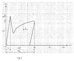
- a force-displacement curve ie a force-displacement diagram, are determined, the course of which below with reference to a in FIG. 4 1, in which the force on the Y-axis and the path on the X-axis of the force-displacement diagram is illustrated will be explained.
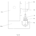
- FIGS. 3a to 3e illustrates a typical task that can be performed with such a press 100.
- the basic principle of a pressing process is described, in which a press ring 10 is pressed onto a shaft 20 to secure a pushed onto the shaft 20 sleeve 30 with a predetermined axial play a, so produce a press bond as he in FIG. 3e is shown as the end product.
- FIG. 3a shows the insertion of the shaft 20 in the lower tool 115 of the press 100.
- the ram 116 is raised to facilitate the insertion of the shaft 20.
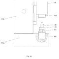
- the sleeve 30 is pushed onto the shaft 20, which is to be secured with the press ring 10.
- the pressing ring 10 is placed on the front side of the shaft 20 and the pressing process, which is carried out in two steps in this example performed to allow a correction for the spring back of the press 100 when breaking the press ring 10 started.
- the pressing ring 10 is touched by the ram 116, whereby the zero position of the pressing path by which the control is to move the ram 116 in the first sub-step, at least provisionally defined.
- the first sub-step begins, and the pressing ring 10 is pressed to a pre-position V.
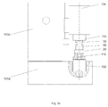
- the state reached after these steps is in Figure 3c shown.
- a force-displacement diagram is available, which is used to correct the pressing path as a function of parameters of this pressing process.
- the current axial play of the sleeve can be determined by moving on the shaft. This axial clearance measurement can be determined either by means of a measuring device integrated in the press or by removing the component composite.
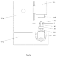
- the quill 104 or the pressing die 116 is then moved to the resulting "residual pressing" in at least one further step, at the end of which then the plunger 116 is moved back. The state reached after these steps is in 3d figure shown.
- Phase 1 begins with the probing of the press ring 10 with the ram 116 inserted into the sleeve 104. From this point, a force builds up continuously, which leads to the deformation of all components located in the drive train. These are on the one hand the system-related components of the press 100, so spindle 106, thrust bearing, engine clutch, load cell 102 and C-frame 101 and on the other hand, the components to be pressed together. In this phase, the path s1 of the ram-and thus also of the sleeve 104- is covered.
- Phase 2 begins as soon as the force with which the press 100 is working is sufficient to overcome these holding forces. If this force, referred to as the breakaway force L, is reached, the "break-free" of the press ring 10 occurs, which means that it sets in motion and thus no longer counteracts its static friction but its sliding friction counteracts the movement. As a consequence, there is a sudden loss of power in the Pressing compound in which the pressing ring 10 temporarily precedes the pressing die 116 or the sleeve 104 moving therefrom. The pressing die 116 moves the path s2 back in this phase.
- Phase 3 begins with the press ram 116 reaching the press ring 10 again.
- the acting force begins to increase until a constant sliding speed is reached at which the acting force is in equilibrium with the sliding friction force.
- the distance s3 is covered.
- Phase 4 begins with the control of the press 100 decelerating the ram 116 or ram 104, respectively, by driving the servo motor 108 to reduce the speed of the pressing operation to zero. Accordingly, the speed of the ram 116 or quill 104 decreases until it comes to a standstill.
- the pressing ring 10 is now at its end position and is connected to the shaft 20 by holding forces, in particular static friction forces. But it still acts on this position a force on the 40 Pressverbund, namely the setting force S.
- phase 1 namely, only the pressing punch 116, but not the pressing ring 10, moves. Accordingly, the travel path of the sleeve 104 given as a control variable must be corrected. Due to a fixed correction value, which is identical for all pressing operations of a component series, this can not be achieved precisely as a consequence of component tolerances. It is immediately apparent that e.g. a press ring 10 with oversize on a shaft 20 with undersize a significantly lower breakout force L will need as a press ring 10 with Unterschauf a shaft 20 with excess.
- the pressing process is divided into two sub-steps.
- the extraction of the relevant parameters from the force-displacement curve of the first step is possible and the correction can then be made in the second sub-step.
- the punch hits the pressing ring and tries to displace the pressing ring. This builds up a continuous force until reaching the breakout force L on. During the buildup of force, a distance is covered, which causes an elastic deformation within the press as well as in the component assembly, referred to as pressing system. This elastic deformation is not converted into a movement of the press ring. This distance is referred to as the death path T.
- the press ring After breakaway of the press ring there is a sudden drop in the pressing force.
- the press ring has the static friction overcome and undergoes during sliding the force of sliding friction.
- the ram moves to the predetermined position, which corresponds to the predetermined press travel of 80 microns. After reaching the end position, the punch moves back. Here, the press and the component network is continuously relieved.
- the characteristic during the discharge has the same slope as during the build-up of force.
- the pressing process just described leads in practice to the following result:
- the path specification (the predetermined pressing path PW before ) was: 80 ⁇ m.
- the death path T was 15 ⁇ m.
- the press travel calculated and controlled by the controller was 80 ⁇ m, but the effective effective press travel PW eff was only 70 ⁇ m. Since the effective distance of the component displacement is 70 ⁇ m, the target position was not achieved by 10 ⁇ m in this pressing method.
- the effective pressing path PW eff is too small by 10 ⁇ m.
- the procedure is essentially the same as that associated with FIG. 5 described procedure. After breakaway of the press ring there is a sudden drop in the pressing force. This drop in force is detected by the press control and the distance corresponding to the death path T calculated. This death path T is described by the breakaway force and the origin of the force-displacement curve. This dead-end T is added once during the ongoing pressing process.
- the pressing process just described leads in practice to the following result:
- the Wegvorgabe for press punches was 80 ⁇ m.
- the death path was 15 ⁇ m, which the press control has recognized and taken into account.
- the effective travel distance of the component displacement of 85 ⁇ m that an improvement in the deviation compared to the pressing process without dead-time compensation was achieved in the pressing method with dynamic Todwegkompensation, but exceeded the target position by 5 microns.
- the effective pressing path PW eff is too wide by 5 ⁇ m.
- the pressing process two sub-steps, namely in a pre-pressing VP and a final pressing EP, divided.
- the characteristic values "breakout force" L and "setting force” S become from the generated force-displacement characteristic determined.
- a second pressing step in which the components are to be selectively displaced by 80 microns to each other, the compensation with a force-dependent correction value, which was determined by the differential force .DELTA.F of breakout force L and S setting applied to Todwegkompensation.
- the differential force ⁇ F breakaway force L - setting force S
- ⁇ F breakaway force L - setting force S
- the setting force S is smaller than the breakaway force L, this causes a springback of the pressing system.
- the setting force S is greater than the breakaway force L, the preload in the press system is increased. This causes e.g. a larger bend of the C-frame.
- the values for the look-up table can be determined either by graphical evaluation of force-displacement curves or by empirical values obtained in test pressings.
- a displacement of the components to each other by 80 microns is to be achieved in the compression of two components, wherein the pressing process two sub-steps, namely in a pre-pressing VP and a final pressing EP, is divided.
- the parameter "setting force" S is determined from the generated force-displacement characteristic curve.
- the force characteristic is analyzed in the rising and falling force edge around the breakaway force L in the form that the corresponding path information corresponding to the force level of the setting force S, are determined. From this path information the difference ⁇ s is calculated.
- This differential path corresponds to the partial relaxation (springback) of the pressing system, as well as the composite component, due to different levels of force when breaking loose or when setting the component.
- a second pressing step in which the components are to be displaced specifically by 80 .mu.m to each other, the compensation with the difference path .DELTA.s, which is caused by a partial relaxation of the pressing system, is used for Todwegkompensation additionally.
- the path specification of the punch contains the desired pressing path in the amount of 80 ⁇ m, the dynamic dead-end compensation as well as the compensation of the differential path ⁇ s.
- the differential path ⁇ s is determined from the force-displacement curve of the pre-compression and applied automatically at the final pressure.
Landscapes
- Engineering & Computer Science (AREA)
- Mechanical Engineering (AREA)
- Chemical & Material Sciences (AREA)
- Analytical Chemistry (AREA)
- Physics & Mathematics (AREA)
- General Physics & Mathematics (AREA)
- Control Of Presses (AREA)
Applications Claiming Priority (1)
| Application Number | Priority Date | Filing Date | Title |
|---|---|---|---|
| DE102014110507.9A DE102014110507A1 (de) | 2014-07-25 | 2014-07-25 | Pressverfahren mit Kompensation von Positionierfehlern bei einem Pressvorgang und Presse zur Durchführung eines solchen Verfahrens |
Publications (2)
| Publication Number | Publication Date |
|---|---|
| EP2977196A1 true EP2977196A1 (fr) | 2016-01-27 |
| EP2977196B1 EP2977196B1 (fr) | 2022-11-16 |
Family
ID=53719692
Family Applications (1)
| Application Number | Title | Priority Date | Filing Date |
|---|---|---|---|
| EP15177634.1A Active EP2977196B1 (fr) | 2014-07-25 | 2015-07-21 | Procede de moulage a compensation d'erreurs de positionnement lors du processus de moulage et presse destinee a executer un tel procede |
Country Status (6)
| Country | Link |
|---|---|
| EP (1) | EP2977196B1 (fr) |
| DE (1) | DE102014110507A1 (fr) |
| ES (1) | ES2933050T3 (fr) |
| HU (1) | HUE060620T2 (fr) |
| PL (1) | PL2977196T3 (fr) |
| PT (1) | PT2977196T (fr) |
Cited By (2)
| Publication number | Priority date | Publication date | Assignee | Title |
|---|---|---|---|---|
| CN110355555A (zh) * | 2019-08-27 | 2019-10-22 | 安徽合力股份有限公司 | 一种叉车门架槽钢的滚轮压装机构 |
| CN118809169A (zh) * | 2024-09-14 | 2024-10-22 | 宁波明鑫电器机械制造有限公司 | 一种用于生产转向机压块的自动组装机 |
Families Citing this family (1)
| Publication number | Priority date | Publication date | Assignee | Title |
|---|---|---|---|---|
| WO2020058087A1 (fr) * | 2018-09-21 | 2020-03-26 | Kistler Holding Ag | Procédé pour l'analyse d'état d'un système d'assemblage électromécanique et système d'assemblage électromécanique pour la mise en œuvre de ce procédé |
Citations (5)
| Publication number | Priority date | Publication date | Assignee | Title |
|---|---|---|---|---|
| US5123165A (en) * | 1991-03-21 | 1992-06-23 | Amp Incorporated | Method of determining the crimp height of a crimped electrical connection |
| US5491647A (en) * | 1992-01-07 | 1996-02-13 | Signature Technologies, Inc. | Method and apparatus for controlling a press |
| DE19705462A1 (de) * | 1997-02-13 | 1998-08-20 | Schmidt Feinmech | Verfahren zum Betreiben einer Elektropresse |
| US5813263A (en) * | 1993-10-15 | 1998-09-29 | Komatsu, Ltd. | Ram position setting method and ram control unit for press brake |
| US20110132207A1 (en) * | 2009-12-08 | 2011-06-09 | Martin Schmeink | Plunger drive with load profile adaptation |
Family Cites Families (9)
| Publication number | Priority date | Publication date | Assignee | Title |
|---|---|---|---|---|
| SU1433744A1 (ru) * | 1986-08-01 | 1988-10-30 | Куйбышевский политехнический институт им.В.В.Куйбышева | Способ управлени процессом запрессовки на механическом прессе |
| DE9014783U1 (de) * | 1990-10-25 | 1992-02-20 | Robert Bosch Gmbh, 7000 Stuttgart | Motorgetriebene Presse mit Kraft- und Wegsensoren |
| US6276050B1 (en) * | 1998-07-20 | 2001-08-21 | Emhart Inc. | Riveting system and process for forming a riveted joint |
| JP3504167B2 (ja) * | 1998-12-01 | 2004-03-08 | 太陽鉄工株式会社 | 圧入の良否の判定方法及び判定装置 |
| JP2001232525A (ja) * | 2000-02-23 | 2001-08-28 | Fuji Heavy Ind Ltd | 圧入装置 |
| EP2099584B1 (fr) * | 2006-07-18 | 2017-10-25 | Kistler Holding AG | Unité d'assemblage |
| EP2295198B1 (fr) * | 2009-09-15 | 2013-11-13 | Sonplas GmbH | Dispositif et procédé destinés à l'assemblage et/ou au traitement d'un joint à ajustement serré |
| JP5382359B2 (ja) * | 2010-04-28 | 2014-01-08 | 株式会社安川電機 | ロボットシステム |
| JP5466582B2 (ja) * | 2010-06-08 | 2014-04-09 | 株式会社神戸製鋼所 | ブッシュ圧入検査装置、その検査方法、その検査プログラムならびにブッシュ圧入装置 |
-
2014
- 2014-07-25 DE DE102014110507.9A patent/DE102014110507A1/de not_active Ceased
-
2015
- 2015-07-21 HU HUE15177634A patent/HUE060620T2/hu unknown
- 2015-07-21 EP EP15177634.1A patent/EP2977196B1/fr active Active
- 2015-07-21 PL PL15177634.1T patent/PL2977196T3/pl unknown
- 2015-07-21 ES ES15177634T patent/ES2933050T3/es active Active
- 2015-07-21 PT PT151776341T patent/PT2977196T/pt unknown
Patent Citations (5)
| Publication number | Priority date | Publication date | Assignee | Title |
|---|---|---|---|---|
| US5123165A (en) * | 1991-03-21 | 1992-06-23 | Amp Incorporated | Method of determining the crimp height of a crimped electrical connection |
| US5491647A (en) * | 1992-01-07 | 1996-02-13 | Signature Technologies, Inc. | Method and apparatus for controlling a press |
| US5813263A (en) * | 1993-10-15 | 1998-09-29 | Komatsu, Ltd. | Ram position setting method and ram control unit for press brake |
| DE19705462A1 (de) * | 1997-02-13 | 1998-08-20 | Schmidt Feinmech | Verfahren zum Betreiben einer Elektropresse |
| US20110132207A1 (en) * | 2009-12-08 | 2011-06-09 | Martin Schmeink | Plunger drive with load profile adaptation |
Cited By (2)
| Publication number | Priority date | Publication date | Assignee | Title |
|---|---|---|---|---|
| CN110355555A (zh) * | 2019-08-27 | 2019-10-22 | 安徽合力股份有限公司 | 一种叉车门架槽钢的滚轮压装机构 |
| CN118809169A (zh) * | 2024-09-14 | 2024-10-22 | 宁波明鑫电器机械制造有限公司 | 一种用于生产转向机压块的自动组装机 |
Also Published As
| Publication number | Publication date |
|---|---|
| PT2977196T (pt) | 2022-12-21 |
| PL2977196T3 (pl) | 2023-01-30 |
| DE102014110507A1 (de) | 2016-01-28 |
| ES2933050T3 (es) | 2023-01-31 |
| HUE060620T2 (hu) | 2023-04-28 |
| EP2977196B1 (fr) | 2022-11-16 |
Similar Documents
| Publication | Publication Date | Title |
|---|---|---|
| DE69309610T2 (de) | Verfahren und Vorrichtung zum Messen und Einstellen der Presskräfte an einer Presse | |
| DE69509818T2 (de) | Verfahren und Gerät zur Optimierung der Betriebsbedingungen einer Presse auf der Basis der Pressebetriebsumgebung und/oder des Blechzustandes | |
| DE3781887T2 (de) | Adaptivsteuerungssystem fuer hydraulische abkantpresse. | |
| DE4015196C2 (de) | Presse mit piezoelektrischen Aktuatoren und Steuerung derselben | |
| DE69306640T2 (de) | Methode und Apparat zur Haltekraftmessung an einem Druckring einer Presse | |
| EP0403038B1 (fr) | Procédé et dispositif pour fabriquer des articles pressés à dimensions exactes | |
| DE102008035301B3 (de) | Pulverpresse | |
| DE3537234C2 (fr) | ||
| EP2977196B1 (fr) | Procede de moulage a compensation d'erreurs de positionnement lors du processus de moulage et presse destinee a executer un tel procede | |
| EP0353479B1 (fr) | Procédé et dispositif pour réduire la charge de presse dans une presse à découper comportant des butées fixes | |
| AT515672B1 (de) | Biegepresse | |
| DE4331403A1 (de) | Verfahren zum Verbinden dünner Platten und Vorrichtung zur Durchführung des Verfahrens | |
| DE102019125562A1 (de) | Stanznietvorrichtung und verfahren zum betreiben einer stanznietvorrichtung, um eine inkorrekte matrizenverwendung zu verhindern | |
| DE102008011375A1 (de) | Antriebseinrichtung für eine Presse | |
| DE102011055630B4 (de) | Kniehebelpresse mit Verstellvorrichtung für ein Werkzeugteil | |
| EP1048450A2 (fr) | Procédé pour déterminer la position d'un poinçon dans une presse à poudre | |
| EP0820823B1 (fr) | Dispositif de contrÔle, notamment pour machines de formage | |
| DE3244171C2 (fr) | ||
| EP0699490B1 (fr) | Dispositif de commande, en particulier pour machines de formage | |
| DE69329807T2 (de) | Verfahren und Gerät zum Anpassen der Betriebsbedingungen einer Presse je nach benutzten Formen | |
| WO2003072278A1 (fr) | Procede de reduction des erreurs d'angle de pliage lors du pliage | |
| WO1998035791A1 (fr) | Procedes et dispositif pour produire des assemblages par vis | |
| EP2329895A2 (fr) | Presse et outil doté d'un dispositif de retenue pour une pièce usinée | |
| DE102022105378B4 (de) | Vorrichtung und Verfahren zur Ermittlung einer Längenänderung und/oder einer Deformation innerhalb eines Bauteils | |
| EP1439055A2 (fr) | Méthode pour la régulation de la position finale dans une presse pour des articles moulés ayant une dimension exacte |
Legal Events
| Date | Code | Title | Description |
|---|---|---|---|
| PUAI | Public reference made under article 153(3) epc to a published international application that has entered the european phase |
Free format text: ORIGINAL CODE: 0009012 |
|
| AK | Designated contracting states |
Kind code of ref document: A1 Designated state(s): AL AT BE BG CH CY CZ DE DK EE ES FI FR GB GR HR HU IE IS IT LI LT LU LV MC MK MT NL NO PL PT RO RS SE SI SK SM TR |
|
| AX | Request for extension of the european patent |
Extension state: BA ME |
|
| 17P | Request for examination filed |
Effective date: 20160725 |
|
| RBV | Designated contracting states (corrected) |
Designated state(s): AL AT BE BG CH CY CZ DE DK EE ES FI FR GB GR HR HU IE IS IT LI LT LU LV MC MK MT NL NO PL PT RO RS SE SI SK SM TR |
|
| STAA | Information on the status of an ep patent application or granted ep patent |
Free format text: STATUS: EXAMINATION IS IN PROGRESS |
|
| 17Q | First examination report despatched |
Effective date: 20180515 |
|
| REG | Reference to a national code |
Ref country code: DE Ref legal event code: R079 Ref document number: 502015016155 Country of ref document: DE Free format text: PREVIOUS MAIN CLASS: B30B0015140000 Ipc: B23P0019020000 |
|
| GRAP | Despatch of communication of intention to grant a patent |
Free format text: ORIGINAL CODE: EPIDOSNIGR1 |
|
| STAA | Information on the status of an ep patent application or granted ep patent |
Free format text: STATUS: GRANT OF PATENT IS INTENDED |
|
| RIC1 | Information provided on ipc code assigned before grant |
Ipc: G01L 5/00 20060101ALI20220524BHEP Ipc: B30B 15/26 20060101ALI20220524BHEP Ipc: B30B 15/14 20060101ALI20220524BHEP Ipc: B23P 19/02 20060101AFI20220524BHEP |
|
| INTG | Intention to grant announced |
Effective date: 20220621 |
|
| GRAS | Grant fee paid |
Free format text: ORIGINAL CODE: EPIDOSNIGR3 |
|
| GRAA | (expected) grant |
Free format text: ORIGINAL CODE: 0009210 |
|
| STAA | Information on the status of an ep patent application or granted ep patent |
Free format text: STATUS: THE PATENT HAS BEEN GRANTED |
|
| AK | Designated contracting states |
Kind code of ref document: B1 Designated state(s): AL AT BE BG CH CY CZ DE DK EE ES FI FR GB GR HR HU IE IS IT LI LT LU LV MC MK MT NL NO PL PT RO RS SE SI SK SM TR |
|
| REG | Reference to a national code |
Ref country code: GB Ref legal event code: FG4D Free format text: NOT ENGLISH |
|
| REG | Reference to a national code |
Ref country code: CH Ref legal event code: EP |
|
| REG | Reference to a national code |
Ref country code: IE Ref legal event code: FG4D Free format text: LANGUAGE OF EP DOCUMENT: GERMAN |
|
| REG | Reference to a national code |
Ref country code: DE Ref legal event code: R096 Ref document number: 502015016155 Country of ref document: DE |
|
| REG | Reference to a national code |
Ref country code: AT Ref legal event code: REF Ref document number: 1531496 Country of ref document: AT Kind code of ref document: T Effective date: 20221215 |
|
| REG | Reference to a national code |
Ref country code: PT Ref legal event code: SC4A Ref document number: 2977196 Country of ref document: PT Date of ref document: 20221221 Kind code of ref document: T Free format text: AVAILABILITY OF NATIONAL TRANSLATION Effective date: 20221214 |
|
| REG | Reference to a national code |
Ref country code: NL Ref legal event code: FP |
|
| REG | Reference to a national code |
Ref country code: ES Ref legal event code: FG2A Ref document number: 2933050 Country of ref document: ES Kind code of ref document: T3 Effective date: 20230131 |
|
| REG | Reference to a national code |
Ref country code: SK Ref legal event code: T3 Ref document number: E 41076 Country of ref document: SK |
|
| REG | Reference to a national code |
Ref country code: LT Ref legal event code: MG9D |
|
| PG25 | Lapsed in a contracting state [announced via postgrant information from national office to epo] |
Ref country code: SE Free format text: LAPSE BECAUSE OF FAILURE TO SUBMIT A TRANSLATION OF THE DESCRIPTION OR TO PAY THE FEE WITHIN THE PRESCRIBED TIME-LIMIT Effective date: 20221116 Ref country code: NO Free format text: LAPSE BECAUSE OF FAILURE TO SUBMIT A TRANSLATION OF THE DESCRIPTION OR TO PAY THE FEE WITHIN THE PRESCRIBED TIME-LIMIT Effective date: 20230216 Ref country code: LT Free format text: LAPSE BECAUSE OF FAILURE TO SUBMIT A TRANSLATION OF THE DESCRIPTION OR TO PAY THE FEE WITHIN THE PRESCRIBED TIME-LIMIT Effective date: 20221116 Ref country code: FI Free format text: LAPSE BECAUSE OF FAILURE TO SUBMIT A TRANSLATION OF THE DESCRIPTION OR TO PAY THE FEE WITHIN THE PRESCRIBED TIME-LIMIT Effective date: 20221116 |
|
| REG | Reference to a national code |
Ref country code: HU Ref legal event code: AG4A Ref document number: E060620 Country of ref document: HU |
|
| PG25 | Lapsed in a contracting state [announced via postgrant information from national office to epo] |
Ref country code: RS Free format text: LAPSE BECAUSE OF FAILURE TO SUBMIT A TRANSLATION OF THE DESCRIPTION OR TO PAY THE FEE WITHIN THE PRESCRIBED TIME-LIMIT Effective date: 20221116 Ref country code: LV Free format text: LAPSE BECAUSE OF FAILURE TO SUBMIT A TRANSLATION OF THE DESCRIPTION OR TO PAY THE FEE WITHIN THE PRESCRIBED TIME-LIMIT Effective date: 20221116 Ref country code: IS Free format text: LAPSE BECAUSE OF FAILURE TO SUBMIT A TRANSLATION OF THE DESCRIPTION OR TO PAY THE FEE WITHIN THE PRESCRIBED TIME-LIMIT Effective date: 20230316 Ref country code: HR Free format text: LAPSE BECAUSE OF FAILURE TO SUBMIT A TRANSLATION OF THE DESCRIPTION OR TO PAY THE FEE WITHIN THE PRESCRIBED TIME-LIMIT Effective date: 20221116 Ref country code: GR Free format text: LAPSE BECAUSE OF FAILURE TO SUBMIT A TRANSLATION OF THE DESCRIPTION OR TO PAY THE FEE WITHIN THE PRESCRIBED TIME-LIMIT Effective date: 20230217 |
|
| PG25 | Lapsed in a contracting state [announced via postgrant information from national office to epo] |
Ref country code: SM Free format text: LAPSE BECAUSE OF FAILURE TO SUBMIT A TRANSLATION OF THE DESCRIPTION OR TO PAY THE FEE WITHIN THE PRESCRIBED TIME-LIMIT Effective date: 20221116 Ref country code: RO Free format text: LAPSE BECAUSE OF FAILURE TO SUBMIT A TRANSLATION OF THE DESCRIPTION OR TO PAY THE FEE WITHIN THE PRESCRIBED TIME-LIMIT Effective date: 20221116 Ref country code: EE Free format text: LAPSE BECAUSE OF FAILURE TO SUBMIT A TRANSLATION OF THE DESCRIPTION OR TO PAY THE FEE WITHIN THE PRESCRIBED TIME-LIMIT Effective date: 20221116 Ref country code: DK Free format text: LAPSE BECAUSE OF FAILURE TO SUBMIT A TRANSLATION OF THE DESCRIPTION OR TO PAY THE FEE WITHIN THE PRESCRIBED TIME-LIMIT Effective date: 20221116 |
|
| REG | Reference to a national code |
Ref country code: DE Ref legal event code: R097 Ref document number: 502015016155 Country of ref document: DE |
|
| PG25 | Lapsed in a contracting state [announced via postgrant information from national office to epo] |
Ref country code: AL Free format text: LAPSE BECAUSE OF FAILURE TO SUBMIT A TRANSLATION OF THE DESCRIPTION OR TO PAY THE FEE WITHIN THE PRESCRIBED TIME-LIMIT Effective date: 20221116 |
|
| PLBE | No opposition filed within time limit |
Free format text: ORIGINAL CODE: 0009261 |
|
| STAA | Information on the status of an ep patent application or granted ep patent |
Free format text: STATUS: NO OPPOSITION FILED WITHIN TIME LIMIT |
|
| 26N | No opposition filed |
Effective date: 20230817 |
|
| PG25 | Lapsed in a contracting state [announced via postgrant information from national office to epo] |
Ref country code: SI Free format text: LAPSE BECAUSE OF FAILURE TO SUBMIT A TRANSLATION OF THE DESCRIPTION OR TO PAY THE FEE WITHIN THE PRESCRIBED TIME-LIMIT Effective date: 20221116 |
|
| PG25 | Lapsed in a contracting state [announced via postgrant information from national office to epo] |
Ref country code: MC Free format text: LAPSE BECAUSE OF FAILURE TO SUBMIT A TRANSLATION OF THE DESCRIPTION OR TO PAY THE FEE WITHIN THE PRESCRIBED TIME-LIMIT Effective date: 20221116 |
|
| PG25 | Lapsed in a contracting state [announced via postgrant information from national office to epo] |
Ref country code: MC Free format text: LAPSE BECAUSE OF FAILURE TO SUBMIT A TRANSLATION OF THE DESCRIPTION OR TO PAY THE FEE WITHIN THE PRESCRIBED TIME-LIMIT Effective date: 20221116 |
|
| PG25 | Lapsed in a contracting state [announced via postgrant information from national office to epo] |
Ref country code: BG Free format text: LAPSE BECAUSE OF FAILURE TO SUBMIT A TRANSLATION OF THE DESCRIPTION OR TO PAY THE FEE WITHIN THE PRESCRIBED TIME-LIMIT Effective date: 20221116 |
|
| PG25 | Lapsed in a contracting state [announced via postgrant information from national office to epo] |
Ref country code: BG Free format text: LAPSE BECAUSE OF FAILURE TO SUBMIT A TRANSLATION OF THE DESCRIPTION OR TO PAY THE FEE WITHIN THE PRESCRIBED TIME-LIMIT Effective date: 20221116 |
|
| PGFP | Annual fee paid to national office [announced via postgrant information from national office to epo] |
Ref country code: PT Payment date: 20250625 Year of fee payment: 11 |
|
| PG25 | Lapsed in a contracting state [announced via postgrant information from national office to epo] |
Ref country code: CY Free format text: LAPSE BECAUSE OF FAILURE TO SUBMIT A TRANSLATION OF THE DESCRIPTION OR TO PAY THE FEE WITHIN THE PRESCRIBED TIME-LIMIT; INVALID AB INITIO Effective date: 20150721 |
|
| PGFP | Annual fee paid to national office [announced via postgrant information from national office to epo] |
Ref country code: SK Payment date: 20250624 Year of fee payment: 11 |
|
| PGFP | Annual fee paid to national office [announced via postgrant information from national office to epo] |
Ref country code: HU Payment date: 20250714 Year of fee payment: 11 |
|
| PGFP | Annual fee paid to national office [announced via postgrant information from national office to epo] |
Ref country code: NL Payment date: 20250723 Year of fee payment: 11 Ref country code: LU Payment date: 20250722 Year of fee payment: 11 |
|
| PGFP | Annual fee paid to national office [announced via postgrant information from national office to epo] |
Ref country code: ES Payment date: 20250819 Year of fee payment: 11 |
|
| PGFP | Annual fee paid to national office [announced via postgrant information from national office to epo] |
Ref country code: DE Payment date: 20250821 Year of fee payment: 11 |
|
| PGFP | Annual fee paid to national office [announced via postgrant information from national office to epo] |
Ref country code: IT Payment date: 20250731 Year of fee payment: 11 |
|
| PGFP | Annual fee paid to national office [announced via postgrant information from national office to epo] |
Ref country code: BE Payment date: 20250722 Year of fee payment: 11 Ref country code: GB Payment date: 20250724 Year of fee payment: 11 |
|
| PGFP | Annual fee paid to national office [announced via postgrant information from national office to epo] |
Ref country code: FR Payment date: 20250723 Year of fee payment: 11 Ref country code: AT Payment date: 20250721 Year of fee payment: 11 |
|
| PGFP | Annual fee paid to national office [announced via postgrant information from national office to epo] |
Ref country code: CH Payment date: 20250724 Year of fee payment: 11 |
|
| PGFP | Annual fee paid to national office [announced via postgrant information from national office to epo] |
Ref country code: IE Payment date: 20250723 Year of fee payment: 11 Ref country code: CZ Payment date: 20250710 Year of fee payment: 11 |
|
| PG25 | Lapsed in a contracting state [announced via postgrant information from national office to epo] |
Ref country code: TR Free format text: LAPSE BECAUSE OF FAILURE TO SUBMIT A TRANSLATION OF THE DESCRIPTION OR TO PAY THE FEE WITHIN THE PRESCRIBED TIME-LIMIT Effective date: 20221116 |