EP2978637B1 - Système de brancard de toit - Google Patents
Système de brancard de toit Download PDFInfo
- Publication number
- EP2978637B1 EP2978637B1 EP14712662.7A EP14712662A EP2978637B1 EP 2978637 B1 EP2978637 B1 EP 2978637B1 EP 14712662 A EP14712662 A EP 14712662A EP 2978637 B1 EP2978637 B1 EP 2978637B1
- Authority
- EP
- European Patent Office
- Prior art keywords
- roof
- roof rail
- rail
- cover member
- cover
- Prior art date
- Legal status (The legal status is an assumption and is not a legal conclusion. Google has not performed a legal analysis and makes no representation as to the accuracy of the status listed.)
- Active
Links
Images


Classifications
-
- B—PERFORMING OPERATIONS; TRANSPORTING
- B60—VEHICLES IN GENERAL
- B60R—VEHICLES, VEHICLE FITTINGS, OR VEHICLE PARTS, NOT OTHERWISE PROVIDED FOR
- B60R9/00—Supplementary fittings on vehicle exterior for carrying loads, e.g. luggage, sports gear or the like
- B60R9/04—Carriers associated with vehicle roof
Definitions
- This invention relates to a vehicle and a roof rail system for a vehicle. Aspects of the invention relate to a system, to a method and to a vehicle.
- a typical roof rail system comprises at least two parallel rails which are located on the sides of the roof of the vehicle and aligned parallel to the length of the vehicle.
- One or more supporting members (such as roof bars) may be connected to the rails so that they extend across the vehicle.
- a rack or box can typically be secured to the supporting members.
- a supporting member may itself comprise a box or container connected direct to the rail system. Items such as roof-boxes, bicycles, ski equipment, luggage and other supplies can then be fastened to, or contained within, the supporting member(s), significantly increasing the carrying capacity of the vehicle.
- roof rail systems are designed to be detachable, such that they can be added to or removed from the vehicle as desired. However it is desirable to be able to attach such rails without major work upon the vehicle, so that a fitting can be done quickly and simply. In particular, it is desirable to avoid removing the upholstery from ceiling inside the vehicle, since this is difficult and risks damaging the upholstery.
- the roof rail system may be bolted to the roof using anchor points located in a channel in the roof.
- US6267281 B1 discloses a roof rail system which consists of a side rail which engages with a roof channel.
- Such systems are often awkward to install, since they require bolts to be fastened in tight spaces with poor access, such as within the roof channel itself. This is done to hide the bolts from view, and so preserve a better appearance for the vehicle.
- some rail systems comprise "end caps", which are removable pieces at the end of each rail which can be used to hide any bolts from view.
- the end caps are always visibly separate from the rail to which they are attached, since the join is visible. This is considered to be ugly by many consumers, and hence is undesirable on premium vehicles. Caps are also vulnerable to being knocked off, especially when fitting a roof rack or box, or when loading heavy goods onto the roof of the vehicle.
- US 5 732 863 discloses a roof support assembly in which an inner side rail and an outer trim rail are each affixed to a centre support and the assembly is fastened to the roof from above by screw means.
- a roof rail system for a vehicle as defined in claim 1.
- the invention provides a roof rail system which can be fitted to the roof of a vehicle and still provide a desirable appearance.
- the brackets are hidden by the cover and the rail, protecting them from damage while the good appearance of the rail system is preserved since no bolts or other necessary but ugly fixing components are visible.
- the rail comprises a first lip, at top edge of the first cover member being located alongside the first lip.
- the lip runs along the length of an inner curve of the rail.
- Locating the cover against the first lip hides the edge of the cover, and helps to maintain a premium appearance in the roof rail.
- the upstanding flange is covered in that it is hidden from external view.
- views of the flange are hidden by rail bends, while the top view and one side view are hidden by the rail.
- a further side view is hidden by the first cover, and a view from beneath is hidden by the roof of the vehicle.
- first cover member is retained at least in part by the first lip.
- the roof rail system comprises at least one locating member, the locating member being positioned so as to urge the first cover member against the first lip. This will help to keep rain water and other environmental factors out of the roof rail system. It also prevents a visible gap from developing between the cover and the lip, which might spoil the appearance of the roof rail system.
- the rail comprises a locating member.
- the roof comprises a locating member.
- the first cover member comprises a locating member. Any combination of these components may comprise locating members.
- the rail, the roof or the first cover member comprise a first locating member
- a second cover member comprises a second locating member
- the first locating member being arranged to abut against the second locating member and so urge the first cover member against the first lip.
- the rail comprises at least one first indentation, a portion of the first cover member being located within the first indentation.
- the roof comprises a second lip, the first cover member being located against the second lip. It may be that the first and second lips form a substantially continuous lip. Where the roof comprises a second lip, it may be that the first cover member is retained at least in part by the second lip. It may further be that the roof rail system comprises at least one locating member, the locating member being positioned so as to urge the first cover member against the second lip.
- the roof rail system may comprise separate locating members for urging the first cover member against the first lip and for urging the first cover member against the second lip. Alternatively, a locating member may urge the first cover member against both the first and second lips.
- the vehicle comprises a roof ditch, the location points on the roof of the vehicle being located within the roof ditch.
- the roof rail system further comprises a ditch cover member adapted to cover the ditch when the roof rail system is in use. It may further be that a portion of the first cover member is located within the roof ditch. It may be that the ditch cover member comprises a locating member. It may be that the ditch cover member comprises a second lip. It may be that a bottom edge of the first cover member is located on the ditch cover member.
- the roof rail system further comprises at least one clip system, the clip system securing the first cover member with respect to the rail.
- the roof rail system comprises a locating member
- the locating member may comprise the clip
- the clip system comprises a first clip on the cover and a second clip on the rail, which clip system snaps into engagement by said movement of the first cover member relative to the roof rail in a direction transverse said longitudinal direction.
- roof rail and first cover member further comprise locating members which abut one another on said movement of the first cover member relative to the roof rail in a direction transverse said longitudinal direction to lever said top edge into engagement with said lip.
- the longitudinal direction is one substantially parallel to the rail.
- the rail is an elongate shape, the majority of whose surface area comprises a plurality of substantially parallel surfaces, the longitudinal direction being defined with respect to these surfaces.
- connection of the first cover member to the roof rail is by movement of the first cover member relative to the roof rail in a direction orthogonal to the roof rail.
- the rail and the roof define at least a plurality of apertures, each aperture being substantially covered by the first cover member.
- the bracket may be affixed to the location points using bolts, welding, chemical adhesion or any other suitable method.
- a method of installing a roof rail system on a vehicle comprising a roof rail system as described above.
- the vehicle may comprise at least two of said brackets spaced along the roof, said first cover member, when fitted, covering both of said brackets, and covering any gap between the roof and rail.
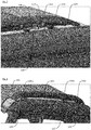
- FIG. 1 shows a section of a roof 101 of a vehicle which comprises a roof rail system 102 according to the invention.
- the roof rail system comprises a rail 103 and a first cover member 104 which are fitted to the roof 101.
- the roof 101 of the vehicle comprises a ditch 105, which is an elongate intrusion set into the surface of the roof. If the vehicle is not fitted with a roof rail system 102, then the ditch 105 is provided with a first ditch finisher (not shown).
- a ditch finisher is an elongate member which fits into and covers the ditch 105 so as to provide the roof 101 of the vehicle with a smooth profile.
- the first ditch finisher is removed in order to access the ditch 105.
- a bracket 106 (three of them in each ditch of the embodiment illustrated) is then installed in the ditch, as shown in Figure 2 .
- the bracket 106 comprises a base 134, an upstanding flange 135 and an upper portion 136.
- the bracket is secured within the ditch using roof bolts 107.
- the ditch includes roof fixing adaptors 108 which are securely attached to the roof.
- a further fixing part (not shown) may be provided under the roof to retain the fixing adapter 108 in place.
- Each roof bolt 107 is fastened into a roof fixing adapter 108 to secure the bracket to the roof 101.
- Vehicles may be provided to customers with the roof fixing adaptors 108 already fitted, so that fixing of a roof rail does not need to involve access to the inside of the roof 101 through the head liner.
- Brackets 106 may be installed.
- a second, different ditch finisher 109 also referred to as a second cover member
- the rail 103 is fitted to the brackets as shown in Figure 3 .
- the second ditch finisher 109 comprises holes 120 which fit around the brackets 106 and through which at least the upstanding flanges 135 protrude.
- the rail 103 comprises anchor points 110 which can be fastened to the brackets 106 using rail bolts 111.
- the second cover member may be retained in position by the ends of the rail 103 and/or by clips (not shown).
- Figure 4 shows the full extent of the ditch finisher 109 and the rail 103 as fitted on the roof 101.
- the rail 103 is retained by three brackets 106, a front bracket 106a, a centre bracket 106b and a rear bracket 106c.
- the first cover member 104 is fitted as shown in figure 1 .
- the rail 103 and the roof 101 define a space which contains the brackets 106.
- the cover 104 substantially covers this space.
- FIG. 5 shows a first cross section through the roof rail system 102, showing the rail 103, the cover 104 and the second ditch finisher 109.
- the second ditch finisher 109 comprises deformable feet 112 which are made of rubber or similar elastomeric material. The feet 112 fit snugly against the sides of the ditch 105 and help to prevent rain water collecting beneath the second ditch finisher 109.
- the rail 103 comprises a first clip 113.
- the cover 104 comprises a second clip 114.
- the two clips 113, 114 are pushed together and deform, allowing the two clips to slide past one another.
- the two clips 113, 114 then snap into engagement as shown in Figure 5 , retaining the cover 104 in place with respect to the rail 103.
- the rail 103 further comprises a lip 115 and a first locating member 116.
- the lip 115 runs for most of the length of the rail 103, along the top of the space formed between the rail 103 and the roof 101.
- the lip therefore defines an indentation 132 in the rail in which a top edge of the cover 104 is received.
- the cover 104 comprises a second locating member 117.
- the rail 103 and the cover 104 are shaped such that, when the two clips 113, 114 are engaged, the first locating member 116 abuts against the second locating member 117. This tends to urge the cover 104 towards the lip 115 of the rail 103.
- the cover 104 is made from a flexible plastics material, and as such it tends to bend outwards slightly, urging the upper portion of the cover 104 against the inner surface of the lip 115.
- the cover 104 smoothly blends the roof 101 and the ditch finisher 109 into the rail 103 so that to all appearances the roof rail is, at least in shape, an extension of the roof, providing a clean and uncluttered appearance different from traditional roof rails that tend to be upstanding and separate from (but obviously connected to) the roof.
- the rail 103 is a simple elongate shape which can be easily produced using extrusion methods, with holes machined into the rail for fixings as appropriate once the rail 103 is extruded.
- the cover 104 is also a simple shape, and can be easily manufactured using injection moulding methods.
- the rail 103 may also comprise a cross piece 133 and a floor 137 which structurally support the rail and helps to prevent buckling.
- the floor 137 may also seat on and (further) retain the second ditch finisher 109.
- Figure 6 shows a further cross section through the rail system 102, this time at a point which includes a bracket 106, a roof bolt 107 and a roof fixing adapter 108.
- part of the floor 137 and clip 113, as well as part of the cross piece 133 of the rail 103, is cut away at this point to accommodate the bracket 106.
- the second ditch finisher 109 here comprises a hole 120 for the bracket 106 to extend through.
- the roof bolt 107 is fastened through the bracket into the roof fixing adapter 108, which is itself fastened into the roof.
- bracket 106 and the roof bolt 107 is attached before the rail 103 is put in place. This provides the person installing the roof rail system with easy access to place and fasten the roof bolt 107, without obstruction from the rail 103.
- the bracket 106 is hidden from view by the rail 106 and the cover 104.
- the cover 104 appears to be part of the rail, and since both the cover 104 and the rail 103 rest against the ditch finisher 109, the rail 103 appears substantially flush with the roof 101.
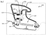
- Figure 7 shows a still further cross section through the rail system 102, this time at a point which includes a bracket 106 and a rail bolt 111.
- the rail bolt 111 passes through a hole 121 which has been machined into the rail 103, and a further hole 122 in the bracket.
- a threaded rail fixing adapter 118 is fixed at the rear of the bracket behind the hole 122 and is engaged by the bolt 111, such that the rail 103 is retained against the bracket 106.
- the rail bolt 111 is attached before the cover 104 is put in place. This provides the person installing the roof rail system with easy access to place and fasten the rail bolt 111, without obstruction from the cover 104.
- the cover 104 then hides the bolts 111, and indeed the entire bracket 106 and the holes 120 in the second ditch cover 109.
- the lip 115 of the rail 103 serves to hide the top of the cover 104, such that there is no discernible gap between the cover 104 and the rail 103. This provides a premium appearance for the vehicle, since the cover 104 and the rail 103 appear to be a single piece.
- the lip 115 also hides the exact location of the top of the cover 104, such that the top of the cover can move by several millimetres without spoiling the appearance of the system 102.
- the rail therefore has a tolerance of several millimetres in both its alignment and its exact dimensions.
- the bracket 106 also comprises an upper portion 136. As is shown in Figure 6 , the upper portion 136 of the bracket 106 abuts with an inner surface 131 of the rail 103. The upper portion 136 of the bracket 106 therefore assists in retaining the rail 103 in position. For example, when a load is attached to the rail 103, and the vehicle is driven over a bump, the load tends to rise up relative to the vehicle, exerting an upwards pull on the rail 103. This pull is resisted by the upper portion 136 of the bracket 106, helping to retain the rail 103 in position.
- the inclined upper portion 136 requires that initial fitting of the rail over the upstanding flange 135 of the bracket 106 involves rotating (in an anti-clockwise direction when referring to Figure 6 ) the rail from a slightly inclined start position to its final vertical position shown in Figure 6 . This enables the bottom edge of the cut-out floor 137 to clear the retainer 118 (which ultimately is located in a channel 123 formed by the cut-out between the cross piece 133 and floor 137) and so that the inner surface 131 can engage under the correspondingly inclined upper portion 136.
- the embodiment above comprises a first locating member 116 and a second locating member 117 which are located on the roof rail 103 and the cover 104 respectively.
- there may be no second locating member 117 and the first locating member 116 may be longer so that it abuts the inner surface of the cover 104.
- the ditch finisher 109 may comprise a first locating member which extends upwards from the ditch finisher, through a hole provided in a rail 103, and abuts either with a second locating member 117 or the inner surface of the cover 104.
- the positioning of the clips 113, 114 and the locating members 116, 117 urges the upper portion of the cover 104 against the inner surface of the lip 115 and, in addition, also causes the bottom edge of the first cover member 104 to be pressed against the top of the second ditch finisher 109.
- the skilled man would understand that only one of the upper edge and the lower edge need be urged into contact with either the lip or the ditch finisher, respectively.
Landscapes
- Engineering & Computer Science (AREA)
- Mechanical Engineering (AREA)
- Fittings On The Vehicle Exterior For Carrying Loads, And Devices For Holding Or Mounting Articles (AREA)
Claims (14)
- Système de brancard de toit (102) pour un véhicule, le système de brancard de toit comprenant :au moins un support (106), le support étant adapté pour être fixé à des points de localisation sur le toit d'un véhicule ;un brancard de toit (103), pour un raccordement au support et ayant une direction longitudinale ; etun premier organe de couvercle (104), pour un raccordement au brancard de toit une fois que le brancard de toit est raccordé au support, caractérisé en ce quele support a une bride à la verticale (135) pour un raccordement au brancard de toit, et le brancard de toit et le premier organe de couvercle, lorsque le brancard de toit est raccordé à la bride à la verticale et lorsque le premier organe de couvercle est raccordé au brancard de toit, couvrent la bride à la verticale et le raccordement de la bride et du brancard de toit, etun raccordement du premier organe de couvercle avec le brancard de toit se fait par déplacement du premier organe de couvercle par rapport au brancard de toit dans une direction transversale à ladite direction longitudinale, une fois que le brancard de toit est raccordé au support.
- Système de brancard de toit selon la revendication 1, dans lequel le brancard comprend une première lèvre (115), un bord supérieur du premier organe de couvercle (104) étant situé le long de la première lèvre.
- Système de brancard de toit selon la revendication 2, dans lequel le premier organe de couvercle (104) est retenu au moins en partie par la première lèvre (115).
- Système de brancard de toit selon la revendication 2 ou la revendication 3, comprenant au moins un organe de localisation (116), l'organe de localisation étant positionné de façon à pousser le premier organe de couvercle (104) contre la première lèvre (115).
- Système de brancard de toit selon l'une quelconque des revendications précédentes, pour son utilisation avec un véhicule qui comprend une rigole de toit (105) et les points de localisation sur le toit du véhicule sont situés au sein de la rigole de toit, dans lequel le système de brancard de toit comprend en outre un organe de couvercle de rigole (109) adapté pour couvrir la rigole lorsque le système de brancard de toit est en utilisation.
- Système de brancard de toit selon la revendication 5, dans lequel un bord inférieur du premier organe de couvercle (104) est situé sur l'organe de couvercle de rigole (109).
- Système de brancard de toit selon l'une quelconque des revendications précédentes, dans lequel le système de brancard de toit comprend en outre au moins un système de pinces (113, 114), le système de pinces arrimant le premier élément couvrant par rapport au brancard.
- Système de brancard de toit selon la revendication 7, dans lequel le système de pinces comprend une première pince (114) sur le couvercle (104) et une seconde pince (113) sur le brancard (103), lequel système de pinces s'emboîte en enclenchement par ledit déplacement du premier organe de couvercle (104) par rapport au brancard de toit (103) dans une direction transversale à ladite direction longitudinale.
- Système de brancard de toit selon les revendications 2 et 8, dans lequel ledit brancard de toit (103) et ledit premier organe de couvercle (104) comprennent en outre des organes de localisation (116, 117) qui butent les uns contre les autres lors dudit déplacement du premier organe de couvercle par rapport au brancard de toit dans une direction transversale à ladite direction longitudinale pour pousser par effet de levier ledit bord supérieur en enclenchement avec ladite lèvre.
- Système de brancard de toit selon les revendications 6 et 9, dans lequel, lors dudit déplacement du premier organe de couvercle (104) par rapport au brancard de toit dans une direction transversale à ladite direction longitudinale, ledit bord inférieur est poussé par effet de levier en enclenchement avec ledit organe de couvercle de rigole (109).
- Système de brancard de toit selon l'une quelconque des revendications précédentes, dans lequel la direction longitudinale est parallèle au brancard et dans lequel ladite direction transversale est sensiblement orthogonale au brancard de toit.
- Procédé d'installation d'un système de brancard de toit (102) sur un véhicule, le procédé comprenant les étapes :la fourniture d'un système de brancard de toit selon l'une quelconque des revendications précédentes ;la fixation de l'au moins un support (106) au toit ;la fixation du brancard (103) à la bride à la verticale (135) de l'au moins un support (106) ; etune fois que le brancard est raccordé à la bride, le raccordement du premier organe de couvercle (104) au brancard de toit par déplacement du premier organe de couvercle par rapport au brancard de toit dans une direction transversale à la direction longitudinale du brancard de toit.
- Véhicule comprenant un système de brancard de toit (102) selon l'une quelconque des revendications 1 à 11.
- Véhicule selon la revendication 13, comprenant au moins deux desdits supports (106) espacés le long du toit, ledit premier organe de couvercle (104), lorsqu'il est installé, couvre lesdits deux supports, et couvrant tout écartement entre le toit et le brancard (103).
Applications Claiming Priority (2)
| Application Number | Priority Date | Filing Date | Title |
|---|---|---|---|
| GB1305518.1A GB2512335B (en) | 2013-03-26 | 2013-03-26 | Roof rail system |
| PCT/EP2014/055961 WO2014154688A1 (fr) | 2013-03-26 | 2014-03-25 | Système de brancard de toit |
Publications (2)
| Publication Number | Publication Date |
|---|---|
| EP2978637A1 EP2978637A1 (fr) | 2016-02-03 |
| EP2978637B1 true EP2978637B1 (fr) | 2018-05-16 |
Family
ID=48326688
Family Applications (1)
| Application Number | Title | Priority Date | Filing Date |
|---|---|---|---|
| EP14712662.7A Active EP2978637B1 (fr) | 2013-03-26 | 2014-03-25 | Système de brancard de toit |
Country Status (3)
| Country | Link |
|---|---|
| EP (1) | EP2978637B1 (fr) |
| GB (1) | GB2512335B (fr) |
| WO (1) | WO2014154688A1 (fr) |
Cited By (1)
| Publication number | Priority date | Publication date | Assignee | Title |
|---|---|---|---|---|
| DE202018104554U1 (de) | 2018-08-08 | 2019-10-02 | WKW Erbslöh Automotive GmbH | Lösbare Befestigungsanordnung einer Dachreling am Dach eines Kraftfahrzeugs |
Families Citing this family (4)
| Publication number | Priority date | Publication date | Assignee | Title |
|---|---|---|---|---|
| GB2533383A (en) * | 2014-12-18 | 2016-06-22 | Bentley Motors Ltd | Roof rail |
| DE202015004902U1 (de) * | 2015-07-08 | 2016-10-13 | GM Global Technology Operations LLC (n. d. Ges. d. Staates Delaware) | Dachreling zur lösbaren Befestigung am Dachrahmen eines Kraftfahrzeugs |
| EP3360731B1 (fr) | 2017-02-10 | 2020-02-05 | DURA Operating, LLC | Barre de toit |
| US10363881B2 (en) * | 2017-05-30 | 2019-07-30 | Dura Operating, Llc | Automobile roof rail and seal system |
Citations (1)
| Publication number | Priority date | Publication date | Assignee | Title |
|---|---|---|---|---|
| US5732863A (en) * | 1996-04-19 | 1998-03-31 | Advanced Accessory Systems Llc | Article carrier assembly |
Family Cites Families (4)
| Publication number | Priority date | Publication date | Assignee | Title |
|---|---|---|---|---|
| US4341332A (en) * | 1980-12-29 | 1982-07-27 | Four Star Corporation | Stanchion assembly |
| JPH10250490A (ja) * | 1997-03-11 | 1998-09-22 | Nissan Motor Co Ltd | ルーフラックレール取付構造 |
| DE19858558B4 (de) * | 1998-12-18 | 2006-04-13 | Jac Products Deutschland Gmbh | Dachreling für Fahrzeuge |
| DE202007001742U1 (de) * | 2007-02-07 | 2007-04-05 | WKW Erbslöh Automotive GmbH | Dachträgeranordnung |
-
2013
- 2013-03-26 GB GB1305518.1A patent/GB2512335B/en active Active
-
2014
- 2014-03-25 WO PCT/EP2014/055961 patent/WO2014154688A1/fr not_active Ceased
- 2014-03-25 EP EP14712662.7A patent/EP2978637B1/fr active Active
Patent Citations (1)
| Publication number | Priority date | Publication date | Assignee | Title |
|---|---|---|---|---|
| US5732863A (en) * | 1996-04-19 | 1998-03-31 | Advanced Accessory Systems Llc | Article carrier assembly |
Cited By (1)
| Publication number | Priority date | Publication date | Assignee | Title |
|---|---|---|---|---|
| DE202018104554U1 (de) | 2018-08-08 | 2019-10-02 | WKW Erbslöh Automotive GmbH | Lösbare Befestigungsanordnung einer Dachreling am Dach eines Kraftfahrzeugs |
Also Published As
| Publication number | Publication date |
|---|---|
| EP2978637A1 (fr) | 2016-02-03 |
| GB201305518D0 (en) | 2013-05-08 |
| GB2512335A (en) | 2014-10-01 |
| GB2512335B (en) | 2016-08-24 |
| WO2014154688A1 (fr) | 2014-10-02 |
Similar Documents
| Publication | Publication Date | Title |
|---|---|---|
| EP2978637B1 (fr) | Système de brancard de toit | |
| CA2816268C (fr) | Systeme de montage de barres | |
| US6862825B1 (en) | Mounting of flexible display panels | |
| US20080179911A1 (en) | Adapter rail for soft rollup tonneau covers | |
| US20190225136A1 (en) | Resilient cover clip | |
| US20160281365A1 (en) | Snow Guard | |
| US20150075587A1 (en) | Method for attaching a photovoltaic panel | |
| US10124743B2 (en) | Monument fixtures | |
| US20100237116A1 (en) | Versatile leg for a roof rack | |
| US12214883B2 (en) | Monument fixtures | |
| US20170225556A1 (en) | Vehicle door | |
| WO2008025500A2 (fr) | Dispositif permettant de sécuriser un chargement et procédé d'installation dudit système | |
| US7004537B2 (en) | Molding apparatus for vehicles and methods for use | |
| EP2653072A2 (fr) | Ensemble de montage d'article | |
| US9174591B2 (en) | Roof molding | |
| EP1894773A1 (fr) | Système modular pour véhicule de service | |
| US8832939B2 (en) | Spring latch and method for attaching a seat cushion to a seat frame | |
| RU2624395C2 (ru) | Передний бампер автотранспортного средства с установленной на нем отделочной планкой | |
| US8430048B2 (en) | Line guard apparatus | |
| US8622445B1 (en) | Rub rail assembly | |
| US9387743B2 (en) | Slide lock attachment system | |
| GB2512012A (en) | Glazing system and methods | |
| US20180112694A1 (en) | Mounting arrangement | |
| AU2013251243B2 (en) | Utility Vehicle Tub Canopy Attachment Assembly | |
| JP2009121069A (ja) | 防護柵 |
Legal Events
| Date | Code | Title | Description |
|---|---|---|---|
| PUAI | Public reference made under article 153(3) epc to a published international application that has entered the european phase |
Free format text: ORIGINAL CODE: 0009012 |
|
| 17P | Request for examination filed |
Effective date: 20151026 |
|
| AK | Designated contracting states |
Kind code of ref document: A1 Designated state(s): AL AT BE BG CH CY CZ DE DK EE ES FI FR GB GR HR HU IE IS IT LI LT LU LV MC MK MT NL NO PL PT RO RS SE SI SK SM TR |
|
| AX | Request for extension of the european patent |
Extension state: BA ME |
|
| DAX | Request for extension of the european patent (deleted) | ||
| STAA | Information on the status of an ep patent application or granted ep patent |
Free format text: STATUS: EXAMINATION IS IN PROGRESS |
|
| 17Q | First examination report despatched |
Effective date: 20170310 |
|
| GRAP | Despatch of communication of intention to grant a patent |
Free format text: ORIGINAL CODE: EPIDOSNIGR1 |
|
| STAA | Information on the status of an ep patent application or granted ep patent |
Free format text: STATUS: GRANT OF PATENT IS INTENDED |
|
| INTG | Intention to grant announced |
Effective date: 20171127 |
|
| GRAS | Grant fee paid |
Free format text: ORIGINAL CODE: EPIDOSNIGR3 |
|
| GRAA | (expected) grant |
Free format text: ORIGINAL CODE: 0009210 |
|
| STAA | Information on the status of an ep patent application or granted ep patent |
Free format text: STATUS: THE PATENT HAS BEEN GRANTED |
|
| AK | Designated contracting states |
Kind code of ref document: B1 Designated state(s): AL AT BE BG CH CY CZ DE DK EE ES FI FR GB GR HR HU IE IS IT LI LT LU LV MC MK MT NL NO PL PT RO RS SE SI SK SM TR |
|
| REG | Reference to a national code |
Ref country code: GB Ref legal event code: FG4D |
|
| REG | Reference to a national code |
Ref country code: CH Ref legal event code: EP |
|
| REG | Reference to a national code |
Ref country code: IE Ref legal event code: FG4D |
|
| REG | Reference to a national code |
Ref country code: DE Ref legal event code: R096 Ref document number: 602014025520 Country of ref document: DE |
|
| REG | Reference to a national code |
Ref country code: AT Ref legal event code: REF Ref document number: 999241 Country of ref document: AT Kind code of ref document: T Effective date: 20180615 |
|
| REG | Reference to a national code |
Ref country code: NL Ref legal event code: MP Effective date: 20180516 |
|
| REG | Reference to a national code |
Ref country code: LT Ref legal event code: MG4D |
|
| PG25 | Lapsed in a contracting state [announced via postgrant information from national office to epo] |
Ref country code: SE Free format text: LAPSE BECAUSE OF FAILURE TO SUBMIT A TRANSLATION OF THE DESCRIPTION OR TO PAY THE FEE WITHIN THE PRESCRIBED TIME-LIMIT Effective date: 20180516 Ref country code: ES Free format text: LAPSE BECAUSE OF FAILURE TO SUBMIT A TRANSLATION OF THE DESCRIPTION OR TO PAY THE FEE WITHIN THE PRESCRIBED TIME-LIMIT Effective date: 20180516 Ref country code: LT Free format text: LAPSE BECAUSE OF FAILURE TO SUBMIT A TRANSLATION OF THE DESCRIPTION OR TO PAY THE FEE WITHIN THE PRESCRIBED TIME-LIMIT Effective date: 20180516 Ref country code: NO Free format text: LAPSE BECAUSE OF FAILURE TO SUBMIT A TRANSLATION OF THE DESCRIPTION OR TO PAY THE FEE WITHIN THE PRESCRIBED TIME-LIMIT Effective date: 20180816 Ref country code: FI Free format text: LAPSE BECAUSE OF FAILURE TO SUBMIT A TRANSLATION OF THE DESCRIPTION OR TO PAY THE FEE WITHIN THE PRESCRIBED TIME-LIMIT Effective date: 20180516 Ref country code: BG Free format text: LAPSE BECAUSE OF FAILURE TO SUBMIT A TRANSLATION OF THE DESCRIPTION OR TO PAY THE FEE WITHIN THE PRESCRIBED TIME-LIMIT Effective date: 20180816 |
|
| PG25 | Lapsed in a contracting state [announced via postgrant information from national office to epo] |
Ref country code: NL Free format text: LAPSE BECAUSE OF FAILURE TO SUBMIT A TRANSLATION OF THE DESCRIPTION OR TO PAY THE FEE WITHIN THE PRESCRIBED TIME-LIMIT Effective date: 20180516 Ref country code: HR Free format text: LAPSE BECAUSE OF FAILURE TO SUBMIT A TRANSLATION OF THE DESCRIPTION OR TO PAY THE FEE WITHIN THE PRESCRIBED TIME-LIMIT Effective date: 20180516 Ref country code: RS Free format text: LAPSE BECAUSE OF FAILURE TO SUBMIT A TRANSLATION OF THE DESCRIPTION OR TO PAY THE FEE WITHIN THE PRESCRIBED TIME-LIMIT Effective date: 20180516 Ref country code: GR Free format text: LAPSE BECAUSE OF FAILURE TO SUBMIT A TRANSLATION OF THE DESCRIPTION OR TO PAY THE FEE WITHIN THE PRESCRIBED TIME-LIMIT Effective date: 20180817 Ref country code: LV Free format text: LAPSE BECAUSE OF FAILURE TO SUBMIT A TRANSLATION OF THE DESCRIPTION OR TO PAY THE FEE WITHIN THE PRESCRIBED TIME-LIMIT Effective date: 20180516 |
|
| REG | Reference to a national code |
Ref country code: AT Ref legal event code: MK05 Ref document number: 999241 Country of ref document: AT Kind code of ref document: T Effective date: 20180516 |
|
| PG25 | Lapsed in a contracting state [announced via postgrant information from national office to epo] |
Ref country code: AT Free format text: LAPSE BECAUSE OF FAILURE TO SUBMIT A TRANSLATION OF THE DESCRIPTION OR TO PAY THE FEE WITHIN THE PRESCRIBED TIME-LIMIT Effective date: 20180516 Ref country code: DK Free format text: LAPSE BECAUSE OF FAILURE TO SUBMIT A TRANSLATION OF THE DESCRIPTION OR TO PAY THE FEE WITHIN THE PRESCRIBED TIME-LIMIT Effective date: 20180516 Ref country code: EE Free format text: LAPSE BECAUSE OF FAILURE TO SUBMIT A TRANSLATION OF THE DESCRIPTION OR TO PAY THE FEE WITHIN THE PRESCRIBED TIME-LIMIT Effective date: 20180516 Ref country code: RO Free format text: LAPSE BECAUSE OF FAILURE TO SUBMIT A TRANSLATION OF THE DESCRIPTION OR TO PAY THE FEE WITHIN THE PRESCRIBED TIME-LIMIT Effective date: 20180516 Ref country code: SK Free format text: LAPSE BECAUSE OF FAILURE TO SUBMIT A TRANSLATION OF THE DESCRIPTION OR TO PAY THE FEE WITHIN THE PRESCRIBED TIME-LIMIT Effective date: 20180516 Ref country code: CZ Free format text: LAPSE BECAUSE OF FAILURE TO SUBMIT A TRANSLATION OF THE DESCRIPTION OR TO PAY THE FEE WITHIN THE PRESCRIBED TIME-LIMIT Effective date: 20180516 Ref country code: PL Free format text: LAPSE BECAUSE OF FAILURE TO SUBMIT A TRANSLATION OF THE DESCRIPTION OR TO PAY THE FEE WITHIN THE PRESCRIBED TIME-LIMIT Effective date: 20180516 |
|
| REG | Reference to a national code |
Ref country code: DE Ref legal event code: R097 Ref document number: 602014025520 Country of ref document: DE |
|
| PG25 | Lapsed in a contracting state [announced via postgrant information from national office to epo] |
Ref country code: IT Free format text: LAPSE BECAUSE OF FAILURE TO SUBMIT A TRANSLATION OF THE DESCRIPTION OR TO PAY THE FEE WITHIN THE PRESCRIBED TIME-LIMIT Effective date: 20180516 Ref country code: SM Free format text: LAPSE BECAUSE OF FAILURE TO SUBMIT A TRANSLATION OF THE DESCRIPTION OR TO PAY THE FEE WITHIN THE PRESCRIBED TIME-LIMIT Effective date: 20180516 |
|
| REG | Reference to a national code |
Ref country code: GB Ref legal event code: 746 Effective date: 20190208 |
|
| PLBE | No opposition filed within time limit |
Free format text: ORIGINAL CODE: 0009261 |
|
| STAA | Information on the status of an ep patent application or granted ep patent |
Free format text: STATUS: NO OPPOSITION FILED WITHIN TIME LIMIT |
|
| 26N | No opposition filed |
Effective date: 20190219 |
|
| PGFP | Annual fee paid to national office [announced via postgrant information from national office to epo] |
Ref country code: IT Payment date: 20181029 Year of fee payment: 18 |
|
| PG25 | Lapsed in a contracting state [announced via postgrant information from national office to epo] |
Ref country code: SI Free format text: LAPSE BECAUSE OF FAILURE TO SUBMIT A TRANSLATION OF THE DESCRIPTION OR TO PAY THE FEE WITHIN THE PRESCRIBED TIME-LIMIT Effective date: 20180516 |
|
| PG25 | Lapsed in a contracting state [announced via postgrant information from national office to epo] |
Ref country code: MC Free format text: LAPSE BECAUSE OF FAILURE TO SUBMIT A TRANSLATION OF THE DESCRIPTION OR TO PAY THE FEE WITHIN THE PRESCRIBED TIME-LIMIT Effective date: 20180516 |
|
| REG | Reference to a national code |
Ref country code: CH Ref legal event code: PL |
|
| PG25 | Lapsed in a contracting state [announced via postgrant information from national office to epo] |
Ref country code: LU Free format text: LAPSE BECAUSE OF NON-PAYMENT OF DUE FEES Effective date: 20190325 Ref country code: AL Free format text: LAPSE BECAUSE OF FAILURE TO SUBMIT A TRANSLATION OF THE DESCRIPTION OR TO PAY THE FEE WITHIN THE PRESCRIBED TIME-LIMIT Effective date: 20180516 |
|
| REG | Reference to a national code |
Ref country code: BE Ref legal event code: MM Effective date: 20190331 |
|
| PG25 | Lapsed in a contracting state [announced via postgrant information from national office to epo] |
Ref country code: IE Free format text: LAPSE BECAUSE OF NON-PAYMENT OF DUE FEES Effective date: 20190325 Ref country code: LI Free format text: LAPSE BECAUSE OF NON-PAYMENT OF DUE FEES Effective date: 20190331 Ref country code: CH Free format text: LAPSE BECAUSE OF NON-PAYMENT OF DUE FEES Effective date: 20190331 |
|
| PG25 | Lapsed in a contracting state [announced via postgrant information from national office to epo] |
Ref country code: FR Free format text: LAPSE BECAUSE OF NON-PAYMENT OF DUE FEES Effective date: 20190331 Ref country code: BE Free format text: LAPSE BECAUSE OF NON-PAYMENT OF DUE FEES Effective date: 20190331 |
|
| PG25 | Lapsed in a contracting state [announced via postgrant information from national office to epo] |
Ref country code: TR Free format text: LAPSE BECAUSE OF FAILURE TO SUBMIT A TRANSLATION OF THE DESCRIPTION OR TO PAY THE FEE WITHIN THE PRESCRIBED TIME-LIMIT Effective date: 20180516 |
|
| PG25 | Lapsed in a contracting state [announced via postgrant information from national office to epo] |
Ref country code: PT Free format text: LAPSE BECAUSE OF FAILURE TO SUBMIT A TRANSLATION OF THE DESCRIPTION OR TO PAY THE FEE WITHIN THE PRESCRIBED TIME-LIMIT Effective date: 20180917 Ref country code: MT Free format text: LAPSE BECAUSE OF NON-PAYMENT OF DUE FEES Effective date: 20190325 |
|
| REG | Reference to a national code |
Ref country code: DE Ref legal event code: R119 Ref document number: 602014025520 Country of ref document: DE |
|
| PG25 | Lapsed in a contracting state [announced via postgrant information from national office to epo] |
Ref country code: DE Free format text: LAPSE BECAUSE OF NON-PAYMENT OF DUE FEES Effective date: 20201001 |
|
| PG25 | Lapsed in a contracting state [announced via postgrant information from national office to epo] |
Ref country code: CY Free format text: LAPSE BECAUSE OF FAILURE TO SUBMIT A TRANSLATION OF THE DESCRIPTION OR TO PAY THE FEE WITHIN THE PRESCRIBED TIME-LIMIT Effective date: 20180516 |
|
| PG25 | Lapsed in a contracting state [announced via postgrant information from national office to epo] |
Ref country code: IS Free format text: LAPSE BECAUSE OF FAILURE TO SUBMIT A TRANSLATION OF THE DESCRIPTION OR TO PAY THE FEE WITHIN THE PRESCRIBED TIME-LIMIT Effective date: 20180916 |
|
| PG25 | Lapsed in a contracting state [announced via postgrant information from national office to epo] |
Ref country code: HU Free format text: LAPSE BECAUSE OF FAILURE TO SUBMIT A TRANSLATION OF THE DESCRIPTION OR TO PAY THE FEE WITHIN THE PRESCRIBED TIME-LIMIT; INVALID AB INITIO Effective date: 20140325 |
|
| PG25 | Lapsed in a contracting state [announced via postgrant information from national office to epo] |
Ref country code: MK Free format text: LAPSE BECAUSE OF FAILURE TO SUBMIT A TRANSLATION OF THE DESCRIPTION OR TO PAY THE FEE WITHIN THE PRESCRIBED TIME-LIMIT Effective date: 20180516 |
|
| P01 | Opt-out of the competence of the unified patent court (upc) registered |
Effective date: 20230528 |
|
| PGFP | Annual fee paid to national office [announced via postgrant information from national office to epo] |
Ref country code: GB Payment date: 20260324 Year of fee payment: 13 |