EP2978986B1 - Kupplungsanordnung - Google Patents
Kupplungsanordnung Download PDFInfo
- Publication number
- EP2978986B1 EP2978986B1 EP14703875.6A EP14703875A EP2978986B1 EP 2978986 B1 EP2978986 B1 EP 2978986B1 EP 14703875 A EP14703875 A EP 14703875A EP 2978986 B1 EP2978986 B1 EP 2978986B1
- Authority
- EP
- European Patent Office
- Prior art keywords
- shaft
- splined shaft
- coupling
- splined
- shafts
- Prior art date
- Legal status (The legal status is an assumption and is not a legal conclusion. Google has not performed a legal analysis and makes no representation as to the accuracy of the status listed.)
- Active
Links
Images





Classifications
-
- F—MECHANICAL ENGINEERING; LIGHTING; HEATING; WEAPONS; BLASTING
- F16—ENGINEERING ELEMENTS AND UNITS; GENERAL MEASURES FOR PRODUCING AND MAINTAINING EFFECTIVE FUNCTIONING OF MACHINES OR INSTALLATIONS; THERMAL INSULATION IN GENERAL
- F16D—COUPLINGS FOR TRANSMITTING ROTATION; CLUTCHES; BRAKES
- F16D3/00—Yielding couplings, i.e. with means permitting movement between the connected parts during the drive
- F16D3/02—Yielding couplings, i.e. with means permitting movement between the connected parts during the drive adapted to specific functions
- F16D3/04—Yielding couplings, i.e. with means permitting movement between the connected parts during the drive adapted to specific functions specially adapted to allow radial displacement, e.g. Oldham couplings
-
- F—MECHANICAL ENGINEERING; LIGHTING; HEATING; WEAPONS; BLASTING
- F16—ENGINEERING ELEMENTS AND UNITS; GENERAL MEASURES FOR PRODUCING AND MAINTAINING EFFECTIVE FUNCTIONING OF MACHINES OR INSTALLATIONS; THERMAL INSULATION IN GENERAL
- F16D—COUPLINGS FOR TRANSMITTING ROTATION; CLUTCHES; BRAKES
- F16D1/00—Couplings for rigidly connecting two coaxial shafts or other movable machine elements
- F16D1/02—Couplings for rigidly connecting two coaxial shafts or other movable machine elements for connecting two abutting shafts or the like
-
- F—MECHANICAL ENGINEERING; LIGHTING; HEATING; WEAPONS; BLASTING
- F16—ENGINEERING ELEMENTS AND UNITS; GENERAL MEASURES FOR PRODUCING AND MAINTAINING EFFECTIVE FUNCTIONING OF MACHINES OR INSTALLATIONS; THERMAL INSULATION IN GENERAL
- F16D—COUPLINGS FOR TRANSMITTING ROTATION; CLUTCHES; BRAKES
- F16D3/00—Yielding couplings, i.e. with means permitting movement between the connected parts during the drive
- F16D3/02—Yielding couplings, i.e. with means permitting movement between the connected parts during the drive adapted to specific functions
- F16D3/10—Couplings with means for varying the angular relationship of two coaxial shafts during motion
-
- Y—GENERAL TAGGING OF NEW TECHNOLOGICAL DEVELOPMENTS; GENERAL TAGGING OF CROSS-SECTIONAL TECHNOLOGIES SPANNING OVER SEVERAL SECTIONS OF THE IPC; TECHNICAL SUBJECTS COVERED BY FORMER USPC CROSS-REFERENCE ART COLLECTIONS [XRACs] AND DIGESTS
- Y10—TECHNICAL SUBJECTS COVERED BY FORMER USPC
- Y10T—TECHNICAL SUBJECTS COVERED BY FORMER US CLASSIFICATION
- Y10T29/00—Metal working
- Y10T29/49—Method of mechanical manufacture
- Y10T29/49826—Assembling or joining
- Y10T29/49863—Assembling or joining with prestressing of part
- Y10T29/49874—Prestressing rod, filament or strand
-
- Y—GENERAL TAGGING OF NEW TECHNOLOGICAL DEVELOPMENTS; GENERAL TAGGING OF CROSS-SECTIONAL TECHNOLOGIES SPANNING OVER SEVERAL SECTIONS OF THE IPC; TECHNICAL SUBJECTS COVERED BY FORMER USPC CROSS-REFERENCE ART COLLECTIONS [XRACs] AND DIGESTS
- Y10—TECHNICAL SUBJECTS COVERED BY FORMER USPC
- Y10T—TECHNICAL SUBJECTS COVERED BY FORMER US CLASSIFICATION
- Y10T403/00—Joints and connections
- Y10T403/70—Interfitted members
- Y10T403/7026—Longitudinally splined or fluted rod
- Y10T403/7032—Longitudinally splined or fluted rod including a means, e.g., spring biased portion, for misalignment correction
Definitions
- the present invention relates to a clutch arrangement for coaxially connecting two shafts.
- a crankshaft of an internal combustion engine is coaxially connected to an armature shaft of an electrical machine.
- the invention relates to a method for assembling the clutch arrangement.
- the prior art knows various arrangements for connecting an internal combustion engine to an electrical machine in a motor vehicle.
- Belt drives are usually used in the prior art to connect the crankshaft to the armature shaft.
- the belt pulleys compensate for the torque fluctuations and for a play-free power transmission.
- the use of the belt drive and consequently also the non-coaxial arrangement of the electrical machine with respect to the internal combustion engine lead to a construction which does not save space.
- the belt drive is also prone to maintenance.
- the WO 2007/107138 A1 describes a torque transmission device with an input part and an output part, each of which can be connected to a rotatable shaft and is coupled in terms of drive by at least one intermediate element, which enables a radial displacement of the two parts.
- the intermediate element is coupled on the one hand to the input part and on the other hand to the output part by means of at least two radially elastic regions which enable radial displacement.
- the connection has the task Compensate for coaxiality errors (angular and axial misalignment) between the internal combustion engine and the electrical machine.
- a clutch arrangement comprising a first shaft, a second shaft and a clutch.
- the first shaft is in particular a crankshaft of an internal combustion engine in a motor vehicle.
- the second shaft is in particular an armature shaft of an electrical machine.
- the electrical machine is preferably operated as a high-voltage generator for generating electrical energy.
- the electrical machine can also be used as an electric motor for starting the internal combustion engine.
- the housing of the electrical machine is preferably connected directly to the crankshaft housing or the housing of the internal combustion engine.
- the two shafts are arranged coaxially. This very compact and space-saving arrangement of the internal combustion engine and the electrical machine requires a special coupling design.
- the clutch therefore comprises at least one moving element and one coupling element.
- the coupling element is arranged to be movable in the circumferential direction and / or in the radial direction.
- the movement element ensures that the coupling element rests or is pressed against the respective shaft without play in the circumferential direction or radial direction. Due to the play-free contact of the coupling element on the respective shaft, a torque can be transmitted without play between the two shafts.
- the movement element is a spring and / or a hydraulic pressure chamber.
- the spring and / or the hydraulic pressure chamber is arranged in the clutch and presses the clutch element against the first or second shaft, so that the play-free contact and thus the play-free power transmission are possible. Axial movements are also possible.
- the clutch comprises a first toothed shaft, a second toothed shaft and a third toothed shaft.
- the three splines form coupling elements.
- the first spline is spaced from the second spline.
- the third toothed shaft is located between the first toothed shaft and the second toothed shaft.
- the three splined shafts are arranged coaxially along the axis of rotation.
- the first toothed shaft is connected to the second toothed shaft via a torsion spring. Accordingly, the first toothed shaft and the second toothed shaft are each connected to the torsion spring in a rotationally fixed manner, for example via a polygon.
- the torsion spring forms the movement element.
- the torsion spring ensures that the first toothed shaft lies against the first shaft without play and the second toothed shaft lies against the second shaft without play; This is achieved by closing the power flow of the two shafts via the third splined shaft.
- the first shaft comprises a first shaft toothing and the second shaft comprises a second shaft toothing.
- the two shaft gears are in particular internal gears on the crankshaft and on the armature shaft.
- the first shaft toothing engages both the first toothed shaft and the third toothed shaft
- the second shaft toothing is engaged with the second toothed shaft and simultaneously with the third toothed shaft.
- the toothing is flank-centered and spherical at both ends of the toothed shaft 3.
- the third toothed shaft is preferably hollow on the inside.
- the torsion spring can extend through the third toothed shaft.
- the first splined shaft and the second splined shaft are located at the two ends of the torsion spring.
- the third toothed shaft is preferably rotatably arranged with respect to the torsion spring.
- the first toothed shaft and the second toothed shaft are preferably rotated relative to one another so that the torsion spring is tensioned.
- the first wave in particular Depending on the direction of rotation, the first shaft toothing lies either on the first spline or on the third spline.
- the second shaft toothing can rest either on the second toothed shaft or on the third toothed shaft.
- the different directions of rotation occur depending on whether the electrical machine is operated as a generator or a motor. Due to the fact that the tooth flanks of the first toothed shaft and the third toothed shaft or the second toothed shaft and the third toothed shaft are available to the shaft toothings, a play-free power transmission between the crankshaft and the armature shaft is possible.
- the clutch is designed as a cross disc clutch.
- the cross disc clutch is also referred to as the "Oldham clutch”.
- the coupling comprises a basic body.
- the base body comprises an extension on each side.
- the first extension is in a groove of the first shaft.
- the second extension is in a groove of the second shaft.
- the extensions stuck in the grooves make it possible to compensate for a radial and axial offset between the two shafts to a limited extent.
- the movement element is preferably a spring and / or a hydraulic pressure chamber.
- the coupling element is designed as at least one piston.
- the piston is guided in a linearly movable manner in the base body.
- the spring and / or the hydraulic pressure chamber ensure that the piston is pushed away from the base body. As a result, the piston rests in the groove of the respective shaft and ensures power transmission without play.
- At least one piston is provided on the side of the base body facing the first shaft, ie on the first extension, and that at least one piston is also arranged on the side facing the second shaft, ie on the second extension.
- a plurality of pistons are arranged in each of the two extensions of the base body.
- Each piston is loaded by at least one spring and can also be pressed outwards using its own hydraulic pressure chamber.
- Corresponding hydraulic channels in the base body ensure that the hydraulic pressure chambers are supplied with pressure.
- the Hydraulic pressure from the lubricant supply to the internal combustion engine is used.
- a preferred check valve in the hydraulic channels ensures sufficient maintenance of the pressure in the hydraulic pressure chambers below the individual pistons.
- Small outlet openings are preferably provided in the pistons. Hydraulic oil emerges from the hydraulic pressure chambers onto the surface of the pistons via these small outlet openings. This leads to a throttled release of the pressure in the hydraulic pressure chambers and at the same time to lubrication of the sliding surfaces between the clutch and the two shafts.
- the force of the springs or the force of the hydraulic pressure chambers need not be so great that the pistons are always pushed away from the base body. It is sufficient that the pistons rest against the two shafts at least when the direction of rotation changes. With increasing torque, the pistons are then pressed into the base body.
- the hydraulic oil is preferably conveyed out of the hydraulic pressure chambers through the outlet openings.
- the clutch is designed as a dog clutch.
- the clutch in this case comprises a first ring arranged in a rotationally fixed manner on the first shaft, a second ring arranged in a rotationally fixed manner on the second shaft and a compensating ring arranged between the two shafts.
- the compensating ring represents the movable coupling element.
- the first ring comprises first claws.
- the second ring includes second claws.
- the compensation ring includes compensation claws.
- the compensating ring is movable to a limited extent in relation to the two shafts.
- the first claws, the second claws and the compensating claws interlock. Depending on the size of the claws, limited compensation of radial and axial misalignment is possible.
- a compensating claw between a first claw and a second claw.
- a spring designed as a spiral compression spring or plate spring, is arranged.
- the spring is supported at one end against a second claw and at the other end against a compensating claw.
- the compensating claw in turn presses against a first claw, causing this first Claw is pressed against a next second claw.
- the spring thus serves to press the second claws against the first claws in the direction of the output useful torque.
- pockets are provided in the compensating claws, so that the springs can be partially arranged in these pockets.
- the springs When changing the direction of the moment, the springs are compressed so that they sit completely in the pockets. As a result, the compensating claws rest on the second claws.
- a cone clamping element is preferably used to mount the second ring on the second shaft.
- the first shaft is preferably conical.
- a matching inner cone is preferably formed on the first ring.
- a clamping screw and a clamping washer are preferably used.
- the clamping screw is preferably screwed into the first shaft on the end face in order to hold the first ring on the first shaft.
- the invention preferably comprises a control device for controlling and / or regulating the electrical machine, the control device being designed to control the electrical machine in order to compensate for rotational irregularities. For example, depending on the number of cylinders in the internal combustion engine, rotational irregularities occur on the crankshaft. These can be compensated for by controlling the electrical machine accordingly.
- the invention further comprises a method for assembling a clutch arrangement according to the first variant described above.
- This method comprises the following steps: (i) tensioning the torsion spring by rotating the first toothed shaft with respect to the second toothed shaft, (ii) inserting a first anti-twist device which fixes the first toothed shaft with respect to the third toothed shaft and a second anti-twist device with the second toothed shaft the third spline fixed, (iii) mounting the first spline on the first shaft and the second spline on the second shaft, and (iv) releasing the two anti-rotation devices.
- the two anti-rotation locks are released simultaneously with the mounting of the first and second toothed shafts on the first and second shafts.
- the anti-rotation device is shifted by inserting the respective splined shaft into the internal toothing on the crankshaft or armature shaft. This releases the anti-rotation lock.
- the anti-rotation device can be designed as a sleeve.
- the anti-rotation device can be designed as pins.
- the cuff is pushed on after tensioning the torsion spring, so that an internal toothing on the cuff simultaneously engages with the first spline and the third spline or with the second spline and the third spline.
- the sleeves are preferably pushed inwards. After assembly, the sleeves preferably sit completely on the third splined shaft. After assembly, the sleeves have no other function, but preferably remain on the third spline.
- the pins can be used as an alternative to the cuffs.
- the pins are inserted into the splines on the face. After tensioning the torsion spring, the pins are positioned so that they fix the first spline with respect to the third spline or the second spline with respect to the third spline, so that the torsion spring can no longer relax.
- the pins are shifted, in particular into the third splined shaft.
- the following procedure is provided for tensioning the torsion spring:
- the torsion spring is tensioned until a desired spring force is measured.
- the spring force remains almost constant over a wide "winding angle" and is mainly determined by the spring diameter.
- the first toothed shaft and / or second toothed shaft is then rotated further or turned back until the teeth of the three toothed shafts match, so that the sleeve can be pushed on.
- the pins turn back and forth until the holes of the pins are aligned, and as a result the pins can be inserted.
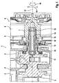
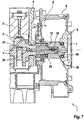
- the clutch arrangement comprises a first shaft 3, designed as a crankshaft of an internal combustion engine 2 in a motor vehicle.
- the first shaft 3 is arranged in a motor housing 4.
- the first shaft 3 is supported in the motor housing 4 via at least one bearing 5.
- the clutch arrangement 1 comprises a second shaft 7, designed as an armature shaft of an electrical machine 6.
- the electrical machine 6 is operated primarily as a high-voltage generator.
- the electrical machine 6 can also be operated by a motor in order to start the internal combustion engine 2.
- the electrical machine 6 comprises a generator housing 8.
- the second shaft 7 is mounted in this generator housing 8.
- the generator housing 8 is firmly connected to the motor housing 4 via a screw connection 9, which is only shown schematically.
- the two shafts 3, 7 are arranged coaxially. The arrangement is constructed as space-saving as possible.
- a coupling 10 is provided for the coaxial connection of the two shafts 3, 7.
- the clutch 10 projects into an internal toothing on the first shaft 3 and into an internal toothing on the second shaft 7.
- the generator housing 8 is placed so close to the motor housing 4 that the coupling 10 projects in the axial direction up to the bearing 5.
- An axis of rotation 17 is defined in accordance with the rotation of the two shafts 3, 7 and the clutch 10.
- a circumferential direction 18 is defined around the axis of rotation 17.
- a radial direction 19 is perpendicular to the axis of rotation 17.
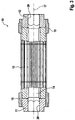
- the exact structure of the clutch 10 is in the Figures 2 and 3 shown.
- Fig. 3 shows a sectional view.
- the clutch 10 comprises a first toothed shaft 11, a second toothed shaft 12, a third toothed shaft 13 and a torsion spring 14.
- the third toothed shaft 13 is arranged along the axis of rotation 17 between the first toothed shaft 11 and the second toothed shaft 12.
- the torsion spring 14 is connected at its ends via a polygon 20 to the first toothed shaft 11 and the second toothed shaft 12 in a rotationally fixed manner.
- the third toothed shaft 13 is hollow on the inside, so that the torsion spring 14 can extend through the third toothed shaft 13.
- the Figures 2 and 3 show the clutch 10 in a state before it is mounted in the two shafts 3, 7.
- the Figures 2 and 3 are on both sides of the coupling 10 anti-rotation devices 15, designed as sleeves.
- the first toothed shaft 11 and the second toothed shaft 12 are rotated relative to one another, so that the torsion spring 14 is tensioned.
- the anti-rotation device 15 is pushed on both sides.
- the anti-rotation devices 15 engage in the toothing of the toothed shafts 11, 12, 13.
- the anti-rotation devices 15 are shifted inwards onto the third toothed shaft 13.
- the first toothed shaft 11 and the second toothed shaft 12 are no longer fixed relative to the third toothed shaft 13 and the torsion spring 14 can act, as a result of which the driven flank of the internal toothing of the crankshaft on the driven flank of toothed shaft 13 and the driven flank of the toothed shaft 13 on the one to be driven Flank of the internal toothing of the armature shaft is pressed with the spring force.
- the two anti-rotation locks 15 can remain without function on the third toothed shaft 13 after assembly.
- a plurality of lugs 16 are formed on the two anti-rotation devices 15. Devices must be provided on the first shaft 3 and / or on the second shaft 7 which engage these lugs 16 in order to adjust the anti-rotation locks 15 during assembly shift inside and transfer the holding force from the preload from the sleeves to the internal teeth.
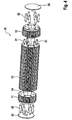
- Figures 4 to 6 show a further embodiment in which the clutch 10 comprises the three toothed shafts 11, 12, 13 and the torsion spring 14.
- Fig. 4 shows an exploded view of the clutch 10.
- Die Figures 5 and 6 show sectional views of the coupling 10 in different assembly states.
- the anti-rotation devices are designed as pins 21. After the first toothed shaft 11 and the second toothed shaft 12 have been rotated to tension the torsion spring 14, pins 21 are inserted in order to keep the torsion spring 14 in tension. This state is in Fig. 5 shown.
- mounting pins 22 are inserted at the end. These mounting pins 22 push the pins 21 further inward into the third toothed shaft 13. This releases the anti-rotation device and the torsion spring 14 can act.
- front mounting plates 23 are shown on both sides. These mounting plates 23 can also be components of the shafts 3, 7, so that the pins 21 are released simultaneously with the mounting of the coupling 10.
- the Figures 7 to 11 show exemplary embodiments in which the clutch 10 is designed as a cross disc clutch (also: Oldham clutch).
- Fig. 7 shows the coupling arrangement 1 with the coupling 10.
- the coupling 10 comprises a base body 24.
- the base body 24 has an extension 27, 28 at each of its two axial ends.
- the first extension 27 is in a first groove 25 in the first shaft 3.
- the second extension 28 is in a second groove 26 in the second shaft 7.
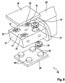
- Fig. 8 shows the first extension 27 of the base body 24 in detail.
- the second extension 28 is constructed in the same way, but rotated by 90 ° about the axis of rotation 17.
- the piston 29 represents a flat surface for the backlash-free system.
- knobs 30 are provided on the inside of the pistons 29.
- the knobs 30 are each in a hydraulic pressure chamber 31.
- a spring 32 designed as a plate spring. The springs 32 and the corresponding pressure in the hydraulic pressure chambers 31 push the pistons 29 away from the first extension 27.
- Fig. 9 shows a sectional view of hydraulic channels 33 for supplying pressure to the hydraulic chambers 31.
- a check valve 34 ensures sufficient pressure maintenance in the hydraulic pressure chambers 31. Hydraulic oil is preferably conveyed from the internal combustion engine 2 into the hydraulic channels 33 and thus into the hydraulic pressure chambers 31 via the check valve 34.
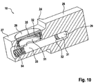
- Fig. 10 shows the design of the base body 24 according to a further embodiment.
- a large piston 29 is provided on each extension 27, 28.
- These large pistons 29 are also loaded via springs 32 and are located in hydraulic pressure chambers 31.
- Fig. 10 shows that a piston 29 is provided on each extension 27, 28 only on one side. Alternatively, however, two opposite pistons 29 could be used on each extension 27, 28.
- FIG. 10 shows Fig. 10 that 29 outlet openings 35 are provided in the piston. Oil can emerge from the hydraulic pressure pressure chambers 31 through these outlet openings 35.
- the outlet openings 35 each represent throttles in order to regulate the pressure in the hydraulic pressure chambers 31.
- the escaping oil serves to lubricate the surfaces between the clutch 10 and the two shafts 3, 7.
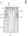
- Fig. 11 shows a further embodiment for the cross disc clutch. According to Fig. 11 there are a plurality of small pistons 29 arranged next to one another in both extensions 27, 28. Each piston 29 sits in its own hydraulic pressure chamber 31 and is designed as a spring 32 of its own Coil spring, loaded. In the exemplary embodiment shown, four pistons 29 are used per extension 27, 28.
- Fig. 12 shows the assembled state of the clutch assembly 1 according to a further embodiment, which is not part of the invention.
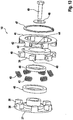
- Fig. 13 shows an exploded view of the associated clutch 10.
- the clutch 10 comprises a first ring 37, a second ring 39 and a compensating ring 41.
- the first ring 37 has an inner cone which is fitted on an outer cone on the first shaft 3. Furthermore, a clamping screw 49 is screwed into the first shaft 3 and fixes the first ring 37 on the first shaft 3 via a clamping disk 48.
- the second ring 39 is mounted on the second shaft 7 in a rotationally fixed manner by means of a cone clamping element 46 and a clamping sleeve 45.
- a locking ring 47 secures the axial position of the compensating ring 41 relative to the second ring 39.
- the first ring 37 has first claws 38.
- the second ring 39 has second claws 40.
- the first and second claws 38, 40 preferably extend in the axial direction.
- the compensating ring 41 has compensating claws 42.
- the compensating claws preferably extend in the radial direction 19.
- the first claws 38, second claws 40 and compensating claws 42 interlock. Viewed in the circumferential direction 18, there is a compensating claw 42 between a first claw 38 and a second claw 40.
- each of these pockets 44 there is a spring 43, in particular a spiral compression spring.
- the respective spring 43 is supported at one end in the pocket 44 and at the other end against a second claw 40.
- the spring 43 pushes the respective compensating claw 42 away from the second claw 40.
- the compensating claw 42 presses on one of the first claws 38, which in turn presses this first claw 38 against the next second claw 40.
- the invention relates to a clutch arrangement 1, comprising a first shaft 3, preferably a crankshaft of an internal combustion engine 2, a second shaft 7, preferably an armature shaft of an electrical machine 6, coaxial with the first shaft 3, and a clutch 10 for connecting the first shaft without play 3 with the second shaft 7, wherein a rotation axis 17 is defined according to the two coaxial shafts 3, 7, a circumferential direction 18 is defined around the rotation axis 17, and a radial direction 19 is defined perpendicular to the rotation axis 17, the coupling 10 at least one movement element 14, 31, 32, 43 and at least one coupling element 11, 29, 41 movable in the circumferential direction 18 and / or in the radial direction 19 with respect to the two shafts 3, 7, and wherein the movement element 14, 31, 32, 43 is designed to around the coupling element 11, 29, 41 in the circumferential direction 18 and / or radial direction 19 without play to the first and / or z wide shaft 3, 7 to press to compensate for a play in the circumferential direction 18
Landscapes
- Engineering & Computer Science (AREA)
- General Engineering & Computer Science (AREA)
- Mechanical Engineering (AREA)
- Mechanical Operated Clutches (AREA)
- Retarders (AREA)
- Shafts, Cranks, Connecting Bars, And Related Bearings (AREA)
- Transmission Devices (AREA)
Description
- Vorliegende Erfindung betrifft eine Kupplungsanordnung zum koaxialen Verbinden zweier Wellen. Insbesondere wird eine Kurbelwelle eines Verbrennungsmotors mit einer Ankerwelle einer elektrischen Maschine koaxial verbunden. Des Weiteren betrifft die Erfindung ein Verfahren zur Montage der Kupplungsanordnung.
- Der Stand der Technik kennt verschiedene Anordnungen zum Verbinden einer Verbrennungsmaschine mit einer elektrischen Maschine in einem Kraftfahrzeug. Im Stand der Technik werden üblicherweise Riementriebe verwendet, um die Kurbelwelle mit der Ankerwelle zu verbinden. Die Riemenscheiben sorgen dabei für einen Ausgleich der Drehmomentschwankungen und für eine spielfreie Kraftübertragung. Die Verwendung des Riementriebes und infolgedessen auch die nicht koaxiale Anordnung der elektrischen Maschine bzgl. des Verbrennungsmotors führen zu einer nicht platzsparenden Konstruktion. Des Weiteren ist der Riementrieb wartungsanfällig.
- Die
WO 2007/107138 A1 beschreibt eine Drehmomentübertragungseinrichtung mit einem Eingangsteil und einem Ausgangsteil, die jeweils mit einer drehbaren Welle verbindbar sind und über wenigstens ein Zwischenelement, das eine radiale Verlagerung der beiden Teile ermöglicht, antriebsmässig gekoppelt sind. Das Zwischenelement ist mittels wenigstens zwei, die radiale Verlagerung ermöglichende, radial elastischen Bereichen einerseits mit dem Eingangsteil und andererseits mit dem Ausgangsteil gekoppelt.
Es ist Aufgabe vorliegender Erfindung, eine Kupplungsanordnung zum koaxialen Verbinden zweier Wellen anzugeben, die bei kostengünstiger Herstellung und Montage wartungsarm und geräuscharm funktioniert. Des Weiteren ist es Aufgabe vorliegender Erfindung, ein entsprechendes Verfahren zur Montage der Kupplungsanordnung anzugeben. Zusätzlich hat die Verbindung die Aufgabe, Koaxialitätsfehler (Winkel- und Achsversatz) zwischen Verbrennungsmotor und elektrischer Maschine auszugleichen. - Die Aufgabe wird gelöst durch die Merkmale der unabhängigen Ansprüche. Die abhängigen Ansprüche haben vorteilhafte Weiterbildungen der Erfindung zum Gegenstand.
- Somit wird die Aufgabe gelöst durch eine Kupplungsanordnung umfassend eine erste Welle, eine zweite Welle und eine Kupplung. Die erste Welle ist insbesondere eine Kurbelwelle eines Verbrennungsmotors in einem Kraftfahrzeug. Die zweite Welle ist insbesondere eine Ankerwelle einer elektrischen Maschine. Die elektrische Maschine wird vorzugsweise als Hochvoltgenerator zum Erzeugen elektrischer Energie betrieben. Ferner kann die elektrische Maschine auch als Elektromotor zum Starten des Verbrennungsmotors verwendet werden. Das Gehäuse der elektrischen Maschine ist vorzugsweise direkt mit dem Kurbelwellengehäuse bzw. dem Gehäuse des Verbrennungsmotors verbunden. Die beiden Wellen sind koaxial angeordnet. Diese sehr kompakte und platzsparende Anordnung des Verbrennungsmotors und der elektrischen Maschine bedarf einer speziellen Ausbildung der Kupplung. Um ein geräuscharmes und wartungsarmes Funktionieren der Kupplung zu gewährleisten, ist eine spielfreie Kraftübertragung zwischen den beiden Wellen, insbesondere in beiden Drehrichtungen, zu gewährleisten. Die Kupplung umfasst deshalb zumindest ein Bewegungselement und ein Kupplungselement. Das Kupplungselement ist in Umfangsrichtung und/oder in Radialrichtung beweglich angeordnet. Das Bewegungselement sorgt dafür, dass das Kupplungselement in Umfangsrichtung oder Radialrichtung spielfrei an der jeweiligen Welle anliegt bzw. angedrückt wird. Durch das spielfreie Anliegen des Kupplungselementes an der jeweiligen Welle kann ein Drehmoment spielfrei zwischen den beiden Wellen übertragen werden.
- Insbesondere ist vorgesehen, dass das Bewegungselement eine Feder und/oder eine Hydraulikdruckkammer ist. Die Feder und/oder die Hydraulikdruckkammer ist in der Kupplung angeordnet und drückt das Kupplungselement gegen die erste oder zweite Welle, sodass das spielfreie Anliegen und somit auch die spielfreie Kraftübertragung möglich sind. Auch axiale Bewegungen sind möglich.
- Für die genaue Ausbildung der Kupplungsanordnung sind erfindungsgemäß drei Varianten vorgesehen:
Gemäß der ersten Variante umfasst die Kupplung eine erste Zahnwelle, eine zweite Zahnwelle und eine dritte Zahnwelle. Die drei Zahnwellen bilden Kupplungselemente. Die erste Zahnwelle ist von der zweiten Zahnwelle beabstandet. Zwischen der ersten Zahnwelle und der zweiten Zahnwelle befindet sich die dritte Zahnwelle. Die drei Zahnwellen sind koaxial entlang der Rotationsachse angeordnet. Die erste Zahnwelle ist über eine Torsionsfeder mit der zweiten Zahnwelle verbunden. Dementsprechend sind die erste Zahnwelle und die zweite Zahnwelle jeweils drehfest, beispielsweise über einen Mehrkant, mit der Torsionsfeder verbunden. Die Torsionsfeder bildet in dieser Variante das Bewegungselement. Die Torsionsfeder sorgt dafür, dass die erste Zahnwelle spielfrei an der ersten Welle anliegt und die zweite Zahnwelle spielfrei an der zweiten Welle anliegt; erreicht wird dies dadurch, dass der Kraftfluss der beiden Wellen über die dritte Zahnwelle geschlossen wird. - Insbesondere ist vorgesehen, dass die erste Welle eine erste Wellenverzahnung umfasst und die zweite Welle eine zweite Wellenverzahnung umfasst. Die beiden Wellenverzahnungen sind insbesondere Innenverzahnungen an der Kurbelwelle und an der Ankerwelle. Im montierten Zustand der Kupplungsanordnung steht die erste Wellenverzahnung sowohl mit der ersten Zahnwelle als auch mit der dritten Zahnwelle im Eingriff, die zweite Wellenverzahnung steht mit der zweiten Zahnwelle und gleichzeitig mit der dritten Zahnwelle im Eingriff.
- Um den Ausgleich der fertigungstechnisch bedingten Fehler bezüglich Achsvorsatz und Winkel zu schaffen, ist die Verzahnung flankenzentriert und an beiden Enden von Zahnwelle 3 ballig ausgeführt.
- Die dritte Zahnwelle ist vorzugsweise innen hohl ausgebildet. Dadurch kann die Torsionsfeder sich durch die dritte Zahnwelle hindurch erstrecken. An den beiden Enden der Torsionsfeder sitzen die erste Zahnwelle und die zweite Zahnwelle. Die dritte Zahnwelle ist vorzugsweise gegenüber der Torsionsfeder drehbar angeordnet.
- Die erste Zahnwelle und die zweite Zahnwelle sind bevorzugt gegeneinander verdreht, sodass die Torsionsfeder gespannt ist. Die erste Welle, insbesondere die erste Wellenverzahnung liegt, je nach Drehrichtung, entweder an der ersten Zahnwelle oder an der dritten Zahnwelle an. Genauso kann die zweite Wellenverzahnung entweder an der zweiten Zahnwelle oder an der dritten Zahnwelle anliegen. Die unterschiedlichen Drehrichtungen treten auf, je nachdem, ob die elektrische Maschine generatorisch oder motorisch betrieben wird. Dadurch, dass den Wellenverzahnungen jeweils die Zahnflanken der ersten Zahnwelle und der dritten Zahnwelle bzw. der zweiten Zahnwelle und der dritten Zahnwelle zur Verfügung stehen, ist eine spielfreie Kraftübertragung zwischen der Kurbelwelle und der Ankerwelle möglich.
- In der zweiten Variante ist die Kupplung als Kreuzscheibenkupplung ausgebildet. Die Kreuzscheibenkupplung wird auch als "Oldhamkupplung" bezeichnet. Hierzu umfasst die Kupplung einen Grundkörper. Der Grundkörper umfasst beidseitig jeweils einen Fortsatz. Der erste Fortsatz steckt in einer Nut der ersten Welle. Der zweite Fortsatz steckt in einer Nut der zweiten Welle. Die in den Nuten steckenden Fortsätze ermöglichen im begrenzten Umfang einen Ausgleich eines radialen und axialen Versatzes zwischen den beiden Wellen.
- In der zweiten Variante ist das Bewegungselement bevorzugt eine Feder und/oder eine Hydraulikdruckkammer. Das Kupplungselement ist als zumindest ein Kolben ausgebildet. Der Kolben ist im Grundkörper linear beweglich geführt. Die Feder und/oder die Hydraulikdruckkammer sorgen dafür, dass der Kolben vom Grundkörper weggedrückt wird. Dadurch liegt der Kolben in der Nut der jeweiligen Welle an und sorgt für eine spielfreie Kraftübertragung.
- Insbesondere ist vorgesehen, dass auf der der ersten Welle zugewandten Seite des Grundkörpers, also am ersten Fortsatz, zumindest ein Kolben vorgesehen ist und dass auf der der zweiten Welle zugewandten Seite, also am zweiten Fortsatz, ebenfalls zumindest ein Kolben angeordnet ist.
- In besonders bevorzugter Ausführung sind in beiden Fortsätzen des Grundkörpers jeweils mehrere Kolben angeordnet. Jeder Kolben ist zumindest durch eine Feder belastet und kann darüber hinaus mittels einer eigenen Hydraulikdruckkammer nach außen gedrückt werden.
- Entsprechende Hydraulikkanäle im Grundkörper sorgen für eine Druckversorgung der Hydraulikdruckkammern. Insbesondere wird hierzu der Hydraulikdruck aus der Schmiermittelversorgung des Verbrennungsmotors verwendet.
- Ein bevorzugtes Rückschlagventil in den Hydraulikkanälen sorgt für eine ausreichende Aufrechterhaltung des Drucks in den Hydraulikdruckkammern unterhalb der einzelnen Kolben. In den Kolben sind bevorzugt kleine Auslassöffnungen vorgesehen. Über diese kleinen Auslassöffnungen tritt Hydrauliköl aus den Hydraulikdruckkammern auf die Oberfläche der Kolben. Dies führt zu einem gedrosselten Ablassen des Drucks in den Hydraulikdruckkammern und gleichzeitig zu einer Schmierung der Gleitflächen zwischen der Kupplung und den beiden Wellen.
- Die Kraft der Federn bzw. die Kraft der Hydraulikdruckkammern muss nicht so groß sein, um die Kolben stets vom Grundkörper wegzudrücken. Es reicht aus, dass die Kolben zumindest bei einem Wechsel der Drehrichtung an den beiden Wellen anliegen. Mit steigendem Drehmoment werden die Kolben dann in den Grundkörper hineingedrückt. Dabei wird das Hydrauliköl aus den Hydraulikdruckkammern bevorzugt über die Auslassöffnungen nach außen gefördert.
- Gemäß einer dritten Variante, welche nicht Teil der Erfindung ist, ist die Kupplung als Klauenkupplung ausgebildet. Die Kupplung umfasst dabei einen drehfest an der ersten Welle angeordneten ersten Ring, einen drehfest an der zweiten Welle angeordneten zweiten Ring und einen zwischen den beiden Wellen angeordneten Ausgleichsring. Der Ausgleichsring stellt dabei das bewegliche Kupplungselement dar. Der erste Ring umfasst erste Klauen. Der zweite Ring umfasst zweite Klauen. Der Ausgleichsring umfasst Ausgleichsklauen. Der Ausgleichsring ist im begrenzten Umfang gegenüber den beiden Wellen beweglich. Die ersten Klauen, die zweiten Klauen und die Ausgleichsklauen greifen ineinander. Je nach Größe der Klauen, ist somit ein begrenzter Ausgleich eines radialen und axialen Versatzes möglich. Betrachtet man die Anordnung in Umfangsrichtung, so befindet sich jeweils eine Ausgleichsklaue zwischen einer ersten Klaue und einer zweiten Klaue. Zumindest zwischen einer zweiten Klaue und einer Ausgleichsklaue ist eine Feder, ausgebildet als Spiraldruckfeder oder Tellerfeder, angeordnet. Die Feder stützt sich mit einem Ende gegen eine zweite Klaue und mit dem anderen Ende gegen eine Ausgleichsklaue. Die Ausgleichsklaue wiederum drückt gegen eine erste Klaue, wodurch diese erste Klaue gegen eine nächste zweite Klaue gedrückt wird. Die Feder dient somit dazu, die zweiten Klauen gegen die ersten Klauen in Richtung des abgebenden Nutzmomentes zu drücken.
- Insbesondere sind Taschen in den Ausgleichsklauen vorgesehen, sodass die Federn teilweise in diesen Taschen angeordnet werden können. Bei einem Wechsel der Richtung des Moments werden die Federn soweit komprimiert, sodass sie vollständig in den Taschen sitzen. Dadurch liegen die Ausgleichsklauen auf den zweiten Klauen an.
- Zur Montage des zweiten Rings auf der zweiten Welle wird vorzugsweise ein Konusspannelement verwendet.
- Die erste Welle ist vorzugsweise konusförmig ausgebildet. Ein dazu passender Innenkonus ist vorzugsweise an dem ersten Ring ausgebildet. Zusätzlich zu dieser Konusverbindung wird bevorzugt eine Spanschraube und eine Spannscheibe verwendet. Die Spannschraube wird vorzugsweise stirnseitig in die erste Welle geschraubt, um so den ersten Ring auf der ersten Welle zu halten.
- Die Erfindung umfasst bevorzugt ein Steuergerät zum Steuern und/oder Regeln der elektrischen Maschine, wobei das Steuergerät dazu ausgebildet ist, die elektrische Maschine so anzusteuern, um Drehungleichförmigkeiten auszugleichen. Zum Beispiel in Abhängigkeit der Zylinderanzahl im Verbrennungsmotor entstehen Drehungleichförmigkeiten an der Kurbelwelle. Diese können durch eine entsprechende Ansteuerung der elektrischen Maschine ausgeglichen werden.
- Die Erfindung umfasst des Weiteren ein Verfahren zur Montage einer Kupplungsanordnung gemäß der oben beschriebenen ersten Variante. Dieses Verfahren umfasst die folgenden Schritte: (i) Spannen der Torsionsfeder durch Verdrehen der ersten Zahnwelle gegenüber der zweiten Zahnwelle, (ii) Einsetzen einer ersten Verdrehsicherung, die die erste Zahnwelle gegenüber der dritten Zahnwelle fixiert und einer zweiten Verdrehsicherung, die die zweite Zahnwelle gegenüber der dritten Zahnwelle fixiert, (iii) Montieren der ersten Zahnwelle an der ersten Welle und der zweiten Zahnwelle an der zweiten Welle, und (iv) Lösen der beiden Verdrehsicherungen.
- Die Unteransprüche und die vorteilhaften Ausgestaltungen der erfindungsgemäßen Kupplungsanordnung finden entsprechend vorteilhafte Anwendung für das erfindungsgemäße Verfahren.
- Insbesondere ist bevorzugt vorgesehen, dass das Lösen der beiden Verdrehsicherungen gleichzeitig mit dem Montieren der ersten und zweiten Zahnwelle an der ersten und zweiten Welle erfolgt. Dabei wird durch Einschieben der jeweiligen Zahnwelle in die Innenverzahnung an der Kurbelwelle oder Ankerwelle die Verdrehsicherung verschoben. Dadurch löst sich die Verdrehsicherung.
- Für die Verdrehsicherung gibt es zwei bevorzugte Möglichkeiten: Zum einen kann die Verdrehsicherung als eine Manschette ausgebildet sein. Zum anderen kann die Verdrehsicherung als Pins ausgebildet sein.
- Die Manschette wird nach dem Spannen der Torsionsfeder aufgeschoben, sodass eine Innenverzahnung an der Manschette gleichzeitig mit der ersten Zahnwelle und der dritten Zahnwelle bzw. mit der zweiten Zahnwelle und der dritten Zahnwelle in Eingriff steht. Beim Montieren der Kupplung an den beiden Wellen, werden die Manschetten bevorzugt nach innen geschoben. Die Manschetten sitzen nach dem Montieren bevorzugt vollständig auf der dritten Zahnwelle. Nach dem Montieren erfüllen die Manschetten keine weitere Funktion, verbleiben jedoch bevorzugt auf der dritten Zahnwelle.
- Alternativ zu den Manschetten können die Pins verwendet werden. Die Pins stecken stirnseitig in den Zahnwellen. Nach dem Spannen der Torsionsfeder sind die Pins so positioniert, dass sie die erste Zahnwelle bezüglich der dritten Zahnwelle bzw. die zweite Zahnwelle bezüglich der dritten Zahnwelle fixieren, sodass sich die Torsionsfeder nicht mehr entspannen kann. Beim Montieren der Kupplungsanordnung werden die Pins verschoben, insbesondere nach innen in die dritte Zahnwelle.
- Es ist auch möglich, an einer Seite der Kupplung eine Manschette als Verdrehsicherung zu verwende und auf der anderen Seite die Pins.
- Zum Spannen der Torsionsfeder ist insbesondere folgender Verfahrensablauf vorgesehen: Durch Verdrehen der ersten und/oder zweiten Zahnwelle wird die Torsionsfeder gespannt, bis eine gewünschte Federkraft gemessen wird. Für das exakte Einstellen der Federkraft ist es vorteilhaft, die Materialplastifizierung (ähnlich Dehnschrauben) zu nutzen. Die Federkraft bleibt so über einen weiten "Aufzugswinkel" nahezu konstant und wird hauptsächlich durch den Federdurchmesser bestimmt. Daraufhin erfolgt ein Weiterdrehen oder Zurückdrehen der ersten Zahnwelle und/oder zweiten Zahnwelle, bis die Verzahnung der drei Zahnwellen übereinstimmt, sodass die Manschette aufgeschoben werden kann. Bei Verwendung der Pins, wird soweit vor- oder zurückgedreht, bis die Löcher der Pins fluchten, und infolgedessen die Pins eingesetzt werden können.
- Weitere Einzelheiten, Merkmale und Vorteile der Erfindung ergeben sich aus der nachfolgenden Beschreibung und den Figuren. Es zeigen:
- Figur 1
- eine erfindungsgemäße Kupplungsanordnung gemäß einem ersten Ausführungsbeispiel,
- Figuren 2 und 3
- eine Kupplung der erfindungsgemäßen Kupplungsanordnung gemäß dem ersten Ausführungsbeispiel,
- Figuren 4 bis 6
- eine Kupplung der erfindungsgemäßen Kupplungsanordnung gemäß einem zweiten Ausführungsbeispiel,
- Figur 7
- die erfindungsgemäße Kupplungsanordnung gemäß einem dritten Ausführungsbeispiel,
- Figuren 8 und 9
- die Kupplung der erfindungsgemäßen Kupplungsanordnung gemäß dem dritten Ausführungsbeispiel,
- Figur 10
- die Kupplung der erfindungsgemäßen Kupplungsanordnung gemäß einem vierten Ausführungsbeispiel,
- Figur 11
- die Kupplung der erfindungsgemäßen Kupplungsanordnung gemäß einem fünften Ausführungsbeispiel,
- Figur 12
- die erfindungsgemäße Kupplungsanordnung gemäß einem sechsten Ausführungsbeispiel, und
- Figur 13
- eine Explosionsdarstellung der Kupplung der erfindungsgemäßen Kupplungsanordnung gemäß dem sechsten Ausführungsbeispiel.
- Im Folgenden werden anhand der
Figuren 1 bis 13 sechs Ausführungsbeispiele einer Kupplungsanordnung 1 beschrieben. Gleiche bzw. funktional gleiche Bauteile sind dabei mit denselben Bezugszeichen versehen. - Gemäß
Fig. 1 umfasst die Kupplungsanordnung eine erste Welle 3, ausgebildet als Kurbelwelle eines Verbrennungsmotors 2 in einem Kraftfahrzeug. Die erste Welle 3 ist in einem Motorgehäuse 4 angeordnet. In dem Motorgehäuse 4 ist die erste Welle 3 über zumindest ein Lager 5 gelagert. - Des Weiteren umfasst die Kupplungsanordnung 1 eine zweite Welle 7, ausgebildet als Ankerwelle einer elektrischen Maschine 6. Die elektrische Maschine 6 wir in erster Linie als Hochvoltgenerator betrieben. Ferner kann die elektrische Maschine 6 auch motorisch betrieben werden, um den Verbrennungsmotor 2 zu starten. Die elektrische Maschine 6 umfasst ein Generatorgehäuse 8. In diesem Generatorgehäuse 8 ist die zweite Welle 7 gelagert.
- Über eine nur schematisch dargestellte Verschraubung 9 ist das Generatorgehäuse 8 mit dem Motorgehäuse 4 fest verbunden. Die beiden Wellen 3, 7 sind koaxial angeordnet. Die Anordnung ist dabei möglichst platzsparend konstruiert. Für die koaxiale Verbindung der beiden Wellen 3, 7 ist eine Kupplung 10 vorgesehen. Die Kupplung 10 ragt in eine Innenverzahnung an der ersten Welle 3 und in eine Innenverzahnung an der zweiten Welle 7. Das Generatorgehäuse 8 ist so eng an dem Motorgehäuse 4 platziert, sodass die Kupplung 10 in Axialrichtung bis zum Lager 5 ragt.
- Entsprechend der Rotation der beiden Wellen 3, 7 und der Kupplung 10 ist eine Rotationsachse 17 definiert. Um die Rotationsachse 17 herum ist eine Umfangsrichtung 18 definiert. Senkrecht zur Rotationsachse 17 steht eine Radialrichtung 19.
- Der genaue Aufbau der Kupplung 10 ist in den
Figuren 2 und3 gezeigt.Fig. 3 zeigt dabei eine Schnittansicht. Die Kupplung 10 umfasst eine erste Zahnwelle 11, eine zweite Zahnwelle 12, eine dritte Zahnwelle 13 und eine Torsionsfeder 14. Die dritte Zahnwelle 13 ist entlang der Rotationsachse 17 zwischen der ersten Zahnwelle 11 und der zweiten Zahnwelle 12 angeordnet. Die Torsionsfeder 14 ist an ihren Enden über einen Mehrkant 20 mit der ersten Zahnwelle 11 und der zweiten Zahnwelle 12 drehfest verbunden. Die dritte Zahnwelle 13 ist innen hohl, sodass sich die Torsionsfeder 14 durch die dritte Zahnwelle 13 hindurch erstrecken kann. - Die
Figuren 2 und3 zeigen die Kupplung 10 in einem Zustand, bevor sie in den beiden Wellen 3, 7 montiert wird. Gemäß denFiguren 2 und3 stecken beidseitig auf der Kupplung 10 Verdrehsicherungen 15, ausgebildet als Manschetten. Vor dem Montieren der Kupplung 10, werden die erste Zahnwelle 11 und die zweite Zahnwelle 12 gegeneinander verdreht, sodass die Torsionsfeder 14 gespannt ist. Um diesen gespannten Zustand zu halten, wird beidseitig die Verdrehsicherung 15 aufgeschoben. Die Verdrehsicherungen 15 greifen dabei in die Verzahnungen der Zahnwellen 11, 12, 13 ein. Beim Montieren der Kupplung 10, werden die Verdrehsicherungen 15 nach innen, auf die dritte Zahnwelle 13 verschoben. Dadurch sind die erste Zahnwelle 11 und die zweite Zahnwelle 12 nicht mehr gegenüber der dritten Zahnwelle 13 fixiert und die Torsionsfeder 14 kann wirken, wodurch die abtreibende Flanke der Innenverzahnung der Kurbelwelle an die angetriebene Flanke von Zahnwelle 13 und abtreibende Flanke der Zahnwelle 13 an die anzutreibende Flanke der Innenverzahnung der Ankerwelle mit der Federkraft gedrückt wird. - Die beiden Verdrehsicherungen 15 können nach dem Montieren funktionslos auf der dritten Zahnwelle 13 verbleiben. Gemäß
Fig. 2 sind an den beiden Verdrehsicherungen 15 mehrere Nasen 16 ausgebildet. An der ersten Welle 3 und/oder an der zweiten Welle 7 müssen Vorrichtungen vorgesehen sein, die an diese Nasen 16 angreifen, um beim Montieren die Verdrehsicherungen 15 nach innen zu verschieben und die Haltekraft von der Vorspannung von den Manschetten an die Innenverzahnung zu übergeben. -
Figuren 4 bis 6 zeigen ein weiteres Ausführungsbeispiel, bei dem die Kupplung 10 die drei Zahnwellen 11, 12, 13 und die Torsionsfeder 14 umfasst.Fig. 4 zeigt eine Explosionsdarstellung der Kupplung 10. DieFiguren 5 und6 zeigen Schnittansichten der Kupplung 10 in verschiedenen Montagezuständen. - Im zweiten Ausführungsbeispiel sind die Verdrehsicherungen als Pins 21 ausgebildet. Nach dem Verdrehen der ersten Zahnwelle 11 und der zweiten Zahnwelle 12, zum Spannen der Torsionsfeder 14, werden Pins 21 eingeschoben, um die Torsionsfeder 14 auf Spannung zu halten. Dieser Zustand ist in
Fig. 5 dargestellt. - Bei der Montage der Kupplung 10 in die beiden Wellen 3, 7 werden Montagestifte 22 stirnseitig eingeschoben. Diese Montagestifte 22 schieben die Pins 21 weiter nach innen, in die dritte Zahnwelle 13. Dadurch löst sich die Verdrehsicherung und die Torsionsfeder 14 kann wirken.
- Zum Einschieben der Montagestifte 22 sind beidseitig stirnseitige Montageplatten 23 gezeigt. Diese Montageplatten 23 können auch Bestandteile der Wellen 3, 7 sein, sodass gleichzeitig mit dem Montieren der Kupplung 10 die Pins 21 gelöst werden.
- Die
Figuren 7 bis 11 zeigen Ausführungsbeispiele, bei denen die Kupplung 10 als Kreuzscheibenkupplung (auch: Oldhamkupplung) ausgebildet sind. -
Fig. 7 zeigt die Kupplungsanordnung 1 mit der Kupplung 10. Die Kupplung 10 umfasst einen Grundkörper 24. Der Grundkörper 24 weist an seinen beiden axialen Enden jeweils einen Fortsatz 27, 28 auf. Der erste Fortsatz 27 steckt in einer ersten Nut 25 in der ersten Welle 3. Der zweite Fortsatz 28 steckt in einer zweiten Nut 26 in der zweiten Welle 7. -
Fig. 8 zeigt den ersten Fortsatz 27 des Grundkörpers 24 im Detail. Der zweite Fortsatz 28 ist genauso, jedoch um 90° um die Rotationsachse 17 verdreht, aufgebaut. - Am ersten Fortsatz 27 gibt es zwei gegenüberliegende Flächen, die je nach Drehrichtung in der ersten Nut 24 anliegen, um Drehmoment zu übertragen. Auf beiden Flächen ist jeweils ein Kolben 29 vorgesehen. Der Kolben 29 stellt eine plane Fläche für die spielfreie Anlage dar.
- An der Innenseite der Kolben 29 sind jeweils vier Noppen 30 vorgesehen. Die Noppen 30 stecken jeweils in einer Hydraulikdruckkammer 31. In den Hydraulikdruckkammern 31 befindet sich jeweils eine Feder 32, ausgebildet als Tellerfeder. Die Federn 32 und der entsprechende Druck in den Hydraulikdruckkammern 31 drücken die Kolben 29 vom ersten Fortsatz 27 weg.
-
Fig. 9 zeigt in einer Schnittansicht Hydraulikkanäle 33 zur Druckversorgung der Hydraulikkammern 31. Ein Rückschlagventil 34 sorgt für einen ausreichenden Druckerhalt in den Hydraulikdruckkammern 31. Über das Rückschlagventil 34 wird vorzugsweise Hydrauliköl aus dem Verbrennungsmotor 2 in die Hydraulikkanäle 33 und somit in die Hydraulikdruckkammern 31 gefördert. -
Fig. 10 zeigt die Ausbildung des Grundkörpers 24 gemäß einem weiteren Ausführungsbeispiel. In diesem Ausführungsbeispiel ist an jedem Fortsatz 27, 28 jeweils ein großer Kolben 29 vorgesehen. Auch diese großen Kolben 29 sind über Federn 32 belastet und befinden sich in Hydraulikdruckkammern 31.Fig. 10 zeigt, dass an jedem Fortsatz 27, 28 jeweils nur auf einer Seite ein Kolben 29 vorgesehen ist. Alternativ dazu könnten jedoch an jedem Fortsatz 27, 28 jeweils zwei gegenüberliegende Kolben 29 verwendet werden. - Des Weiteren zeigt
Fig. 10 , dass in den Kolben 29 Auslassöffnungen 35 vorgesehen sind. Durch diese Auslassöffnungen 35 können Öl aus den Hydraulikdruckdruckkammern 31 nach außen treten. Die Auslassöffnungen 35 stellen jeweils Drosseln dar, um den Druck in den Hydraulikdruckkammern 31 zu regulieren. Gleichzeitig dient das austretende Öl zur Schmierung der Flächen zwischen der Kupplung 10 und den beiden Wellen 3, 7. -
Fig. 11 zeigt ein weiteres Ausführungsbeispiel für die Kreuzscheibenkupplung. GemäßFig. 11 gibt es in beiden Fortsätzen 27, 28 mehrere, nebeneinander angeordnete kleine Kolben 29. Jeder Kolben 29 sitzt in einer eigenen Hydraulikdruckkammer 31 und ist über eine eigene Feder 32, ausgebildet als Spiralfeder, belastet. Im gezeigten Ausführungsbeispiel werden pro Fortsatz 27, 28 vier Kolben 29 verwendet. - Überschüssige Öffnungen, die beim Bohren der Hydraulikkanäle 33 anfallen, sind über Verschlusskugeln 36 verschlossen.
-
Fig. 12 zeigt den montierten Zustand der Kupplungsanordnung1 gemäß einem weiteren Ausführungsbeispiel, welches nicht Teil der Erfindung ist.Fig. 13 zeigt eine Explosionsdarstellung der zugehörigen Kupplung 10. - Die Kupplung 10 umfasst einen ersten Ring 37, einen zweiten Ring 39 und einen Ausgleichsring 41. Der erste Ring 37 weist einen Innenkonus auf, der auf einem Außenkonus auf der ersten Welle 3 steckt. Des Weiteren ist in die erste Welle 3 eine Spannschraube 49 eingeschraubt, die über eine Spannscheibe 48 den ersten Ring 37 auf der ersten Welle 3 fixiert.
- Der zweite Ring 39 ist mittels eines Konusspannelementes 46 und einer Spannhülse 45 drehfest auf der zweiten Welle 7 montiert. Ein Sicherungsring 47 sichert die axiale Lage des Ausgleichsrings 41 gegenüber dem zweiten Ring 39.
- Der erste Ring 37 weist erste Klauen 38 auf. Der zweite Ring 39 weist zweite Klauen 40 auf. Die ersten und zweiten Klauen 38, 40 erstrecken sich vorzugsweise in Axialrichtung. Der Ausgleichsring 41 weist Ausgleichsklauen 42 auf. Die Ausgleichsklauen erstrecken sich bevorzugt in Radialrichtung 19.
- Die ersten Klauen 38, zweiten Klauen 40 und Ausgleichsklauen 42 greifen ineinander. In Umfangsrichtung 18 betrachtet befindet sich jeweils eine Ausgleichsklaue 42 zwischen einer ersten Klaue 38 und einer zweiten Klaue 40.
- An den Ausgleichsklauen 42 sind sich in Umfangsrichtung 18 öffnende Taschen 44 ausgebildet. In diesen Taschen 44 sitzt jeweils eine Feder 43, insbesondere Spiraldruckfeder. Die jeweilige Feder 43 stützt sich mit einem Ende in der Tasche 44 und mit dem anderen Ende gegen eine zweite Klaue 40 ab. Die Feder 43 drückt die jeweilige Ausgleichsklaue 42 von der zweiten Klaue 40 weg. Dadurch drückt die Ausgleichsklaue 42 auf eine der ersten Klauen 38, wodurch wiederum diese erste Klaue 38 gegen die nächste zweite Klaue 40 gedrückt wird. Dadurch ist ein spielfreies Anliegen der ersten Klaue 38 an der zweiten Klaue 40 und somit auch eine spielfreie Drehmomentübertragung möglich.
- Zusammenfassend betrifft die Erfindung eine Kupplungsanordnung 1, umfassend eine erste Welle 3, vorzugsweise eine Kurbelwelle eines Verbrennungsmotors 2, eine zur ersten Welle 3 koaxial angeordnete zweite Welle 7, vorzugsweise eine Ankerwelle einer elektrischen Maschine 6, und eine Kupplung 10 zum spielfreien Verbinden der ersten Welle 3 mit der zweiten Welle 7, wobei entsprechend der beiden koaxialen Wellen 3, 7 eine Rotationsachse 17 definiert ist, um die Rotationsachse 17 eine Umfangsrichtung 18 definiert ist, und senkrecht zur Rotationsachse 17 eine Radialrichtung 19 definiert ist, wobei die Kupplung 10 zumindest ein Bewegungselement 14, 31, 32, 43 und zumindest ein gegenüber den beiden Wellen 3, 7 in Umfangsrichtung 18 und/oder in Radialrichtung 19 bewegliches Kupplungselement 11, 29, 41 umfasst, und wobei das Bewegungselement 14, 31, 32, 43 dazu ausgebildet ist, um das Kupplungselement 11, 29, 41 in Umfangsrichtung 18 und/oder Radialrichtung 19 spielfreie an die erste und/oder zweite Welle 3, 7 anzudrücken, um ein Spiel in Umfangsrichtung 18 zwischen den beiden Wellen 3, 7, sowie fertigungstechnisch unumgängliche Toleranzen bezüglich Achs- und Winkelvorsatz von den beiden Wellen 3 und 7 auszugleichen. Ebenso wird ermöglicht, einen axialen Ausgleich während des Betriebs aufgrund von z.B. thermischer Ausdehnung zu schaffen.
-
- 1
- Kupplungsanordnung
- 2
- Verbrennungsmotor
- 3
- erste Welle (Kurbelwelle)
- 4
- Motorgehäuse
- 5
- Lager
- 6
- elektrische Maschine
- 7
- zweite Welle (Ankerwelle)
- 8
- Generatorgehäuse
- 9
- Verschraubung
- 10
- Kupplung
- 11
- erste Zahnwelle
- 12
- zweite Zahnwelle
- 13
- dritte Zahnwelle
- 14
- Torsionsfeder
- 15
- Verdrehsicherungen
- 16
- Nasen
- 17
- Rotationsachse
- 18
- Umfangsrichtung
- 19
- Radialrichtung
- 20
- Mehrkant
- 21
- Pins
- 22
- Montagestift
- 23
- Montageplatte
- 24
- Grundkörper
- 25
- erste Nut
- 26
- zweite Nut
- 27
- erster Fortsatz
- 28
- zweiter Fortsatz
- 29
- Kolben
- 30
- Noppen
- 31
- Hydraulikdruckkammern
- 32
- Federn
- 33
- Hydraulikkanäle
- 34
- Rückschlagventil
- 35
- Auslassöffnungen
- 36
- Verschlusskugeln
- 37
- erster Ring
- 38
- erste Klauen
- 39
- zweiter Ring
- 40
- zweite Klauen
- 41
- Ausgleichsring
- 42
- Ausgleichsklauen
- 43
- Federn
- 44
- Taschen
- 45
- Spanhülse
- 46
- Konusspannelement
- 47
- Sicherungsring
- 48
- Spannscheibe
- 49
- Spannschraube
Claims (12)
- Kupplungsanordnung (1) umfassend- eine erste Welle (3), vorzugsweise eine Kurbelwelle eines Verbrennungsmotors (2),- eine zur ersten Welle (3) koaxial angeordnete zweite Welle (7), vorzugsweise eine Ankerwelle einer elektrischen Maschine (6), und- eine Kupplung (10) zum spielfreien Verbinden der ersten Welle (3) mit der zweiten Welle (7),- wobei entsprechend der beiden koaxialen Wellen (3, 7) eine Rotationsachse (17) definiert ist, um die Rotationsachse (17) eine Umfangsrichtung (18) definiert ist, und senkrecht zur Rotationsachse (17) eine Radialrichtung (19) definiert ist,- wobei die Kupplung (10) zumindest ein Bewegungselement (14, 31, 32, 43) und zumindest ein gegenüber den beiden Wellen (3, 7) in Umfangsrichtung (18) und/oder in Radialrichtung (19) bewegliches Kupplungselement (11, 29, 41) umfasst, und- wobei das Bewegungselement (14, 31, 32, 43) dazu ausgebildet ist, um das Kupplungselement (11, 29, 41) in Umfangsrichtung (18) und/oder Radialrichtung (19) spielfreie an die erste und/oder zweite Welle (3, 7) anzudrücken, um ein Spiel in Umfangsrichtung (18) zwischen den beiden Wellen (3, 7) auszugleichen,dadurch gekennzeichnet, dass
die Kupplung (10) als Kupplungselemente eine erste Zahnwelle (11), eine zweite Zahnwelle (12) und eine zwischen der ersten Zahnwelle (11) und der zweiten Zahnwelle (12) angeordnete dritte Zahnwelle (13) umfasst, wobei die drei Zahnwellen (11-13) koaxial zur Rotationsachse (17) angeordnet sind, wobei die erste Zahnwelle (11) über eine Torsionsfeder (14) mit der zweiten Zahnwelle (12) verbunden ist. - Kupplungsanordnung nach Anspruch 1, dadurch gekennzeichnet, dass- die erste Welle (3) eine erste Wellenverzahnung umfasst, und- die zweite Welle (7) eine zweite Wellenverzahnung umfasst,- wobei die erste Wellenverzahnung mit der ersten Zahnwelle (11) und gleichzeitig mit der dritten Zahnwelle (13) im Eingriff steht, und- wobei die zweite Wellenverzahnung mit der zweiten Zahnwelle (12) und gleichzeitig mit der dritten Zahnwelle (13) im Eingriff steht.
- Kupplungsanordnung nach einem der Ansprüche 1 oder 2, dadurch gekennzeichnet, dass die erste Zahnwelle (11) und die zweite Zahnwelle (12) jeweils drehfest mit der Torsionsfeder (14) verbunden sind, und die dritte Zahnwelle (13) gegenüber der Torsionsfeder (14) drehbar angeordnet ist.
- Kupplungsanordnung nach einem der vorhergehenden Ansprüche, dadurch gekennzeichnet, dass die dritte Zahnwelle (13) innen hohl ist, und sich die Torsionsfeder (14) durch die dritte Zahnwelle (13) hindurch erstreckt.
- Kupplungsanordnung (1) nach einem der vorangehenden Ansprüchen umfassend- eine erste Welle (3), vorzugsweise eine Kurbelwelle eines Verbrennungsmotors (2),- eine zur ersten Welle (3) koaxial angeordnete zweite Welle (7), vorzugsweise eine Ankerwelle einer elektrischen Maschine (6), und- eine Kupplung (10) zum spielfreien Verbinden der ersten Welle (3) mit der zweiten Welle (7),- wobei entsprechend der beiden koaxialen Wellen (3, 7) eine Rotationsachse (17) definiert ist, um die Rotationsachse (17) eine Umfangsrichtung (18) definiert ist, und senkrecht zur Rotationsachse (17) eine Radialrichtung (19) definiert ist,- wobei die Kupplung (10) zumindest ein Bewegungselement (14, 31, 32, 43) und zumindest ein gegenüber den beiden Wellen (3, 7) in Umfangsrichtung (18) und/oder in Radialrichtung (19) bewegliches Kupplungselement (11, 29, 41) umfasst, und- wobei das Bewegungselement (14, 31, 32, 43) dazu ausgebildet ist, um das Kupplungselement (11, 29, 41) in Umfangsrichtung (18) und/oder Radialrichtung (19) spielfreie an die erste und/oder zweite Welle (3, 7) anzudrücken, um ein Spiel in Umfangsrichtung (18) zwischen den beiden Wellen (3, 7) auszugleichen,dadurch gekennzeichnet, dass
die Kupplung (10) als Kreuzscheibenkupplung ausgebildet ist und einen rotierenden Grundkörper (24) umfasst,- wobei die beiden Wellen (3, 7) jeweils eine Nut (25, 26) aufweisen, und der Grundkörper (24) mit den Fortsätzen (27, 28) in den Nuten (25, 26) steckt,- wobei zumindest ein Kupplungselement durch einen Kolben (29) gebildet ist, der im Grundkörper (24) in Radialrichtung (19) beweglich gelagert ist, und- wobei das Bewegungselement den Kolben (29) vom Grundkörper (24) weg drückt, sodass der Kolben (29) an der ersten oder zweiten Welle (3, 7) anliegt. - Kupplungsanordnung nach Anspruch 5, dadurch gekennzeichnet, dass auf der der ersten Welle (3) zugewandten Seite und auf der der zweiten Welle (7) zugewandten Seite des Grundkörpers (24) jeweils mehrere in Radialrichtung (19) bewegliche Kolben (29) angeordnet sind.
- Kupplungsanordnung nach einem der vorhergehenden Ansprüche, dadurch gekennzeichnet, dass das Bewegungselement eine Feder (14, 32, 43) und/oder eine Hydraulikdruckkammer (31) ist.
- Verfahren zur Montage einer Kupplungsanordnung (1) nach einem der Ansprüche 1 bis 4, umfassend die folgenden Schritte:- Spannen der Torsionsfeder (14) durch Verdrehen der ersten Zahnwelle (11) gegenüber der zweiten Zahnwelle (12),- Einsetzen einer ersten Verdrehsicherung (15), die die erste Zahnwelle (11) gegenüber der dritten Zahnwelle (13) fixiert und einer zweiten Verdrehsicherung (15), die die zweite Zahnwelle (12) gegenüber der dritten Zahnwelle (13) fixiert,- Montieren der ersten Zahnwelle (11) an der ersten Welle (3) und der zweiten Zahnwelle (12) an der zweiten Welle (7), und- Lösen der beiden Verdrehsicherungen (15).
- Verfahren nach Anspruch 8, dadurch gekennzeichnet, dass als erste Verdrehsicherung (15) eine erste Manschette aufgeschoben wird, die zum Fixieren gleichzeitig in die Verzahnung der ersten Zahnwelle (11) und der dritten Zahnwelle (13) eingreift, und/oder dass als zweite Verdrehsicherung (15) eine zweite Manschette aufgeschoben wird, die zum Fixieren gleichzeitig in die Verzahnung der zweiten Zahnwelle (12) und der dritten Zahnwelle (13) eingreift.
- Verfahren nach Anspruch 9, dadurch gekennzeichnet, dass die erste Manschette beim Montieren der ersten Zahnwelle (11) an der ersten Welle (3) vollständig auf die dritte Zahnwelle (13) aufgeschoben wird, und/oder dass die zweite Manschette beim Montieren der zweiten Zahnwelle (12) an der zweiten Welle (7) vollständig auf die dritte Zahnwelle (13) aufgeschoben wird.
- Verfahren nach einem der Ansprüche 8 bis 10, dadurch gekennzeichnet, dass als erste Verdrehsicherung (15) zumindest ein erster Pin (21) eingeschoben wird, der zum Fixieren gleichzeitig in der ersten Zahnwelle (11) und in der dritten Zahnwelle (13) steckt, und/oder dass als zweite Verdrehsicherung (15) zumindest ein zweiter Pin (21) eingeschoben wird, der zum Fixieren gleichzeitig in der zweiten Zahnwelle (12) und in der dritten Zahnwelle (13) steckt.
- Verfahren nach Anspruch 11, dadurch gekennzeichnet, dass der zumindest eine erste Pin (21) beim Montieren der ersten Zahnwelle (11) an der ersten Welle (3) vollständig in die dritte Zahnwelle (13) eingeschoben wird, und/oder dass der zumindest eine zweite Pin (21) beim Montieren der zweiten Zahnwelle (12) an der zweiten Welle (7) vollständig in die dritte Zahnwelle (13) eingeschoben wird.
Applications Claiming Priority (2)
| Application Number | Priority Date | Filing Date | Title |
|---|---|---|---|
| DE102013205531.5A DE102013205531A1 (de) | 2013-03-28 | 2013-03-28 | Kupplungsanordnung |
| PCT/EP2014/052706 WO2014154392A1 (de) | 2013-03-28 | 2014-02-12 | Kupplungsanordnung |
Publications (2)
| Publication Number | Publication Date |
|---|---|
| EP2978986A1 EP2978986A1 (de) | 2016-02-03 |
| EP2978986B1 true EP2978986B1 (de) | 2020-01-01 |
Family
ID=50073207
Family Applications (1)
| Application Number | Title | Priority Date | Filing Date |
|---|---|---|---|
| EP14703875.6A Active EP2978986B1 (de) | 2013-03-28 | 2014-02-12 | Kupplungsanordnung |
Country Status (5)
| Country | Link |
|---|---|
| US (1) | US9964157B2 (de) |
| EP (1) | EP2978986B1 (de) |
| CN (1) | CN104919200B (de) |
| DE (1) | DE102013205531A1 (de) |
| WO (1) | WO2014154392A1 (de) |
Families Citing this family (4)
| Publication number | Priority date | Publication date | Assignee | Title |
|---|---|---|---|---|
| RU2648535C1 (ru) * | 2016-11-28 | 2018-03-26 | Апетян Павел Мкртычевич | Гидро-кулачковая муфта |
| DE102018219826A1 (de) * | 2017-12-19 | 2019-06-19 | Heidelberger Druckmaschinen Ag | Druckkopf-Justagevorrichtung und Druckbalken |
| DE102018205866A1 (de) * | 2018-04-18 | 2019-10-24 | Robert Bosch Gmbh | Antriebswelle für eine Hochdruckpumpe, Hochdruckpumpe |
| CN116447242B (zh) * | 2023-03-20 | 2025-06-13 | 江苏玄博智能标识科技有限公司 | 一种金属切割设备的转轴连接件及传动机构 |
Family Cites Families (18)
| Publication number | Priority date | Publication date | Assignee | Title |
|---|---|---|---|---|
| US1337646A (en) * | 1919-07-24 | 1920-04-20 | George F Eckart | Flexible coupling |
| GB691281A (en) * | 1951-02-19 | 1953-05-06 | Transp Equipment Thorneycroft | Improvements in or relating to shaft couplings |
| US4332148A (en) * | 1980-06-04 | 1982-06-01 | General Motors Corporation | Cyclic phase-change coupling |
| DE3621187A1 (de) * | 1986-06-25 | 1988-01-21 | Hackforth Gmbh & Co Kg | Elastische wellenkupplung |
| US5355748A (en) | 1991-05-31 | 1994-10-18 | Ntn Corporation | Rotation transmitting device for an interaxle gearless differential |
| FR2682636B1 (fr) | 1991-10-21 | 1994-01-21 | Rapidex Sm | Ligne modulaire de fabrication d'emballages en carton. |
| ID16898A (id) * | 1996-05-14 | 1997-11-20 | Toyota Motor Co Ltd | Peralatan variabel tempo katup untuk internal mesin pembakar |
| US5984223A (en) * | 1998-06-05 | 1999-11-16 | Takata Corporation | Seat belt retractor and its spool |
| EP1148009A1 (de) * | 2000-04-20 | 2001-10-24 | Grapha-Holding Ag | Greiferwelle für einen Anleger |
| CN101405516A (zh) * | 2006-03-22 | 2009-04-08 | 卢克摩擦片和离合器两合公司 | 允许径向移位的转矩传递装置以及离合器盘 |
| US7658678B2 (en) * | 2007-01-17 | 2010-02-09 | The Gates Corporation | Pronged sleeve-type flexible shaft coupling |
| CN201113641Y (zh) * | 2007-09-17 | 2008-09-10 | 襄樊特种电机有限公司 | 一种客车用发电机 |
| CN201221573Y (zh) * | 2008-05-23 | 2009-04-15 | 袁志成 | 一种联轴器 |
| CN101858390A (zh) * | 2010-06-13 | 2010-10-13 | 太仓成铭液压机械有限公司 | 一种联轴器 |
| CN201794939U (zh) * | 2010-08-05 | 2011-04-13 | 叶笃孟 | 一种液压联轴器 |
| CN201891756U (zh) * | 2010-11-30 | 2011-07-06 | 广州能之原节能技术有限公司 | 一种伺服电机与油泵间的联接装置 |
| CN202125527U (zh) * | 2011-05-12 | 2012-01-25 | 株洲时代新材料科技股份有限公司 | 一种风力发电机组传动链柔性连接弹性元件 |
| DE102012223993A1 (de) * | 2012-01-27 | 2013-08-01 | Schaeffler Technologies AG & Co. KG | Drehmomentübertragungseinrichung mit Anbindung eines Wandlers nach Art einer flexiblen Hybridkopfanbindung sowie Versatzausgleichseinrichtung und Antriebsstrang |
-
2013
- 2013-03-28 DE DE102013205531.5A patent/DE102013205531A1/de not_active Withdrawn
-
2014
- 2014-02-12 EP EP14703875.6A patent/EP2978986B1/de active Active
- 2014-02-12 WO PCT/EP2014/052706 patent/WO2014154392A1/de not_active Ceased
- 2014-02-12 CN CN201480004995.7A patent/CN104919200B/zh active Active
-
2015
- 2015-09-25 US US14/865,470 patent/US9964157B2/en active Active
Non-Patent Citations (1)
| Title |
|---|
| None * |
Also Published As
| Publication number | Publication date |
|---|---|
| US20160010696A1 (en) | 2016-01-14 |
| EP2978986A1 (de) | 2016-02-03 |
| DE102013205531A1 (de) | 2014-10-02 |
| CN104919200A (zh) | 2015-09-16 |
| WO2014154392A1 (de) | 2014-10-02 |
| CN104919200B (zh) | 2019-02-05 |
| US9964157B2 (en) | 2018-05-08 |
Similar Documents
| Publication | Publication Date | Title |
|---|---|---|
| EP1552116B1 (de) | Elektrisch angetriebener nockenwellenversteller | |
| WO2004035997A1 (de) | Nockenwellenversteller mit elektrischem antrieb | |
| EP1515059A1 (de) | Einrichtung zur axialen Sicherung einer Kupplungseinrichtung an einer Drehdurchführung | |
| EP2060824B1 (de) | Torsionsschwingungsdämpferanordnung | |
| WO2018157879A1 (de) | Mehrfachkupplungseinrichtung und hybridmodul für ein kraftfahrzeug | |
| DE112015002170T5 (de) | Kopplungsverfahren für elektrische Versteller | |
| DE102013205531A1 (de) | Kupplungsanordnung | |
| DE102014200331B4 (de) | Ölpumpenantrieb mit schaltbarer Antriebsübersetzung | |
| DE102006028269A1 (de) | Überlagerungsgetriebe | |
| DE102016108876A1 (de) | Vorrichtung zur Betätigung eines Eingangsglieds | |
| DE102004041751A1 (de) | Nockenwellenversteller | |
| DE102011103495A1 (de) | Kupplungswelle,Aktor,Nockenwellenverstellgetriebe und Nockenwellensteller | |
| EP3504453A1 (de) | Doppelschlingfeder, rotationseinrichtung und zu aktuierendes system | |
| WO2009003686A1 (de) | Kupplungseinheit für nebenaggregate einer brennkraftmaschine | |
| DE10221625A1 (de) | Vorrichtung zur Kopplung einer Gehäuseanordnung einer Kopplungseinrichtung mit einer Rotoranordnung einer Elektromaschine | |
| DE102011008703A1 (de) | Vorrichtung zur trieblichen Verbindung | |
| DE102004058177B4 (de) | Zahnrad | |
| DE102007023617B4 (de) | Nockenwellenversteller | |
| DE102016214711A1 (de) | Doppelschlingfeder, Rotationseinrichtung und zu aktuierendes System | |
| DE3531848A1 (de) | Zahnrad-druckluftstarter | |
| EP1666769A1 (de) | Zahnrad | |
| WO2016184834A1 (de) | Nockenwellenverstelleinrichtung | |
| DE102021211648B4 (de) | Welle-Nabe-Verbindung | |
| DE102019117346B3 (de) | Elektromechanische Wasserpumpe mit Freilauf | |
| DE202011002172U1 (de) | Bolzenkupplung |
Legal Events
| Date | Code | Title | Description |
|---|---|---|---|
| PUAI | Public reference made under article 153(3) epc to a published international application that has entered the european phase |
Free format text: ORIGINAL CODE: 0009012 |
|
| 17P | Request for examination filed |
Effective date: 20150813 |
|
| AK | Designated contracting states |
Kind code of ref document: A1 Designated state(s): AL AT BE BG CH CY CZ DE DK EE ES FI FR GB GR HR HU IE IS IT LI LT LU LV MC MK MT NL NO PL PT RO RS SE SI SK SM TR |
|
| AX | Request for extension of the european patent |
Extension state: BA ME |
|
| DAX | Request for extension of the european patent (deleted) | ||
| STAA | Information on the status of an ep patent application or granted ep patent |
Free format text: STATUS: EXAMINATION IS IN PROGRESS |
|
| 17Q | First examination report despatched |
Effective date: 20181204 |
|
| GRAP | Despatch of communication of intention to grant a patent |
Free format text: ORIGINAL CODE: EPIDOSNIGR1 |
|
| STAA | Information on the status of an ep patent application or granted ep patent |
Free format text: STATUS: GRANT OF PATENT IS INTENDED |
|
| INTG | Intention to grant announced |
Effective date: 20190321 |
|
| GRAS | Grant fee paid |
Free format text: ORIGINAL CODE: EPIDOSNIGR3 |
|
| GRAJ | Information related to disapproval of communication of intention to grant by the applicant or resumption of examination proceedings by the epo deleted |
Free format text: ORIGINAL CODE: EPIDOSDIGR1 |
|
| GRAL | Information related to payment of fee for publishing/printing deleted |
Free format text: ORIGINAL CODE: EPIDOSDIGR3 |
|
| STAA | Information on the status of an ep patent application or granted ep patent |
Free format text: STATUS: EXAMINATION IS IN PROGRESS |
|
| INTC | Intention to grant announced (deleted) | ||
| GRAJ | Information related to disapproval of communication of intention to grant by the applicant or resumption of examination proceedings by the epo deleted |
Free format text: ORIGINAL CODE: EPIDOSDIGR1 |
|
| GRAP | Despatch of communication of intention to grant a patent |
Free format text: ORIGINAL CODE: EPIDOSNIGR1 |
|
| GRAP | Despatch of communication of intention to grant a patent |
Free format text: ORIGINAL CODE: EPIDOSNIGR1 |
|
| STAA | Information on the status of an ep patent application or granted ep patent |
Free format text: STATUS: GRANT OF PATENT IS INTENDED |
|
| INTG | Intention to grant announced |
Effective date: 20190906 |
|
| GRAA | (expected) grant |
Free format text: ORIGINAL CODE: 0009210 |
|
| STAA | Information on the status of an ep patent application or granted ep patent |
Free format text: STATUS: THE PATENT HAS BEEN GRANTED |
|
| AK | Designated contracting states |
Kind code of ref document: B1 Designated state(s): AL AT BE BG CH CY CZ DE DK EE ES FI FR GB GR HR HU IE IS IT LI LT LU LV MC MK MT NL NO PL PT RO RS SE SI SK SM TR |
|
| REG | Reference to a national code |
Ref country code: GB Ref legal event code: FG4D Free format text: NOT ENGLISH |
|
| REG | Reference to a national code |
Ref country code: CH Ref legal event code: EP Ref country code: AT Ref legal event code: REF Ref document number: 1220135 Country of ref document: AT Kind code of ref document: T Effective date: 20200115 |
|
| REG | Reference to a national code |
Ref country code: DE Ref legal event code: R096 Ref document number: 502014013372 Country of ref document: DE |
|
| REG | Reference to a national code |
Ref country code: IE Ref legal event code: FG4D Free format text: LANGUAGE OF EP DOCUMENT: GERMAN |
|
| REG | Reference to a national code |
Ref country code: NL Ref legal event code: MP Effective date: 20200101 |
|
| REG | Reference to a national code |
Ref country code: LT Ref legal event code: MG4D |
|
| PG25 | Lapsed in a contracting state [announced via postgrant information from national office to epo] |
Ref country code: NO Free format text: LAPSE BECAUSE OF FAILURE TO SUBMIT A TRANSLATION OF THE DESCRIPTION OR TO PAY THE FEE WITHIN THE PRESCRIBED TIME-LIMIT Effective date: 20200401 Ref country code: FI Free format text: LAPSE BECAUSE OF FAILURE TO SUBMIT A TRANSLATION OF THE DESCRIPTION OR TO PAY THE FEE WITHIN THE PRESCRIBED TIME-LIMIT Effective date: 20200101 Ref country code: RS Free format text: LAPSE BECAUSE OF FAILURE TO SUBMIT A TRANSLATION OF THE DESCRIPTION OR TO PAY THE FEE WITHIN THE PRESCRIBED TIME-LIMIT Effective date: 20200101 Ref country code: CZ Free format text: LAPSE BECAUSE OF FAILURE TO SUBMIT A TRANSLATION OF THE DESCRIPTION OR TO PAY THE FEE WITHIN THE PRESCRIBED TIME-LIMIT Effective date: 20200101 Ref country code: NL Free format text: LAPSE BECAUSE OF FAILURE TO SUBMIT A TRANSLATION OF THE DESCRIPTION OR TO PAY THE FEE WITHIN THE PRESCRIBED TIME-LIMIT Effective date: 20200101 Ref country code: LT Free format text: LAPSE BECAUSE OF FAILURE TO SUBMIT A TRANSLATION OF THE DESCRIPTION OR TO PAY THE FEE WITHIN THE PRESCRIBED TIME-LIMIT Effective date: 20200101 Ref country code: PT Free format text: LAPSE BECAUSE OF FAILURE TO SUBMIT A TRANSLATION OF THE DESCRIPTION OR TO PAY THE FEE WITHIN THE PRESCRIBED TIME-LIMIT Effective date: 20200527 |
|
| PG25 | Lapsed in a contracting state [announced via postgrant information from national office to epo] |
Ref country code: GR Free format text: LAPSE BECAUSE OF FAILURE TO SUBMIT A TRANSLATION OF THE DESCRIPTION OR TO PAY THE FEE WITHIN THE PRESCRIBED TIME-LIMIT Effective date: 20200402 Ref country code: BG Free format text: LAPSE BECAUSE OF FAILURE TO SUBMIT A TRANSLATION OF THE DESCRIPTION OR TO PAY THE FEE WITHIN THE PRESCRIBED TIME-LIMIT Effective date: 20200401 Ref country code: IS Free format text: LAPSE BECAUSE OF FAILURE TO SUBMIT A TRANSLATION OF THE DESCRIPTION OR TO PAY THE FEE WITHIN THE PRESCRIBED TIME-LIMIT Effective date: 20200501 Ref country code: SE Free format text: LAPSE BECAUSE OF FAILURE TO SUBMIT A TRANSLATION OF THE DESCRIPTION OR TO PAY THE FEE WITHIN THE PRESCRIBED TIME-LIMIT Effective date: 20200101 Ref country code: LV Free format text: LAPSE BECAUSE OF FAILURE TO SUBMIT A TRANSLATION OF THE DESCRIPTION OR TO PAY THE FEE WITHIN THE PRESCRIBED TIME-LIMIT Effective date: 20200101 Ref country code: HR Free format text: LAPSE BECAUSE OF FAILURE TO SUBMIT A TRANSLATION OF THE DESCRIPTION OR TO PAY THE FEE WITHIN THE PRESCRIBED TIME-LIMIT Effective date: 20200101 |
|
| REG | Reference to a national code |
Ref country code: CH Ref legal event code: PL |
|
| REG | Reference to a national code |
Ref country code: DE Ref legal event code: R097 Ref document number: 502014013372 Country of ref document: DE |
|
| REG | Reference to a national code |
Ref country code: BE Ref legal event code: MM Effective date: 20200229 |
|
| PG25 | Lapsed in a contracting state [announced via postgrant information from national office to epo] |
Ref country code: LU Free format text: LAPSE BECAUSE OF NON-PAYMENT OF DUE FEES Effective date: 20200212 Ref country code: SK Free format text: LAPSE BECAUSE OF FAILURE TO SUBMIT A TRANSLATION OF THE DESCRIPTION OR TO PAY THE FEE WITHIN THE PRESCRIBED TIME-LIMIT Effective date: 20200101 Ref country code: MC Free format text: LAPSE BECAUSE OF FAILURE TO SUBMIT A TRANSLATION OF THE DESCRIPTION OR TO PAY THE FEE WITHIN THE PRESCRIBED TIME-LIMIT Effective date: 20200101 Ref country code: EE Free format text: LAPSE BECAUSE OF FAILURE TO SUBMIT A TRANSLATION OF THE DESCRIPTION OR TO PAY THE FEE WITHIN THE PRESCRIBED TIME-LIMIT Effective date: 20200101 Ref country code: DK Free format text: LAPSE BECAUSE OF FAILURE TO SUBMIT A TRANSLATION OF THE DESCRIPTION OR TO PAY THE FEE WITHIN THE PRESCRIBED TIME-LIMIT Effective date: 20200101 Ref country code: SM Free format text: LAPSE BECAUSE OF FAILURE TO SUBMIT A TRANSLATION OF THE DESCRIPTION OR TO PAY THE FEE WITHIN THE PRESCRIBED TIME-LIMIT Effective date: 20200101 Ref country code: ES Free format text: LAPSE BECAUSE OF FAILURE TO SUBMIT A TRANSLATION OF THE DESCRIPTION OR TO PAY THE FEE WITHIN THE PRESCRIBED TIME-LIMIT Effective date: 20200101 Ref country code: RO Free format text: LAPSE BECAUSE OF FAILURE TO SUBMIT A TRANSLATION OF THE DESCRIPTION OR TO PAY THE FEE WITHIN THE PRESCRIBED TIME-LIMIT Effective date: 20200101 |
|
| PLBE | No opposition filed within time limit |
Free format text: ORIGINAL CODE: 0009261 |
|
| STAA | Information on the status of an ep patent application or granted ep patent |
Free format text: STATUS: NO OPPOSITION FILED WITHIN TIME LIMIT |
|
| PG25 | Lapsed in a contracting state [announced via postgrant information from national office to epo] |
Ref country code: CH Free format text: LAPSE BECAUSE OF NON-PAYMENT OF DUE FEES Effective date: 20200229 Ref country code: LI Free format text: LAPSE BECAUSE OF NON-PAYMENT OF DUE FEES Effective date: 20200229 |
|
| 26N | No opposition filed |
Effective date: 20201002 |
|
| PG25 | Lapsed in a contracting state [announced via postgrant information from national office to epo] |
Ref country code: IE Free format text: LAPSE BECAUSE OF NON-PAYMENT OF DUE FEES Effective date: 20200212 Ref country code: IT Free format text: LAPSE BECAUSE OF FAILURE TO SUBMIT A TRANSLATION OF THE DESCRIPTION OR TO PAY THE FEE WITHIN THE PRESCRIBED TIME-LIMIT Effective date: 20200101 |
|
| PG25 | Lapsed in a contracting state [announced via postgrant information from national office to epo] |
Ref country code: PL Free format text: LAPSE BECAUSE OF FAILURE TO SUBMIT A TRANSLATION OF THE DESCRIPTION OR TO PAY THE FEE WITHIN THE PRESCRIBED TIME-LIMIT Effective date: 20200101 Ref country code: SI Free format text: LAPSE BECAUSE OF FAILURE TO SUBMIT A TRANSLATION OF THE DESCRIPTION OR TO PAY THE FEE WITHIN THE PRESCRIBED TIME-LIMIT Effective date: 20200101 Ref country code: BE Free format text: LAPSE BECAUSE OF NON-PAYMENT OF DUE FEES Effective date: 20200229 |
|
| REG | Reference to a national code |
Ref country code: AT Ref legal event code: MM01 Ref document number: 1220135 Country of ref document: AT Kind code of ref document: T Effective date: 20200212 |
|
| PG25 | Lapsed in a contracting state [announced via postgrant information from national office to epo] |
Ref country code: AT Free format text: LAPSE BECAUSE OF NON-PAYMENT OF DUE FEES Effective date: 20200212 |
|
| PG25 | Lapsed in a contracting state [announced via postgrant information from national office to epo] |
Ref country code: TR Free format text: LAPSE BECAUSE OF FAILURE TO SUBMIT A TRANSLATION OF THE DESCRIPTION OR TO PAY THE FEE WITHIN THE PRESCRIBED TIME-LIMIT Effective date: 20200101 Ref country code: MT Free format text: LAPSE BECAUSE OF FAILURE TO SUBMIT A TRANSLATION OF THE DESCRIPTION OR TO PAY THE FEE WITHIN THE PRESCRIBED TIME-LIMIT Effective date: 20200101 Ref country code: CY Free format text: LAPSE BECAUSE OF FAILURE TO SUBMIT A TRANSLATION OF THE DESCRIPTION OR TO PAY THE FEE WITHIN THE PRESCRIBED TIME-LIMIT Effective date: 20200101 |
|
| PG25 | Lapsed in a contracting state [announced via postgrant information from national office to epo] |
Ref country code: MK Free format text: LAPSE BECAUSE OF FAILURE TO SUBMIT A TRANSLATION OF THE DESCRIPTION OR TO PAY THE FEE WITHIN THE PRESCRIBED TIME-LIMIT Effective date: 20200101 Ref country code: AL Free format text: LAPSE BECAUSE OF FAILURE TO SUBMIT A TRANSLATION OF THE DESCRIPTION OR TO PAY THE FEE WITHIN THE PRESCRIBED TIME-LIMIT Effective date: 20200101 |
|
| P01 | Opt-out of the competence of the unified patent court (upc) registered |
Effective date: 20230502 |
|
| PGFP | Annual fee paid to national office [announced via postgrant information from national office to epo] |
Ref country code: GB Payment date: 20260219 Year of fee payment: 13 |
|
| PGFP | Annual fee paid to national office [announced via postgrant information from national office to epo] |
Ref country code: DE Payment date: 20260210 Year of fee payment: 13 |
|
| PGFP | Annual fee paid to national office [announced via postgrant information from national office to epo] |
Ref country code: FR Payment date: 20260223 Year of fee payment: 13 |