EP2978986B1 - Système d'embrayage - Google Patents
Système d'embrayage Download PDFInfo
- Publication number
- EP2978986B1 EP2978986B1 EP14703875.6A EP14703875A EP2978986B1 EP 2978986 B1 EP2978986 B1 EP 2978986B1 EP 14703875 A EP14703875 A EP 14703875A EP 2978986 B1 EP2978986 B1 EP 2978986B1
- Authority
- EP
- European Patent Office
- Prior art keywords
- shaft
- splined shaft
- coupling
- splined
- shafts
- Prior art date
- Legal status (The legal status is an assumption and is not a legal conclusion. Google has not performed a legal analysis and makes no representation as to the accuracy of the status listed.)
- Active
Links
Images





Classifications
-
- F—MECHANICAL ENGINEERING; LIGHTING; HEATING; WEAPONS; BLASTING
- F16—ENGINEERING ELEMENTS AND UNITS; GENERAL MEASURES FOR PRODUCING AND MAINTAINING EFFECTIVE FUNCTIONING OF MACHINES OR INSTALLATIONS; THERMAL INSULATION IN GENERAL
- F16D—COUPLINGS FOR TRANSMITTING ROTATION; CLUTCHES; BRAKES
- F16D3/00—Yielding couplings, i.e. with means permitting movement between the connected parts during the drive
- F16D3/02—Yielding couplings, i.e. with means permitting movement between the connected parts during the drive adapted to specific functions
- F16D3/04—Yielding couplings, i.e. with means permitting movement between the connected parts during the drive adapted to specific functions specially adapted to allow radial displacement, e.g. Oldham couplings
-
- F—MECHANICAL ENGINEERING; LIGHTING; HEATING; WEAPONS; BLASTING
- F16—ENGINEERING ELEMENTS AND UNITS; GENERAL MEASURES FOR PRODUCING AND MAINTAINING EFFECTIVE FUNCTIONING OF MACHINES OR INSTALLATIONS; THERMAL INSULATION IN GENERAL
- F16D—COUPLINGS FOR TRANSMITTING ROTATION; CLUTCHES; BRAKES
- F16D1/00—Couplings for rigidly connecting two coaxial shafts or other movable machine elements
- F16D1/02—Couplings for rigidly connecting two coaxial shafts or other movable machine elements for connecting two abutting shafts or the like
-
- F—MECHANICAL ENGINEERING; LIGHTING; HEATING; WEAPONS; BLASTING
- F16—ENGINEERING ELEMENTS AND UNITS; GENERAL MEASURES FOR PRODUCING AND MAINTAINING EFFECTIVE FUNCTIONING OF MACHINES OR INSTALLATIONS; THERMAL INSULATION IN GENERAL
- F16D—COUPLINGS FOR TRANSMITTING ROTATION; CLUTCHES; BRAKES
- F16D3/00—Yielding couplings, i.e. with means permitting movement between the connected parts during the drive
- F16D3/02—Yielding couplings, i.e. with means permitting movement between the connected parts during the drive adapted to specific functions
- F16D3/10—Couplings with means for varying the angular relationship of two coaxial shafts during motion
-
- Y—GENERAL TAGGING OF NEW TECHNOLOGICAL DEVELOPMENTS; GENERAL TAGGING OF CROSS-SECTIONAL TECHNOLOGIES SPANNING OVER SEVERAL SECTIONS OF THE IPC; TECHNICAL SUBJECTS COVERED BY FORMER USPC CROSS-REFERENCE ART COLLECTIONS [XRACs] AND DIGESTS
- Y10—TECHNICAL SUBJECTS COVERED BY FORMER USPC
- Y10T—TECHNICAL SUBJECTS COVERED BY FORMER US CLASSIFICATION
- Y10T29/00—Metal working
- Y10T29/49—Method of mechanical manufacture
- Y10T29/49826—Assembling or joining
- Y10T29/49863—Assembling or joining with prestressing of part
- Y10T29/49874—Prestressing rod, filament or strand
-
- Y—GENERAL TAGGING OF NEW TECHNOLOGICAL DEVELOPMENTS; GENERAL TAGGING OF CROSS-SECTIONAL TECHNOLOGIES SPANNING OVER SEVERAL SECTIONS OF THE IPC; TECHNICAL SUBJECTS COVERED BY FORMER USPC CROSS-REFERENCE ART COLLECTIONS [XRACs] AND DIGESTS
- Y10—TECHNICAL SUBJECTS COVERED BY FORMER USPC
- Y10T—TECHNICAL SUBJECTS COVERED BY FORMER US CLASSIFICATION
- Y10T403/00—Joints and connections
- Y10T403/70—Interfitted members
- Y10T403/7026—Longitudinally splined or fluted rod
- Y10T403/7032—Longitudinally splined or fluted rod including a means, e.g., spring biased portion, for misalignment correction
Definitions
- the present invention relates to a clutch arrangement for coaxially connecting two shafts.
- a crankshaft of an internal combustion engine is coaxially connected to an armature shaft of an electrical machine.
- the invention relates to a method for assembling the clutch arrangement.
- the prior art knows various arrangements for connecting an internal combustion engine to an electrical machine in a motor vehicle.
- Belt drives are usually used in the prior art to connect the crankshaft to the armature shaft.
- the belt pulleys compensate for the torque fluctuations and for a play-free power transmission.
- the use of the belt drive and consequently also the non-coaxial arrangement of the electrical machine with respect to the internal combustion engine lead to a construction which does not save space.
- the belt drive is also prone to maintenance.
- the WO 2007/107138 A1 describes a torque transmission device with an input part and an output part, each of which can be connected to a rotatable shaft and is coupled in terms of drive by at least one intermediate element, which enables a radial displacement of the two parts.
- the intermediate element is coupled on the one hand to the input part and on the other hand to the output part by means of at least two radially elastic regions which enable radial displacement.
- the connection has the task Compensate for coaxiality errors (angular and axial misalignment) between the internal combustion engine and the electrical machine.
- a clutch arrangement comprising a first shaft, a second shaft and a clutch.
- the first shaft is in particular a crankshaft of an internal combustion engine in a motor vehicle.
- the second shaft is in particular an armature shaft of an electrical machine.
- the electrical machine is preferably operated as a high-voltage generator for generating electrical energy.
- the electrical machine can also be used as an electric motor for starting the internal combustion engine.
- the housing of the electrical machine is preferably connected directly to the crankshaft housing or the housing of the internal combustion engine.
- the two shafts are arranged coaxially. This very compact and space-saving arrangement of the internal combustion engine and the electrical machine requires a special coupling design.
- the clutch therefore comprises at least one moving element and one coupling element.
- the coupling element is arranged to be movable in the circumferential direction and / or in the radial direction.
- the movement element ensures that the coupling element rests or is pressed against the respective shaft without play in the circumferential direction or radial direction. Due to the play-free contact of the coupling element on the respective shaft, a torque can be transmitted without play between the two shafts.
- the movement element is a spring and / or a hydraulic pressure chamber.
- the spring and / or the hydraulic pressure chamber is arranged in the clutch and presses the clutch element against the first or second shaft, so that the play-free contact and thus the play-free power transmission are possible. Axial movements are also possible.
- the clutch comprises a first toothed shaft, a second toothed shaft and a third toothed shaft.
- the three splines form coupling elements.
- the first spline is spaced from the second spline.
- the third toothed shaft is located between the first toothed shaft and the second toothed shaft.
- the three splined shafts are arranged coaxially along the axis of rotation.
- the first toothed shaft is connected to the second toothed shaft via a torsion spring. Accordingly, the first toothed shaft and the second toothed shaft are each connected to the torsion spring in a rotationally fixed manner, for example via a polygon.
- the torsion spring forms the movement element.
- the torsion spring ensures that the first toothed shaft lies against the first shaft without play and the second toothed shaft lies against the second shaft without play; This is achieved by closing the power flow of the two shafts via the third splined shaft.
- the first shaft comprises a first shaft toothing and the second shaft comprises a second shaft toothing.
- the two shaft gears are in particular internal gears on the crankshaft and on the armature shaft.
- the first shaft toothing engages both the first toothed shaft and the third toothed shaft
- the second shaft toothing is engaged with the second toothed shaft and simultaneously with the third toothed shaft.
- the toothing is flank-centered and spherical at both ends of the toothed shaft 3.
- the third toothed shaft is preferably hollow on the inside.
- the torsion spring can extend through the third toothed shaft.
- the first splined shaft and the second splined shaft are located at the two ends of the torsion spring.
- the third toothed shaft is preferably rotatably arranged with respect to the torsion spring.
- the first toothed shaft and the second toothed shaft are preferably rotated relative to one another so that the torsion spring is tensioned.
- the first wave in particular Depending on the direction of rotation, the first shaft toothing lies either on the first spline or on the third spline.
- the second shaft toothing can rest either on the second toothed shaft or on the third toothed shaft.
- the different directions of rotation occur depending on whether the electrical machine is operated as a generator or a motor. Due to the fact that the tooth flanks of the first toothed shaft and the third toothed shaft or the second toothed shaft and the third toothed shaft are available to the shaft toothings, a play-free power transmission between the crankshaft and the armature shaft is possible.
- the clutch is designed as a cross disc clutch.
- the cross disc clutch is also referred to as the "Oldham clutch”.
- the coupling comprises a basic body.
- the base body comprises an extension on each side.
- the first extension is in a groove of the first shaft.
- the second extension is in a groove of the second shaft.
- the extensions stuck in the grooves make it possible to compensate for a radial and axial offset between the two shafts to a limited extent.
- the movement element is preferably a spring and / or a hydraulic pressure chamber.
- the coupling element is designed as at least one piston.
- the piston is guided in a linearly movable manner in the base body.
- the spring and / or the hydraulic pressure chamber ensure that the piston is pushed away from the base body. As a result, the piston rests in the groove of the respective shaft and ensures power transmission without play.
- At least one piston is provided on the side of the base body facing the first shaft, ie on the first extension, and that at least one piston is also arranged on the side facing the second shaft, ie on the second extension.
- a plurality of pistons are arranged in each of the two extensions of the base body.
- Each piston is loaded by at least one spring and can also be pressed outwards using its own hydraulic pressure chamber.
- Corresponding hydraulic channels in the base body ensure that the hydraulic pressure chambers are supplied with pressure.
- the Hydraulic pressure from the lubricant supply to the internal combustion engine is used.
- a preferred check valve in the hydraulic channels ensures sufficient maintenance of the pressure in the hydraulic pressure chambers below the individual pistons.
- Small outlet openings are preferably provided in the pistons. Hydraulic oil emerges from the hydraulic pressure chambers onto the surface of the pistons via these small outlet openings. This leads to a throttled release of the pressure in the hydraulic pressure chambers and at the same time to lubrication of the sliding surfaces between the clutch and the two shafts.
- the force of the springs or the force of the hydraulic pressure chambers need not be so great that the pistons are always pushed away from the base body. It is sufficient that the pistons rest against the two shafts at least when the direction of rotation changes. With increasing torque, the pistons are then pressed into the base body.
- the hydraulic oil is preferably conveyed out of the hydraulic pressure chambers through the outlet openings.
- the clutch is designed as a dog clutch.
- the clutch in this case comprises a first ring arranged in a rotationally fixed manner on the first shaft, a second ring arranged in a rotationally fixed manner on the second shaft and a compensating ring arranged between the two shafts.
- the compensating ring represents the movable coupling element.
- the first ring comprises first claws.
- the second ring includes second claws.
- the compensation ring includes compensation claws.
- the compensating ring is movable to a limited extent in relation to the two shafts.
- the first claws, the second claws and the compensating claws interlock. Depending on the size of the claws, limited compensation of radial and axial misalignment is possible.
- a compensating claw between a first claw and a second claw.
- a spring designed as a spiral compression spring or plate spring, is arranged.
- the spring is supported at one end against a second claw and at the other end against a compensating claw.
- the compensating claw in turn presses against a first claw, causing this first Claw is pressed against a next second claw.
- the spring thus serves to press the second claws against the first claws in the direction of the output useful torque.
- pockets are provided in the compensating claws, so that the springs can be partially arranged in these pockets.
- the springs When changing the direction of the moment, the springs are compressed so that they sit completely in the pockets. As a result, the compensating claws rest on the second claws.
- a cone clamping element is preferably used to mount the second ring on the second shaft.
- the first shaft is preferably conical.
- a matching inner cone is preferably formed on the first ring.
- a clamping screw and a clamping washer are preferably used.
- the clamping screw is preferably screwed into the first shaft on the end face in order to hold the first ring on the first shaft.
- the invention preferably comprises a control device for controlling and / or regulating the electrical machine, the control device being designed to control the electrical machine in order to compensate for rotational irregularities. For example, depending on the number of cylinders in the internal combustion engine, rotational irregularities occur on the crankshaft. These can be compensated for by controlling the electrical machine accordingly.
- the invention further comprises a method for assembling a clutch arrangement according to the first variant described above.
- This method comprises the following steps: (i) tensioning the torsion spring by rotating the first toothed shaft with respect to the second toothed shaft, (ii) inserting a first anti-twist device which fixes the first toothed shaft with respect to the third toothed shaft and a second anti-twist device with the second toothed shaft the third spline fixed, (iii) mounting the first spline on the first shaft and the second spline on the second shaft, and (iv) releasing the two anti-rotation devices.
- the two anti-rotation locks are released simultaneously with the mounting of the first and second toothed shafts on the first and second shafts.
- the anti-rotation device is shifted by inserting the respective splined shaft into the internal toothing on the crankshaft or armature shaft. This releases the anti-rotation lock.
- the anti-rotation device can be designed as a sleeve.
- the anti-rotation device can be designed as pins.
- the cuff is pushed on after tensioning the torsion spring, so that an internal toothing on the cuff simultaneously engages with the first spline and the third spline or with the second spline and the third spline.
- the sleeves are preferably pushed inwards. After assembly, the sleeves preferably sit completely on the third splined shaft. After assembly, the sleeves have no other function, but preferably remain on the third spline.
- the pins can be used as an alternative to the cuffs.
- the pins are inserted into the splines on the face. After tensioning the torsion spring, the pins are positioned so that they fix the first spline with respect to the third spline or the second spline with respect to the third spline, so that the torsion spring can no longer relax.
- the pins are shifted, in particular into the third splined shaft.
- the following procedure is provided for tensioning the torsion spring:
- the torsion spring is tensioned until a desired spring force is measured.
- the spring force remains almost constant over a wide "winding angle" and is mainly determined by the spring diameter.
- the first toothed shaft and / or second toothed shaft is then rotated further or turned back until the teeth of the three toothed shafts match, so that the sleeve can be pushed on.
- the pins turn back and forth until the holes of the pins are aligned, and as a result the pins can be inserted.
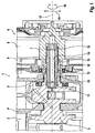
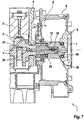
- the clutch arrangement comprises a first shaft 3, designed as a crankshaft of an internal combustion engine 2 in a motor vehicle.
- the first shaft 3 is arranged in a motor housing 4.
- the first shaft 3 is supported in the motor housing 4 via at least one bearing 5.
- the clutch arrangement 1 comprises a second shaft 7, designed as an armature shaft of an electrical machine 6.
- the electrical machine 6 is operated primarily as a high-voltage generator.
- the electrical machine 6 can also be operated by a motor in order to start the internal combustion engine 2.
- the electrical machine 6 comprises a generator housing 8.
- the second shaft 7 is mounted in this generator housing 8.
- the generator housing 8 is firmly connected to the motor housing 4 via a screw connection 9, which is only shown schematically.
- the two shafts 3, 7 are arranged coaxially. The arrangement is constructed as space-saving as possible.
- a coupling 10 is provided for the coaxial connection of the two shafts 3, 7.
- the clutch 10 projects into an internal toothing on the first shaft 3 and into an internal toothing on the second shaft 7.
- the generator housing 8 is placed so close to the motor housing 4 that the coupling 10 projects in the axial direction up to the bearing 5.
- An axis of rotation 17 is defined in accordance with the rotation of the two shafts 3, 7 and the clutch 10.
- a circumferential direction 18 is defined around the axis of rotation 17.
- a radial direction 19 is perpendicular to the axis of rotation 17.
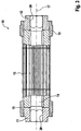
- the exact structure of the clutch 10 is in the Figures 2 and 3 shown.
- Fig. 3 shows a sectional view.
- the clutch 10 comprises a first toothed shaft 11, a second toothed shaft 12, a third toothed shaft 13 and a torsion spring 14.
- the third toothed shaft 13 is arranged along the axis of rotation 17 between the first toothed shaft 11 and the second toothed shaft 12.
- the torsion spring 14 is connected at its ends via a polygon 20 to the first toothed shaft 11 and the second toothed shaft 12 in a rotationally fixed manner.
- the third toothed shaft 13 is hollow on the inside, so that the torsion spring 14 can extend through the third toothed shaft 13.
- the Figures 2 and 3 show the clutch 10 in a state before it is mounted in the two shafts 3, 7.
- the Figures 2 and 3 are on both sides of the coupling 10 anti-rotation devices 15, designed as sleeves.
- the first toothed shaft 11 and the second toothed shaft 12 are rotated relative to one another, so that the torsion spring 14 is tensioned.
- the anti-rotation device 15 is pushed on both sides.
- the anti-rotation devices 15 engage in the toothing of the toothed shafts 11, 12, 13.
- the anti-rotation devices 15 are shifted inwards onto the third toothed shaft 13.
- the first toothed shaft 11 and the second toothed shaft 12 are no longer fixed relative to the third toothed shaft 13 and the torsion spring 14 can act, as a result of which the driven flank of the internal toothing of the crankshaft on the driven flank of toothed shaft 13 and the driven flank of the toothed shaft 13 on the one to be driven Flank of the internal toothing of the armature shaft is pressed with the spring force.
- the two anti-rotation locks 15 can remain without function on the third toothed shaft 13 after assembly.
- a plurality of lugs 16 are formed on the two anti-rotation devices 15. Devices must be provided on the first shaft 3 and / or on the second shaft 7 which engage these lugs 16 in order to adjust the anti-rotation locks 15 during assembly shift inside and transfer the holding force from the preload from the sleeves to the internal teeth.
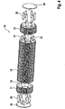
- Figures 4 to 6 show a further embodiment in which the clutch 10 comprises the three toothed shafts 11, 12, 13 and the torsion spring 14.
- Fig. 4 shows an exploded view of the clutch 10.
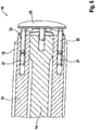
- Die Figures 5 and 6 show sectional views of the coupling 10 in different assembly states.
- the anti-rotation devices are designed as pins 21. After the first toothed shaft 11 and the second toothed shaft 12 have been rotated to tension the torsion spring 14, pins 21 are inserted in order to keep the torsion spring 14 in tension. This state is in Fig. 5 shown.
- mounting pins 22 are inserted at the end. These mounting pins 22 push the pins 21 further inward into the third toothed shaft 13. This releases the anti-rotation device and the torsion spring 14 can act.
- front mounting plates 23 are shown on both sides. These mounting plates 23 can also be components of the shafts 3, 7, so that the pins 21 are released simultaneously with the mounting of the coupling 10.
- the Figures 7 to 11 show exemplary embodiments in which the clutch 10 is designed as a cross disc clutch (also: Oldham clutch).
- Fig. 7 shows the coupling arrangement 1 with the coupling 10.
- the coupling 10 comprises a base body 24.
- the base body 24 has an extension 27, 28 at each of its two axial ends.
- the first extension 27 is in a first groove 25 in the first shaft 3.
- the second extension 28 is in a second groove 26 in the second shaft 7.
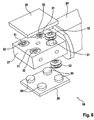
- Fig. 8 shows the first extension 27 of the base body 24 in detail.
- the second extension 28 is constructed in the same way, but rotated by 90 ° about the axis of rotation 17.
- the piston 29 represents a flat surface for the backlash-free system.
- knobs 30 are provided on the inside of the pistons 29.
- the knobs 30 are each in a hydraulic pressure chamber 31.
- a spring 32 designed as a plate spring. The springs 32 and the corresponding pressure in the hydraulic pressure chambers 31 push the pistons 29 away from the first extension 27.
- Fig. 9 shows a sectional view of hydraulic channels 33 for supplying pressure to the hydraulic chambers 31.
- a check valve 34 ensures sufficient pressure maintenance in the hydraulic pressure chambers 31. Hydraulic oil is preferably conveyed from the internal combustion engine 2 into the hydraulic channels 33 and thus into the hydraulic pressure chambers 31 via the check valve 34.
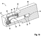
- Fig. 10 shows the design of the base body 24 according to a further embodiment.
- a large piston 29 is provided on each extension 27, 28.
- These large pistons 29 are also loaded via springs 32 and are located in hydraulic pressure chambers 31.
- Fig. 10 shows that a piston 29 is provided on each extension 27, 28 only on one side. Alternatively, however, two opposite pistons 29 could be used on each extension 27, 28.
- FIG. 10 shows Fig. 10 that 29 outlet openings 35 are provided in the piston. Oil can emerge from the hydraulic pressure pressure chambers 31 through these outlet openings 35.
- the outlet openings 35 each represent throttles in order to regulate the pressure in the hydraulic pressure chambers 31.
- the escaping oil serves to lubricate the surfaces between the clutch 10 and the two shafts 3, 7.
- Fig. 11 shows a further embodiment for the cross disc clutch. According to Fig. 11 there are a plurality of small pistons 29 arranged next to one another in both extensions 27, 28. Each piston 29 sits in its own hydraulic pressure chamber 31 and is designed as a spring 32 of its own Coil spring, loaded. In the exemplary embodiment shown, four pistons 29 are used per extension 27, 28.
- Fig. 12 shows the assembled state of the clutch assembly 1 according to a further embodiment, which is not part of the invention.
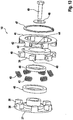
- Fig. 13 shows an exploded view of the associated clutch 10.
- the clutch 10 comprises a first ring 37, a second ring 39 and a compensating ring 41.
- the first ring 37 has an inner cone which is fitted on an outer cone on the first shaft 3. Furthermore, a clamping screw 49 is screwed into the first shaft 3 and fixes the first ring 37 on the first shaft 3 via a clamping disk 48.
- the second ring 39 is mounted on the second shaft 7 in a rotationally fixed manner by means of a cone clamping element 46 and a clamping sleeve 45.
- a locking ring 47 secures the axial position of the compensating ring 41 relative to the second ring 39.
- the first ring 37 has first claws 38.
- the second ring 39 has second claws 40.
- the first and second claws 38, 40 preferably extend in the axial direction.
- the compensating ring 41 has compensating claws 42.
- the compensating claws preferably extend in the radial direction 19.
- the first claws 38, second claws 40 and compensating claws 42 interlock. Viewed in the circumferential direction 18, there is a compensating claw 42 between a first claw 38 and a second claw 40.
- each of these pockets 44 there is a spring 43, in particular a spiral compression spring.
- the respective spring 43 is supported at one end in the pocket 44 and at the other end against a second claw 40.
- the spring 43 pushes the respective compensating claw 42 away from the second claw 40.
- the compensating claw 42 presses on one of the first claws 38, which in turn presses this first claw 38 against the next second claw 40.
- the invention relates to a clutch arrangement 1, comprising a first shaft 3, preferably a crankshaft of an internal combustion engine 2, a second shaft 7, preferably an armature shaft of an electrical machine 6, coaxial with the first shaft 3, and a clutch 10 for connecting the first shaft without play 3 with the second shaft 7, wherein a rotation axis 17 is defined according to the two coaxial shafts 3, 7, a circumferential direction 18 is defined around the rotation axis 17, and a radial direction 19 is defined perpendicular to the rotation axis 17, the coupling 10 at least one movement element 14, 31, 32, 43 and at least one coupling element 11, 29, 41 movable in the circumferential direction 18 and / or in the radial direction 19 with respect to the two shafts 3, 7, and wherein the movement element 14, 31, 32, 43 is designed to around the coupling element 11, 29, 41 in the circumferential direction 18 and / or radial direction 19 without play to the first and / or z wide shaft 3, 7 to press to compensate for a play in the circumferential direction 18
Landscapes
- Engineering & Computer Science (AREA)
- General Engineering & Computer Science (AREA)
- Mechanical Engineering (AREA)
- Mechanical Operated Clutches (AREA)
- Retarders (AREA)
- Shafts, Cranks, Connecting Bars, And Related Bearings (AREA)
- Transmission Devices (AREA)
Claims (12)
- Dispositif d'embrayage (1) comprenant :- un premier arbre (3), de préférence le vilebrequin d'un moteur à combustion interne (2),- un second arbre (7) monté coaxialement au premier arbre (3) en particulier l'arbre d'induit d'une machine électrique (6), et- un embrayage (10) permettant de relier sans jeu le premier arbre (3) avec la second arbre (7),- un axe de rotation (17) étant défini par les deux arbres coaxiaux (3, 7) autour de l'axe de rotation (17) une direction périphérique (18) étant définie et perpendiculairement à l'axe de rotation (17) une direction radiale (19) étant définie,- l'embrayage (10) comprenant au moins un élément de déplacement (14, 31, 32, 43), et au moins un élément d'embrayage (11, 29, 41) mobile par rapport aux deux arbres (3, 7) dans la direction périphérique (18) et/ou dans la direction radiale (19), et- l'élément de déplacement (14, 31, 32, 43) étant réalisé pour permettre de serrer l'élément d'embrayage (11, 29, 41) dans la direction périphérique (18) et/ou dans la direction radiale (19) sans jeu contre le premier arbre et/ou contre le second arbre (3, 7), pour compenser le jeu en direction périphérique (18) entre les deux arbres (3, 7),caractérisé en ce que
l'embrayage (10) comporte en tant qu'élément d'embrayage un premier arbre cannelé (11), un second arbre cannelé (12) et un troisième arbre cannelé (13) monté entre le premier arbre cannelé (11) et le second arbre cannelé (12), les trois arbres cannelés (11, 13) étant montés coaxialement à l'axe de rotation (17) et le premier arbre cannelé (11) étant relié au second arbre cannelé (12) par l'intermédiaire d'un ressort de torsion (14). - Dispositif d'embrayage conforme à la revendication 1,
caractérisé en ce que- le premier arbre (3) comporte une première cannelure d'arbre, et- le second arbre (7) comporte une seconde cannelure d'arbre,- la première cannelure d'arbre vient en prise avec le premier arbre cannelé (11) et simultanément avec le troisième arbre cannelé (13),- la seconde cannelure d'arbre vient en prise avec le second arbre cannelé (12) et simultanément avec le troisième arbre cannelé (13). - Dispositif d'embrayage conforme à l'une des revendications 1 et 2,
caractérisé en ce que
le premier arbre cannelé (11) et le second arbre cannelé (12) sont respectivement reliés solidairement en rotation avec le ressort de torsion (14) et le troisième arbre cannelé (13) est monté mobile en rotation par rapport au ressort de torsion (14). - Dispositif d'embrayage conforme à l'une des revendications précédentes,
caractérisé en ce que
le troisième arbre cannelé (13) est creux et le ressort de torsion (14) s'étend au travers du troisième arbre cannelé (13). - Dispositif d'embrayage (1) conforme à l'une des revendications précédentes comprenant :- un premier arbre (3) de préférence le vilebrequin d'un moteur à combustion interne (2),- un second arbre (7) monté coaxialement au premier arbre (3), de préférence l'arbre d'induit d'une machine électrique (6), et- un embrayage (10) permettant de relier sans jeu le premier arbre (3) et le second arbre (7),- dans lequel un axe de rotation (17) est défini par les deux arbres coaxiaux (3, 7), une direction périphérique (18) est définie autour de l'axe de rotation (17) et une direction axiale (19) est définie perpendiculairement à l'axe de rotation (17),- l'embrayage (10) comprenant au moins un élément de déplacement (14, 31, 32, 33) et au moins un élément d'embrayage (11, 29, 41) mobile par rapport aux deux arbres (3, 7) dans la direction périphérique (18) et/ou dans la direction radiale (19), et- l'élément de déplacement (14, 31, 32, 43) étant réalisé pour permettre de serrer l'élément d'embrayage (11, 29, 41) dans la direction périphérique (18) et/ou dans la direction radiale (19), sans jeu, contre le premier arbre et/ou contre le second arbre (3, 7) pour permettre de compenser un jeu dans la direction périphérique (18) entre les deux arbres (3, 7),caractérisé en ce que
l'embrayage (10) est réalisé sous la forme d'un embrayage à joint de Oldham et comporte corps de base rotatif (24),- les deux arbres (3, 7) comprennent respectivement une rainure (25, 26) et le corps de base (24) s'enfiche par des prolongements (27, 28) dans les rainures (25, 26),- au moins un élément d'embrayage est formé par un piston (29) qui est monté mobile en direction radiale (19) dans le corps de base (24),- l'élément de déplacement sollicite le piston (29) pour l'éloigner du corps de base (24), de sorte qu'il s'applique contre le premier arbre ou contre le second arbre (3, 7). - Dispositif d'embrayage conforme à la revendication 5,
caractérisé en ce que
sur la face du corps de base (24) tournée vers le premier arbre (3) et sur la face du corps de base (24) tournée vers le second arbre (7) sont respectivement montés plusieurs pistons (29) mobiles dans la direction radiale (19). - Dispositif d'embrayage conforme à l'une des revendications précédentes,
caractérisé en ce que
l'élément de déplacement est un rotor (14, 32, 43) et/ou une chambre de pression hydraulique (31). - Procédé de montage d'un dispositif d'embrayage (1) conforme à l'une des revendications 1 à 4,
comprenant les étapes suivantes consistant à :- tendre le ressort de torsion (14) par rotation du premier arbre cannelé (11) par rapport au second arbre cannelé (12),- introduire une première protection anti-rotation (15) qui fixe le premier arbre cannelé (11) par rapport au troisième arbre cannelé (13) et une seconde protection anti-rotation (15) qui fixe le second arbre cannelé (12) par rapport au troisième arbre cannelé (13),- monter le premier arbre cannelé (11) sur le premier arbre (3) et le second arbre cannelé (12) sur le second arbre (7), et- dégager les deux protections anti-rotation (15). - Procédé conforme à la revendication 8,
caractérisé en ce qu'
en tant que première protection anti-rotation (15) on fait glisser un premier manchon qui pour permettre la fixation vient en prise simultanément dans la cannelure du premier arbre cannelé (11) et dans la denture du troisième arbre cannelé (13), et/ou en tant que seconde protection anti-rotation (15) on fait glisser un second manchon qui, pour permettre la fixation vient simultanément en prise dans la cannelure du second arbre cannelé (12) et dans la cannelure du troisième arbre cannelé (13). - Procédé conforme à la revendication 9,
caractérisé en ce que
lors du montage du premier arbre cannelé (11) sur le premier arbre (3) le premier manchon est totalement glissé sur le troisième arbre cannelé (13), et/ou lors du montage du second arbre cannelé (12) sur le second arbre (7) le second manchon est totalement glissé sur le troisième arbre cannelé (13). - Procédé conforme à l'une des revendications 8 à 10,
caractérisé en ce qu'
en tant que première protection anti-rotation (15) on insère au moins une première broche (21) qui pour permettre la fixation s'enfiche simultanément dans le premier arbre cannelé (11) et dans le troisième arbre cannelé (13), et/ou en tant que seconde protection anti-rotation (15) on insère au moins une seconde broche (21) qui, pour permettre la fixation s'enfiche simultanément dans le second arbre cannelé (12), et dans le troisième arbre cannelé (13). - Procédé conforme à la revendication 11,
caractérisé en ce que
lors du montage du premier arbre cannelé (11) sur le premier arbre (3) la première broche (21) est totalement insérée dans le troisième arbre cannelé (13) et/ou lors du montage du second arbre cannelé (12) sur le second arbre (7) la seconde broche (21) est totalement insérée dans le troisième arbre cannelé (13).
Applications Claiming Priority (2)
| Application Number | Priority Date | Filing Date | Title |
|---|---|---|---|
| DE102013205531.5A DE102013205531A1 (de) | 2013-03-28 | 2013-03-28 | Kupplungsanordnung |
| PCT/EP2014/052706 WO2014154392A1 (fr) | 2013-03-28 | 2014-02-12 | Système d'embrayage |
Publications (2)
| Publication Number | Publication Date |
|---|---|
| EP2978986A1 EP2978986A1 (fr) | 2016-02-03 |
| EP2978986B1 true EP2978986B1 (fr) | 2020-01-01 |
Family
ID=50073207
Family Applications (1)
| Application Number | Title | Priority Date | Filing Date |
|---|---|---|---|
| EP14703875.6A Active EP2978986B1 (fr) | 2013-03-28 | 2014-02-12 | Système d'embrayage |
Country Status (5)
| Country | Link |
|---|---|
| US (1) | US9964157B2 (fr) |
| EP (1) | EP2978986B1 (fr) |
| CN (1) | CN104919200B (fr) |
| DE (1) | DE102013205531A1 (fr) |
| WO (1) | WO2014154392A1 (fr) |
Families Citing this family (4)
| Publication number | Priority date | Publication date | Assignee | Title |
|---|---|---|---|---|
| RU2648535C1 (ru) * | 2016-11-28 | 2018-03-26 | Апетян Павел Мкртычевич | Гидро-кулачковая муфта |
| DE102018219826A1 (de) * | 2017-12-19 | 2019-06-19 | Heidelberger Druckmaschinen Ag | Druckkopf-Justagevorrichtung und Druckbalken |
| DE102018205866A1 (de) * | 2018-04-18 | 2019-10-24 | Robert Bosch Gmbh | Antriebswelle für eine Hochdruckpumpe, Hochdruckpumpe |
| CN116447242B (zh) * | 2023-03-20 | 2025-06-13 | 江苏玄博智能标识科技有限公司 | 一种金属切割设备的转轴连接件及传动机构 |
Family Cites Families (18)
| Publication number | Priority date | Publication date | Assignee | Title |
|---|---|---|---|---|
| US1337646A (en) * | 1919-07-24 | 1920-04-20 | George F Eckart | Flexible coupling |
| GB691281A (en) * | 1951-02-19 | 1953-05-06 | Transp Equipment Thorneycroft | Improvements in or relating to shaft couplings |
| US4332148A (en) * | 1980-06-04 | 1982-06-01 | General Motors Corporation | Cyclic phase-change coupling |
| DE3621187A1 (de) * | 1986-06-25 | 1988-01-21 | Hackforth Gmbh & Co Kg | Elastische wellenkupplung |
| US5355748A (en) | 1991-05-31 | 1994-10-18 | Ntn Corporation | Rotation transmitting device for an interaxle gearless differential |
| FR2682636B1 (fr) | 1991-10-21 | 1994-01-21 | Rapidex Sm | Ligne modulaire de fabrication d'emballages en carton. |
| ID16898A (id) * | 1996-05-14 | 1997-11-20 | Toyota Motor Co Ltd | Peralatan variabel tempo katup untuk internal mesin pembakar |
| US5984223A (en) * | 1998-06-05 | 1999-11-16 | Takata Corporation | Seat belt retractor and its spool |
| EP1148009A1 (fr) * | 2000-04-20 | 2001-10-24 | Grapha-Holding Ag | Arbre à griffes pour un margeur |
| CN101405516A (zh) * | 2006-03-22 | 2009-04-08 | 卢克摩擦片和离合器两合公司 | 允许径向移位的转矩传递装置以及离合器盘 |
| US7658678B2 (en) * | 2007-01-17 | 2010-02-09 | The Gates Corporation | Pronged sleeve-type flexible shaft coupling |
| CN201113641Y (zh) * | 2007-09-17 | 2008-09-10 | 襄樊特种电机有限公司 | 一种客车用发电机 |
| CN201221573Y (zh) * | 2008-05-23 | 2009-04-15 | 袁志成 | 一种联轴器 |
| CN101858390A (zh) * | 2010-06-13 | 2010-10-13 | 太仓成铭液压机械有限公司 | 一种联轴器 |
| CN201794939U (zh) * | 2010-08-05 | 2011-04-13 | 叶笃孟 | 一种液压联轴器 |
| CN201891756U (zh) * | 2010-11-30 | 2011-07-06 | 广州能之原节能技术有限公司 | 一种伺服电机与油泵间的联接装置 |
| CN202125527U (zh) * | 2011-05-12 | 2012-01-25 | 株洲时代新材料科技股份有限公司 | 一种风力发电机组传动链柔性连接弹性元件 |
| DE102012223993A1 (de) * | 2012-01-27 | 2013-08-01 | Schaeffler Technologies AG & Co. KG | Drehmomentübertragungseinrichung mit Anbindung eines Wandlers nach Art einer flexiblen Hybridkopfanbindung sowie Versatzausgleichseinrichtung und Antriebsstrang |
-
2013
- 2013-03-28 DE DE102013205531.5A patent/DE102013205531A1/de not_active Withdrawn
-
2014
- 2014-02-12 EP EP14703875.6A patent/EP2978986B1/fr active Active
- 2014-02-12 WO PCT/EP2014/052706 patent/WO2014154392A1/fr not_active Ceased
- 2014-02-12 CN CN201480004995.7A patent/CN104919200B/zh active Active
-
2015
- 2015-09-25 US US14/865,470 patent/US9964157B2/en active Active
Non-Patent Citations (1)
| Title |
|---|
| None * |
Also Published As
| Publication number | Publication date |
|---|---|
| US20160010696A1 (en) | 2016-01-14 |
| EP2978986A1 (fr) | 2016-02-03 |
| DE102013205531A1 (de) | 2014-10-02 |
| CN104919200A (zh) | 2015-09-16 |
| WO2014154392A1 (fr) | 2014-10-02 |
| CN104919200B (zh) | 2019-02-05 |
| US9964157B2 (en) | 2018-05-08 |
Similar Documents
| Publication | Publication Date | Title |
|---|---|---|
| EP1552116B1 (fr) | Dispositif de reglage de l'arbre a cames a entrainement electrique | |
| WO2004035997A1 (fr) | Dispositif de reglage d'arbre a cames a entrainement electrique | |
| EP1515059A1 (fr) | Dispositif de fixation axiale d'un embrayage sur un joint rotatif | |
| EP2060824B1 (fr) | Agencement d'amortisseur de vibrations de torsions | |
| WO2018157879A1 (fr) | Système d'embrayage multiple et module hybride pour véhicule à moteur | |
| DE112015002170T5 (de) | Kopplungsverfahren für elektrische Versteller | |
| DE102013205531A1 (de) | Kupplungsanordnung | |
| DE102014200331B4 (de) | Ölpumpenantrieb mit schaltbarer Antriebsübersetzung | |
| DE102006028269A1 (de) | Überlagerungsgetriebe | |
| DE102016108876A1 (de) | Vorrichtung zur Betätigung eines Eingangsglieds | |
| DE102004041751A1 (de) | Nockenwellenversteller | |
| DE102011103495A1 (de) | Kupplungswelle,Aktor,Nockenwellenverstellgetriebe und Nockenwellensteller | |
| EP3504453A1 (fr) | Double ressort enroulé, dispositif de rotation et système devant être actionné | |
| WO2009003686A1 (fr) | Unité d'accouplement pour des groupes auxiliaires d'un moteur à combustion interne | |
| DE10221625A1 (de) | Vorrichtung zur Kopplung einer Gehäuseanordnung einer Kopplungseinrichtung mit einer Rotoranordnung einer Elektromaschine | |
| DE102011008703A1 (de) | Vorrichtung zur trieblichen Verbindung | |
| DE102004058177B4 (de) | Zahnrad | |
| DE102007023617B4 (de) | Nockenwellenversteller | |
| DE102016214711A1 (de) | Doppelschlingfeder, Rotationseinrichtung und zu aktuierendes System | |
| DE3531848A1 (de) | Zahnrad-druckluftstarter | |
| EP1666769A1 (fr) | Roue dentée | |
| WO2016184834A1 (fr) | Système déphaseur d'arbre à cames | |
| DE102021211648B4 (de) | Welle-Nabe-Verbindung | |
| DE102019117346B3 (de) | Elektromechanische Wasserpumpe mit Freilauf | |
| DE202011002172U1 (de) | Bolzenkupplung |
Legal Events
| Date | Code | Title | Description |
|---|---|---|---|
| PUAI | Public reference made under article 153(3) epc to a published international application that has entered the european phase |
Free format text: ORIGINAL CODE: 0009012 |
|
| 17P | Request for examination filed |
Effective date: 20150813 |
|
| AK | Designated contracting states |
Kind code of ref document: A1 Designated state(s): AL AT BE BG CH CY CZ DE DK EE ES FI FR GB GR HR HU IE IS IT LI LT LU LV MC MK MT NL NO PL PT RO RS SE SI SK SM TR |
|
| AX | Request for extension of the european patent |
Extension state: BA ME |
|
| DAX | Request for extension of the european patent (deleted) | ||
| STAA | Information on the status of an ep patent application or granted ep patent |
Free format text: STATUS: EXAMINATION IS IN PROGRESS |
|
| 17Q | First examination report despatched |
Effective date: 20181204 |
|
| GRAP | Despatch of communication of intention to grant a patent |
Free format text: ORIGINAL CODE: EPIDOSNIGR1 |
|
| STAA | Information on the status of an ep patent application or granted ep patent |
Free format text: STATUS: GRANT OF PATENT IS INTENDED |
|
| INTG | Intention to grant announced |
Effective date: 20190321 |
|
| GRAS | Grant fee paid |
Free format text: ORIGINAL CODE: EPIDOSNIGR3 |
|
| GRAJ | Information related to disapproval of communication of intention to grant by the applicant or resumption of examination proceedings by the epo deleted |
Free format text: ORIGINAL CODE: EPIDOSDIGR1 |
|
| GRAL | Information related to payment of fee for publishing/printing deleted |
Free format text: ORIGINAL CODE: EPIDOSDIGR3 |
|
| STAA | Information on the status of an ep patent application or granted ep patent |
Free format text: STATUS: EXAMINATION IS IN PROGRESS |
|
| INTC | Intention to grant announced (deleted) | ||
| GRAJ | Information related to disapproval of communication of intention to grant by the applicant or resumption of examination proceedings by the epo deleted |
Free format text: ORIGINAL CODE: EPIDOSDIGR1 |
|
| GRAP | Despatch of communication of intention to grant a patent |
Free format text: ORIGINAL CODE: EPIDOSNIGR1 |
|
| GRAP | Despatch of communication of intention to grant a patent |
Free format text: ORIGINAL CODE: EPIDOSNIGR1 |
|
| STAA | Information on the status of an ep patent application or granted ep patent |
Free format text: STATUS: GRANT OF PATENT IS INTENDED |
|
| INTG | Intention to grant announced |
Effective date: 20190906 |
|
| GRAA | (expected) grant |
Free format text: ORIGINAL CODE: 0009210 |
|
| STAA | Information on the status of an ep patent application or granted ep patent |
Free format text: STATUS: THE PATENT HAS BEEN GRANTED |
|
| AK | Designated contracting states |
Kind code of ref document: B1 Designated state(s): AL AT BE BG CH CY CZ DE DK EE ES FI FR GB GR HR HU IE IS IT LI LT LU LV MC MK MT NL NO PL PT RO RS SE SI SK SM TR |
|
| REG | Reference to a national code |
Ref country code: GB Ref legal event code: FG4D Free format text: NOT ENGLISH |
|
| REG | Reference to a national code |
Ref country code: CH Ref legal event code: EP Ref country code: AT Ref legal event code: REF Ref document number: 1220135 Country of ref document: AT Kind code of ref document: T Effective date: 20200115 |
|
| REG | Reference to a national code |
Ref country code: DE Ref legal event code: R096 Ref document number: 502014013372 Country of ref document: DE |
|
| REG | Reference to a national code |
Ref country code: IE Ref legal event code: FG4D Free format text: LANGUAGE OF EP DOCUMENT: GERMAN |
|
| REG | Reference to a national code |
Ref country code: NL Ref legal event code: MP Effective date: 20200101 |
|
| REG | Reference to a national code |
Ref country code: LT Ref legal event code: MG4D |
|
| PG25 | Lapsed in a contracting state [announced via postgrant information from national office to epo] |
Ref country code: NO Free format text: LAPSE BECAUSE OF FAILURE TO SUBMIT A TRANSLATION OF THE DESCRIPTION OR TO PAY THE FEE WITHIN THE PRESCRIBED TIME-LIMIT Effective date: 20200401 Ref country code: FI Free format text: LAPSE BECAUSE OF FAILURE TO SUBMIT A TRANSLATION OF THE DESCRIPTION OR TO PAY THE FEE WITHIN THE PRESCRIBED TIME-LIMIT Effective date: 20200101 Ref country code: RS Free format text: LAPSE BECAUSE OF FAILURE TO SUBMIT A TRANSLATION OF THE DESCRIPTION OR TO PAY THE FEE WITHIN THE PRESCRIBED TIME-LIMIT Effective date: 20200101 Ref country code: CZ Free format text: LAPSE BECAUSE OF FAILURE TO SUBMIT A TRANSLATION OF THE DESCRIPTION OR TO PAY THE FEE WITHIN THE PRESCRIBED TIME-LIMIT Effective date: 20200101 Ref country code: NL Free format text: LAPSE BECAUSE OF FAILURE TO SUBMIT A TRANSLATION OF THE DESCRIPTION OR TO PAY THE FEE WITHIN THE PRESCRIBED TIME-LIMIT Effective date: 20200101 Ref country code: LT Free format text: LAPSE BECAUSE OF FAILURE TO SUBMIT A TRANSLATION OF THE DESCRIPTION OR TO PAY THE FEE WITHIN THE PRESCRIBED TIME-LIMIT Effective date: 20200101 Ref country code: PT Free format text: LAPSE BECAUSE OF FAILURE TO SUBMIT A TRANSLATION OF THE DESCRIPTION OR TO PAY THE FEE WITHIN THE PRESCRIBED TIME-LIMIT Effective date: 20200527 |
|
| PG25 | Lapsed in a contracting state [announced via postgrant information from national office to epo] |
Ref country code: GR Free format text: LAPSE BECAUSE OF FAILURE TO SUBMIT A TRANSLATION OF THE DESCRIPTION OR TO PAY THE FEE WITHIN THE PRESCRIBED TIME-LIMIT Effective date: 20200402 Ref country code: BG Free format text: LAPSE BECAUSE OF FAILURE TO SUBMIT A TRANSLATION OF THE DESCRIPTION OR TO PAY THE FEE WITHIN THE PRESCRIBED TIME-LIMIT Effective date: 20200401 Ref country code: IS Free format text: LAPSE BECAUSE OF FAILURE TO SUBMIT A TRANSLATION OF THE DESCRIPTION OR TO PAY THE FEE WITHIN THE PRESCRIBED TIME-LIMIT Effective date: 20200501 Ref country code: SE Free format text: LAPSE BECAUSE OF FAILURE TO SUBMIT A TRANSLATION OF THE DESCRIPTION OR TO PAY THE FEE WITHIN THE PRESCRIBED TIME-LIMIT Effective date: 20200101 Ref country code: LV Free format text: LAPSE BECAUSE OF FAILURE TO SUBMIT A TRANSLATION OF THE DESCRIPTION OR TO PAY THE FEE WITHIN THE PRESCRIBED TIME-LIMIT Effective date: 20200101 Ref country code: HR Free format text: LAPSE BECAUSE OF FAILURE TO SUBMIT A TRANSLATION OF THE DESCRIPTION OR TO PAY THE FEE WITHIN THE PRESCRIBED TIME-LIMIT Effective date: 20200101 |
|
| REG | Reference to a national code |
Ref country code: CH Ref legal event code: PL |
|
| REG | Reference to a national code |
Ref country code: DE Ref legal event code: R097 Ref document number: 502014013372 Country of ref document: DE |
|
| REG | Reference to a national code |
Ref country code: BE Ref legal event code: MM Effective date: 20200229 |
|
| PG25 | Lapsed in a contracting state [announced via postgrant information from national office to epo] |
Ref country code: LU Free format text: LAPSE BECAUSE OF NON-PAYMENT OF DUE FEES Effective date: 20200212 Ref country code: SK Free format text: LAPSE BECAUSE OF FAILURE TO SUBMIT A TRANSLATION OF THE DESCRIPTION OR TO PAY THE FEE WITHIN THE PRESCRIBED TIME-LIMIT Effective date: 20200101 Ref country code: MC Free format text: LAPSE BECAUSE OF FAILURE TO SUBMIT A TRANSLATION OF THE DESCRIPTION OR TO PAY THE FEE WITHIN THE PRESCRIBED TIME-LIMIT Effective date: 20200101 Ref country code: EE Free format text: LAPSE BECAUSE OF FAILURE TO SUBMIT A TRANSLATION OF THE DESCRIPTION OR TO PAY THE FEE WITHIN THE PRESCRIBED TIME-LIMIT Effective date: 20200101 Ref country code: DK Free format text: LAPSE BECAUSE OF FAILURE TO SUBMIT A TRANSLATION OF THE DESCRIPTION OR TO PAY THE FEE WITHIN THE PRESCRIBED TIME-LIMIT Effective date: 20200101 Ref country code: SM Free format text: LAPSE BECAUSE OF FAILURE TO SUBMIT A TRANSLATION OF THE DESCRIPTION OR TO PAY THE FEE WITHIN THE PRESCRIBED TIME-LIMIT Effective date: 20200101 Ref country code: ES Free format text: LAPSE BECAUSE OF FAILURE TO SUBMIT A TRANSLATION OF THE DESCRIPTION OR TO PAY THE FEE WITHIN THE PRESCRIBED TIME-LIMIT Effective date: 20200101 Ref country code: RO Free format text: LAPSE BECAUSE OF FAILURE TO SUBMIT A TRANSLATION OF THE DESCRIPTION OR TO PAY THE FEE WITHIN THE PRESCRIBED TIME-LIMIT Effective date: 20200101 |
|
| PLBE | No opposition filed within time limit |
Free format text: ORIGINAL CODE: 0009261 |
|
| STAA | Information on the status of an ep patent application or granted ep patent |
Free format text: STATUS: NO OPPOSITION FILED WITHIN TIME LIMIT |
|
| PG25 | Lapsed in a contracting state [announced via postgrant information from national office to epo] |
Ref country code: CH Free format text: LAPSE BECAUSE OF NON-PAYMENT OF DUE FEES Effective date: 20200229 Ref country code: LI Free format text: LAPSE BECAUSE OF NON-PAYMENT OF DUE FEES Effective date: 20200229 |
|
| 26N | No opposition filed |
Effective date: 20201002 |
|
| PG25 | Lapsed in a contracting state [announced via postgrant information from national office to epo] |
Ref country code: IE Free format text: LAPSE BECAUSE OF NON-PAYMENT OF DUE FEES Effective date: 20200212 Ref country code: IT Free format text: LAPSE BECAUSE OF FAILURE TO SUBMIT A TRANSLATION OF THE DESCRIPTION OR TO PAY THE FEE WITHIN THE PRESCRIBED TIME-LIMIT Effective date: 20200101 |
|
| PG25 | Lapsed in a contracting state [announced via postgrant information from national office to epo] |
Ref country code: PL Free format text: LAPSE BECAUSE OF FAILURE TO SUBMIT A TRANSLATION OF THE DESCRIPTION OR TO PAY THE FEE WITHIN THE PRESCRIBED TIME-LIMIT Effective date: 20200101 Ref country code: SI Free format text: LAPSE BECAUSE OF FAILURE TO SUBMIT A TRANSLATION OF THE DESCRIPTION OR TO PAY THE FEE WITHIN THE PRESCRIBED TIME-LIMIT Effective date: 20200101 Ref country code: BE Free format text: LAPSE BECAUSE OF NON-PAYMENT OF DUE FEES Effective date: 20200229 |
|
| REG | Reference to a national code |
Ref country code: AT Ref legal event code: MM01 Ref document number: 1220135 Country of ref document: AT Kind code of ref document: T Effective date: 20200212 |
|
| PG25 | Lapsed in a contracting state [announced via postgrant information from national office to epo] |
Ref country code: AT Free format text: LAPSE BECAUSE OF NON-PAYMENT OF DUE FEES Effective date: 20200212 |
|
| PG25 | Lapsed in a contracting state [announced via postgrant information from national office to epo] |
Ref country code: TR Free format text: LAPSE BECAUSE OF FAILURE TO SUBMIT A TRANSLATION OF THE DESCRIPTION OR TO PAY THE FEE WITHIN THE PRESCRIBED TIME-LIMIT Effective date: 20200101 Ref country code: MT Free format text: LAPSE BECAUSE OF FAILURE TO SUBMIT A TRANSLATION OF THE DESCRIPTION OR TO PAY THE FEE WITHIN THE PRESCRIBED TIME-LIMIT Effective date: 20200101 Ref country code: CY Free format text: LAPSE BECAUSE OF FAILURE TO SUBMIT A TRANSLATION OF THE DESCRIPTION OR TO PAY THE FEE WITHIN THE PRESCRIBED TIME-LIMIT Effective date: 20200101 |
|
| PG25 | Lapsed in a contracting state [announced via postgrant information from national office to epo] |
Ref country code: MK Free format text: LAPSE BECAUSE OF FAILURE TO SUBMIT A TRANSLATION OF THE DESCRIPTION OR TO PAY THE FEE WITHIN THE PRESCRIBED TIME-LIMIT Effective date: 20200101 Ref country code: AL Free format text: LAPSE BECAUSE OF FAILURE TO SUBMIT A TRANSLATION OF THE DESCRIPTION OR TO PAY THE FEE WITHIN THE PRESCRIBED TIME-LIMIT Effective date: 20200101 |
|
| P01 | Opt-out of the competence of the unified patent court (upc) registered |
Effective date: 20230502 |
|
| PGFP | Annual fee paid to national office [announced via postgrant information from national office to epo] |
Ref country code: GB Payment date: 20260219 Year of fee payment: 13 |
|
| PGFP | Annual fee paid to national office [announced via postgrant information from national office to epo] |
Ref country code: DE Payment date: 20260210 Year of fee payment: 13 |
|
| PGFP | Annual fee paid to national office [announced via postgrant information from national office to epo] |
Ref country code: FR Payment date: 20260223 Year of fee payment: 13 |