EP2979352B1 - Dispositif, en particulier machine ou installation, et procédé permettant de faire fonctionner un dispositif - Google Patents
Dispositif, en particulier machine ou installation, et procédé permettant de faire fonctionner un dispositif Download PDFInfo
- Publication number
- EP2979352B1 EP2979352B1 EP14706478.6A EP14706478A EP2979352B1 EP 2979352 B1 EP2979352 B1 EP 2979352B1 EP 14706478 A EP14706478 A EP 14706478A EP 2979352 B1 EP2979352 B1 EP 2979352B1
- Authority
- EP
- European Patent Office
- Prior art keywords
- converter
- voltage
- rectifier
- energy
- power
- Prior art date
- Legal status (The legal status is an assumption and is not a legal conclusion. Google has not performed a legal analysis and makes no representation as to the accuracy of the status listed.)
- Active
Links
Images



Classifications
-
- H—ELECTRICITY
- H02—GENERATION; CONVERSION OR DISTRIBUTION OF ELECTRIC POWER
- H02J—ELECTRIC POWER NETWORKS; CIRCUIT ARRANGEMENTS OR SYSTEMS FOR SUPPLYING OR DISTRIBUTING ELECTRIC POWER; SYSTEMS FOR STORING ELECTRIC ENERGY
- H02J1/00—Circuit arrangements for DC mains or DC distribution networks
- H02J1/10—Parallel operation of DC sources
-
- H—ELECTRICITY
- H02—GENERATION; CONVERSION OR DISTRIBUTION OF ELECTRIC POWER
- H02P—CONTROL OR REGULATION OF ELECTRIC MOTORS, ELECTRIC GENERATORS OR DYNAMO-ELECTRIC CONVERTERS; CONTROLLING TRANSFORMERS, REACTORS OR CHOKE COILS
- H02P3/00—Arrangements for stopping or slowing electric motors, generators, or dynamo-electric converters
-
- H—ELECTRICITY
- H02—GENERATION; CONVERSION OR DISTRIBUTION OF ELECTRIC POWER
- H02J—ELECTRIC POWER NETWORKS; CIRCUIT ARRANGEMENTS OR SYSTEMS FOR SUPPLYING OR DISTRIBUTING ELECTRIC POWER; SYSTEMS FOR STORING ELECTRIC ENERGY
- H02J7/00—Circuit arrangements for charging or discharging batteries or for supplying loads from batteries
- H02J7/34—Parallel operation in networks using both storage and other DC sources, e.g. providing buffering
-
- H—ELECTRICITY
- H02—GENERATION; CONVERSION OR DISTRIBUTION OF ELECTRIC POWER
- H02M—APPARATUS FOR CONVERSION BETWEEN AC AND AC, BETWEEN AC AND DC, OR BETWEEN DC AND DC, AND FOR USE WITH MAINS OR SIMILAR POWER SUPPLY SYSTEMS; CONVERSION OF DC OR AC INPUT POWER INTO SURGE OUTPUT POWER; CONTROL OR REGULATION THEREOF
- H02M1/00—Details of apparatus for conversion
- H02M1/10—Arrangements incorporating converting means for enabling loads to be operated at will from different kinds of power supplies, e.g. from AC or DC
-
- H—ELECTRICITY
- H02—GENERATION; CONVERSION OR DISTRIBUTION OF ELECTRIC POWER
- H02M—APPARATUS FOR CONVERSION BETWEEN AC AND AC, BETWEEN AC AND DC, OR BETWEEN DC AND DC, AND FOR USE WITH MAINS OR SIMILAR POWER SUPPLY SYSTEMS; CONVERSION OF DC OR AC INPUT POWER INTO SURGE OUTPUT POWER; CONTROL OR REGULATION THEREOF
- H02M3/00—Conversion of DC power input into DC power output
- H02M3/02—Conversion of DC power input into DC power output without intermediate conversion into AC
- H02M3/04—Conversion of DC power input into DC power output without intermediate conversion into AC by static converters
- H02M3/10—Conversion of DC power input into DC power output without intermediate conversion into AC by static converters using discharge tubes with control electrode or semiconductor devices with control electrode
- H02M3/145—Conversion of DC power input into DC power output without intermediate conversion into AC by static converters using discharge tubes with control electrode or semiconductor devices with control electrode using devices of a triode or transistor type requiring continuous application of a control signal
- H02M3/155—Conversion of DC power input into DC power output without intermediate conversion into AC by static converters using discharge tubes with control electrode or semiconductor devices with control electrode using devices of a triode or transistor type requiring continuous application of a control signal using semiconductor devices only
- H02M3/156—Conversion of DC power input into DC power output without intermediate conversion into AC by static converters using discharge tubes with control electrode or semiconductor devices with control electrode using devices of a triode or transistor type requiring continuous application of a control signal using semiconductor devices only with automatic control of output voltage or current, e.g. switching regulators
- H02M3/158—Conversion of DC power input into DC power output without intermediate conversion into AC by static converters using discharge tubes with control electrode or semiconductor devices with control electrode using devices of a triode or transistor type requiring continuous application of a control signal using semiconductor devices only with automatic control of output voltage or current, e.g. switching regulators including plural semiconductor devices as final control devices for a single load
- H02M3/1582—Buck-boost converters
Definitions
- the invention relates to a device, in particular a machine or system, and a method for operating a device.
- inverters feed the energy generated by an electric motor in generator operation back into the unipolar intermediate circuit that otherwise feeds it.
- the invention is therefore based on the object of developing an intermediate circuit with an energy store in a simple manner.
- the object is achieved in the device according to the features specified in claim 1 and in the method according to the features specified in claim 12.
- the advantage here is that, by means of the DC / DC converter, the voltage supplying the energy store and the inverter (s) is independent of the value of the voltage supplying the DC / DC converter.
- the DC / DC converter can be supplied from a rectifier, which can be supplied from a network-side voltage source, in particular wherein the voltage source is a single-phase AC voltage source, in particular wherein the rectifier can be supplied from a voltage source via a plug connection, the plug connection having a Schuko plug connector part and / or the voltage source between 100 volts and 300 volts and between 45 hertz and 65 hertz, in particular 230 volts and 50 hertz.
- the advantage here is that a single-phase supply and thus a supply with very low maximum power, in particular with less than 3 kW, is possible, although the motors are designed as three-phase motors with a maximum power that can be absorbed, which is much greater than the maximum over the power that can be fed to the DC / DC converter. In particular, this is Consumption value an order of magnitude greater than the maximum consumption value of the drives.
- the drives have a peak power of 30 kW or more.
- the rectifier can be supplied from the network-side voltage source by means of a conductor line, in particular by means of a sliding contact, or by means of a trailing line, or wherein the rectifier can be supplied from a secondary winding which is arranged inductively coupled to a primary conductor provided in a stationary manner in the device.
- the respective inverter feeds an electric motor, in particular a three-phase motor, in particular so that mechanical energy can be converted into electrical energy in generator operation.
- an electric motor in particular a three-phase motor, in particular so that mechanical energy can be converted into electrical energy in generator operation.
- the advantage here is that the energy generated as a generator is either consumed immediately in a motor-driven drive or is stored in the energy store.
- no braking resistor is provided in the device and the excess energy generated as a generator is not fed back into the network-side voltage source but can be fed to the energy store and can be stored there.
- the advantage here is that a braking resistor can be saved.
- the DC / DC converter functions as an actuator for the power supplied to the device by the network-side voltage source.
- the advantage here is that the power supplied to the intermediate circuit can be regulated to a specifiable setpoint value.
- the DC / DC converter is designed and set up in such a way that the rectified network-side voltage is always or at least temporarily less than or equal to the voltage occurring on the output side.
- the advantage here is that a high intermediate circuit voltage can still be maintained with a low supply voltage.
- the DC / DC converter has an inductance which is connected in series with a first controllable switch, the output current of the rectifier being fed to this series circuit, in particular wherein a further controllable switch is arranged on the side of the inductance facing away from the first controllable switch, wherein a first series circuit is formed from the first controllable switch and a first diode, which is fed by the voltage feeding the DC / DC converter on the input side, wherein a second series circuit is formed from the second controllable switch and a second diode, the voltage on the output side of the DC / DC converter being provided on it.
- a first series circuit is formed from the first controllable switch and a first diode, which is fed by the voltage feeding the DC / DC converter on the input side
- a second series circuit is formed from the second controllable switch and a second diode, the voltage on the output side of the DC / DC converter being provided on it.
- the DC / DC converter has a series circuit of two controllable switches on the input side and on the output side, the center taps of the series circuits being connected by means of an inductance.
- the current flowing through the inductance can be detected and the detected values are fed to signal electronics, which generate control signals that are fed to the respective controllable switch,
- the output voltage generated on the output side of the DC / DC converter exceeds the voltage value present on the input side of the DC / DC converter, whereby the voltage present on the input side of the DC / DC converter is generated by a rectifier.
- the advantage here is that the voltage can be regulated.
- the energy store is arranged on the movable part of a machine axis in such a way that the airflow generated when the machine axis moves cools the energy store, in particular wherein the housing of the energy store is designed with a high degree of protection, in particular watertight and airtight.
- the advantage here is that a higher power can be implemented, in particular higher charging currents or discharging currents.
- the power carried out by the DC / DC converter on the output side i.e. to the energy store and to the intermediate circuit feeding the inverter or inverters, is regulated or controlled in such a way that the state of charge of the energy store is regulated to a quiescent state of charge .
- the advantage here is that the state of charge of the energy store can be regulated.
- the idle state of charge is a predetermined value.
- the advantage here is that a constant value can be specified.
- this value is selected in such a way that the energy storage device can absorb the portion of the mechanical energy still present in the device, that is, the mechanical energy still present in the system, which can be converted back into electrical energy.
- the idle state of charge is determined as a function of the state of the device, in particular as a function of that portion of the mechanical energy, in particular the kinetic and potential energy, which can be converted back electrically
- the idle state of charge is determined depending on the state of the device in such a way that the energy difference between the maximum permissible and / or achievable state of charge of the energy store and the state of idle charge corresponds to that portion of the mechanical energy, in particular the kinetic and potential energy, which can be converted back electrically.
- the energy store is dimensioned so large that that portion of the maximum mechanical energy present in the device, in particular the kinetic and potential energy, which can be converted back electrically, can be fed into the energy store. The advantage here is that more energy can be stored in the energy store, i.e. the energy store is better utilized while maintaining a high level of security.
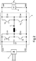
- FIG. 1 a schematic circuit diagram of the device according to the invention is shown schematically, a DC / DC converter 3 being included in the device.
- a three-phase or single-phase AC voltage source 1 supplies a rectifier 2, from which a DC / DC converter 3 is fed, which provides a unipolar intermediate circuit voltage on the output side, from which at least one hoist drive 5, in particular for a vertical movement of a object to be transported, and a chassis drive, in particular for a horizontal movement of an object to be transported, can be supplied.
- an energy store in particular made up of capacitors, in particular double-layer capacitors, is provided, at the connections of which the intermediate circuit voltage is applied.
- Each of the drives has a capacitor arranged on the input side, which, like the energy store, contributes to the intermediate circuit capacitance, and from which an inverter operated with pulse width modulation is supplied, from which an electric motor can be fed in motor mode. In the generator mode of the respective drive (5, 6), energy is fed back into the intermediate circuit.
- the energy fed back by one of the drives (5, 6) can be stored in the energy store 4, provided that it is not used directly by the respective other drive (5, 6).
- the maximum supply power to be generated by the AC voltage source 1 and thus also the associated design of the connection of the rectifier 2 to the AC voltage source 1 can be designed to be correspondingly low.
- the energy storage device can be dimensioned so large that it buffers the motorized power peaks and thus from the AC voltage source 1 to the Rectifier 2 only has to deliver the average power, that is to say the power averaged over long periods of time, so it only has to cover the losses of the application.
- a feedback from the intermediate circuit to the AC voltage source 1 is not necessary.
- the DC / DC converter 3 has an input-side capacitor C1, this being connected in parallel with a series circuit made up of two controllable switches (T1, T2) and a series circuit made up of two diodes (D1, D2).
- An inductance L is fed from the two electrically connected center taps of the two series circuits, whereby the current flowing through the inductance L is detected and is in turn fed to the electrically interconnected center taps of two series circuits connected in parallel, the first series circuit consisting of two controllable switches ( T3, T4) and the second series connection consists of two diodes (D3, D4).
- the current flowing through the inductance L is detected and fed to the center tap of a series circuit, the series circuit being formed from a first parallel circuit and a parallel circuit, the first parallel circuit consisting of a controllable switch T3 and a diode D3 and the second Parallel connection consists of a controllable switch T4 and a diode D4.
- the current I through the inductance L can be regulated to a setpoint value in that the switches T1, T2, T3, T4 are clocked accordingly, in particular pulse-width modulated.
- a unidirectional power flow is preferably led out from the rectifier 2 via the inductance L to the load.
- switch T2 can be operated in permanent blocking mode, as can switch T4, because it is not necessary to feed back energy from the intermediate circuit via rectifier 2 to the AC voltage source, because energy store 4 absorbs the excess power flowing into the intermediate circuit.
- the critical state of charge is determined, for example, in such a way that the mechanical energy that is still present in the system but can be fed back by means of generator operation of the drives (5, 6), in particular kinetic and potential energy, can be fed into the energy store 4.
- the value of the critical state of charge is therefore dependent on the mechanical state of the system.
- the critical state of charge is set so low that the maximum mechanical energy present in the system but which can be fed back by means of generator operation of the drives (5, 6), in particular kinetic and potential energy, can be fed into the energy store 4.
- the electrical connection power at the alternating voltage source 1 must be designed to be much lower than the peak power of one of the drives.
- a 30 kW hoist drive can be supplied from a single-phase Schuko socket with 230 volts, secured by a 16 amp fuse, i.e. with a connected load of less than 3 kW.
- the energy store has a correspondingly high capacity of 0.1 kWh or more, for example.
- the inverters of the drives (5, 6) are supplied from the same intermediate circuit.
- the hoisting gear is preferably arranged on the running gear so that the running gear drive has to move the weight of the hoisting gear drive together with the weight of the object to be transported.
- the electrically parallel supply of the inverters of the drives (5, 6) from the common intermediate circuit ensures that the generator-generated energy of one of the drives (5, 6) can be consumed by the other drive (5, 6).
- the travel profiles of the drives (5, 6) do not have to be coordinated with one another, although the energy generated as a generator by one of the drives (5, 6) can still be consumed by the other.
- the energy store 4 is preferably constructed from double-layer capacitors.
- the DC / DC converter 3 stops the supply of energy to the intermediate circuit when the value of the critical state of charge in the energy store 4 has been reached and the drives are currently not drawing any power from the intermediate circuit.
- the DC / DC converter 3 is able, by means of the clocked controllable current through the inductance L, to provide a higher voltage in the intermediate circuit than corresponds to the value of the voltage of the voltage source 1 rectified by the rectifier 2.
- the rectifier 2 is preferably a bridge rectifier for three-phase or alternating current and thus has a non-negligible value of rectified voltage.
- the line-side connection power can be reduced, since the peak connection power is reduced. Therefore, the installation cost is also reduced and the running cost is also reduced.
- the system can be operated in a wide voltage range.
- a short-term failure of the network-side energy supply can be buffered by the energy store 4.
- an increase in availability and process reliability in the system can be achieved.
- the operational reliability can be increased since, in the event of a long-lasting failure of the mains-side power supply, the drives can be moved into a predefined end position, in particular into an end position predefined for the lifting mechanism and the chassis.
- a defined start state can be maintained in that the energy provided by the energy storage device is used to save appropriate parameters in the event of the mains power failure and / or to reach appropriate end positions, so that the desired start state for resuming operation is established after the power failure has ended.
- the energy storage means that the excess energy generated by the generator can be absorbed, this energy can thus be used directly and efficiently.
- the line-side supply of the rectifier 2 takes place from the alternating voltage source 1, preferably via a conductor line or a trailing line.
- the reduced line-side connection power which can be dimensioned smaller, leads to savings and a reduction in the outlay for the conductor line supply or trailing line supply.
- an inductive transmission of the line-side power to the rectifier 2 can also be carried out, in which case the frequency of the line-side AC voltage of the voltage source 1 is preferably converted to a higher frequency and then fed via a transformer coupling to a secondary winding that supplies the rectifier 2.
- the energy store 4 is preferably arranged on a machine axis of the device, that is to say on a movable part of the device, in such a way that, when the drive is operated and the respective movable part is moved, the energy store 4 can be carried out by means of the airflow occurring.
- the energy store is designed with a high degree of protection so that it can be arranged outside of an otherwise provided control cabinet or the like.
- the DC / DC converter 3 makes the intermediate circuit voltage controllable and is able to provide a higher voltage on the intermediate circuit side than corresponds to the value of the rectified voltage of the voltage source 1, the supply voltage of the inverters of the drives (5, 6) is independent of that of the Voltage source 1 provided voltage.
- the power value to be provided on the intermediate circuit side is transmitted to the DC / DC converter 3 by a higher-level controller.
- the power fed into the intermediate circuit by the DC / DC converter is specified and limited to a corresponding value.
- the power supplied to the intermediate circuit by the DC / DC converter 3 can thus be regulated in such a way that the state of charge of the energy store 4 is regulated to a predetermined setpoint value, which can also be referred to as the state of charge in idle state.
- the maximum power that can be supplied by the DC / DC converter 3 is a further limiting value for the power supply of the DC / DC converter 3 to the intermediate circuit.
- the DC / DC converter 3 supplies power.
- the setpoint is preferably specified in such a way that the mechanical energy that can be converted into electrical energy by the drives can in any case be absorbed by the energy store. If the travel drive has a high kinetic energy and the hoist drive has a maximally high potential energy, the setpoint is set so low that the portion of the mechanical energy that can be converted into electrical energy can still be absorbed by the energy store.
- the setpoint is therefore a constant, fixed value.
- the setpoint value is dependent on the state variables of the drives, that is to say in particular the existing kinetic energy and the existing potential energy, determined so that the absorbed energy is adapted depending on the mechanical state of the device, in particular its drives.
- This operating strategy makes better use of the energy storage device and can therefore be dimensioned smaller, so that corresponding savings can be achieved.
- further drives can be provided instead of the two mentioned drives (5, 6), with all drives likewise being able to be supplied from the intermediate circuit and being able to feed energy into the intermediate circuit during generator operation.
- machine axes can be operated, so that each drive is assigned to a machine part or system part, that is to say a device part, arranged to be movable by it.
- the invention can also be used in devices which have only one or more hoist drives and / or have a single or more chassis drives.
- auxiliary drives can also be connected, with which additional machine axes can be operated.
- the rectifier 2 is enabled to receive the AC voltage of the voltage source 1 on the mains side via a standard household Schuko socket and / or Schuko plug connector.
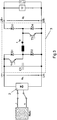
- Figure 3 shows the revised block diagrams of the overall system or the DC / DC converter with single-phase feed.
- Figure 4 and 5 represent the control structure of the DC / DC converter for single-phase network operation.
- the control unit 50 generates the control signals for the transistors T1 and T3 of the DC / DC converter 3.
- Input variables are the power specification P_specification, the maximum Voltage U_B_max on the side facing memory 4, that is, B side, of the DC / DC converter and the maximum current I_max of the DC / DC converter 3.
- the limit power determination unit 51 determines the power setpoint P_soll, taking into account the default power P_specification, the voltage U_B_max and the current I_max as well as depending on the current voltage u_B_ist.
- the setpoint power value P_soll is compared in the power regulator 52 with the measured actual value P_B_ist of the power on the B side of the DC / DC converter 3
- the power P_B_ist can be calculated from the voltage u_B_ist and the current i_ist taking into account the switch-on time of T4 and is fed to a controller 52, preferably designed as a linear controller, such as a PI controller, and then weighted with the reciprocal effective value of the A-side DC voltage U_A_eff. In this way, the effective value I_Soll_eff of the setpoint current is determined.
- the output variable of the block comprising the controller 52 including the weighting unit is the setpoint I_soll_eff of the effective current of the DC / DC converter. This is multiplied by the normalized and filtered voltage u_A_f (t) and given to the current regulator 53 as the setpoint i_soll (t). This determines the control signals of the transistors T1 and T3 taking into account the actual current i_ist and the actual voltages u_A_ist, u_B_ist.
- the signals U_A_eff and u_A_f (t) are determined in the signal filtering unit 54 from the actual voltage u_A_ist.
- the input variable here is the voltage u_A_ist, in particular the A-side voltage, of the DC / DC converter 3 that is present on the side facing the rectifier 2.
- the sign is changed as a function of the output voltage of the bandpass filter 40.
- the output signal of the bandpass filter 40 is in turn rectified and normalized on the basis of its effective value.
- the proposed control of the DC / DC converter 3 allows the absorption of an approximately sinusoidal mains current with a low distortion factor and an optimized one Power factor in all operating states, especially with output voltages U_B that are above and / or below the mains voltage amplitude.
- a bandpass-filtered value u_A_f (t), which is normalized with its effective value U_A_eff, is determined from the voltage present on the A side.
- the effective value U_A_eff, i.e. a low-pass filtered value, is thus also determined.
- the effective value U_A_eff is used to determine the effective value I_Soll_eff.
- the setpoint current value is determined by multiplying by the bandpass-filtered value and the signal u_A_f (t) normalized to its rms value.
Landscapes
- Engineering & Computer Science (AREA)
- Power Engineering (AREA)
- Rectifiers (AREA)
- Inverter Devices (AREA)
- Dc-Dc Converters (AREA)
Claims (12)
- Dispositif comprenant
une source de tension (1) située côté réseau,
un redresseur (2),
un accumulateur d'énergie (4) formé par des condensateurs,
au moins un onduleur, et
un convertisseur (3) CC/CC,
ledit accumulateur d'énergie (4) et ledit onduleur étant connectés en parallèle avec ledit convertisseur (3) CC/CC, lequel convertisseur (3) CC/CC est connecté à ladite source de tension (1) située côté réseau, par l'intermédiaire dudit redresseur (2),
lequel redresseur (2) est connecté à un enroulement secondaire couplé, par induction, à un conducteur primaire qui est prévu avec disposition stationnaire et est connecté à ladite source de tension,
ledit convertisseur (3) CC/CC incluant une unité de pilotage (50), laquelle unité de pilotage (50) inclut un régulateur de puissance (52) qui détermine une première valeur de consigne effective I_Soll_eff,
caractérisé par le fait que
l'unité de pilotage (50) inclut un régulateur de courant, sachant qu'une seconde valeur de consigne isoll(t), déterminée en multipliant un signal u_A_f(t) par la première valeur de consigne effective I_Soll_eff, peut être délivrée audit régulateur de courant, ledit signal u_A_f(t) étant déterminé, par filtrage passe-bande et par normalisation, à partir de la tension u_A(t) présente du côté du convertisseur (3) CC/CC qui pointe vers le redresseur (2). - Dispositif selon la revendication 1,
caractérisé par le fait que
le redresseur (2) est alimenté à partir d'une source de tension (1), par l'intermédiaire d'une connexion enfichable,
sachant que ladite connexion enfichable comporte une partie de connecteur enfichable Schuko et/ou que ladite source de tension (1) présente des valeurs comprises entre 100 volts et 300 volts, et entre 45 hertz et 65 hertz, en particulier 230 volts et 50 hertz. - Dispositif selon au moins l'une des revendications précédentes,
caractérisé par le fait que
l'onduleur respectif alimente un moteur électrique, notamment un moteur à courant triphasé, en particulier de façon telle que de l'énergie mécanique puisse être convertie en de l'énergie électrique lors du fonctionnement en mode générateur. - Dispositif selon au moins l'une des revendications précédentes,
caractérisé par le fait que
l'énergie excédentaire engendrée en mode générateur peut être délivrée à l'accumulateur d'énergie (4), et peut être stockée dans ce dernier. - Dispositif selon au moins l'une des revendications précédentes,
caractérisé par le fait que
le convertisseur (3) CC/CC remplit la fonction d'un organe de réglage affecté à la puissance délivrée par la source de tension (1) dudit dispositif, située côté réseau. - Dispositif selon au moins l'une des revendications précédentes,
caractérisé par le fait que
le convertisseur (3) CC/CC est conçu et agencé de telle sorte que la tension redressée côté réseau soit, en permanence ou au moins temporairement, inférieure ou égale à la tension se présentant du côté sortie. - Dispositif selon au moins l'une des revendications précédentes,
caractérisé par le fait que
le convertisseur (3) CC/CC présente une inductance branchée en série avec un premier interrupteur commandable, le courant de sortie du redresseur étant délivré à ce branchement en série,
sachant notamment qu'un interrupteur commandable supplémentaire est implanté du côté de ladite inductance qui pointe à l'opposé dudit premier interrupteur commandable, sachant qu'un premier branchement en série, constitué à partir dudit premier interrupteur commandable et d'une première diode, est alimenté par la tension alimentant le convertisseur (3) CC/CC côté entrée,
sachant qu'un second branchement en série, sur lequel est prévue la tension située côté sortie dudit convertisseur (3) CC/CC, est constitué à partir du second interrupteur commandable et d'une seconde diode. - Dispositif selon au moins l'une des revendications précédentes,
caractérisé par le fait que
le convertisseur (3) CC/CC est muni, côté entrée et côté sortie, d'un branchement respectif en série constitué à partir de deux interrupteurs commandables, les prises centrales des branchements en série étant connectées au moyen d'une inductance. - Dispositif selon au moins l'une des revendications précédentes,
caractérisé par le fait que
le courant circulant par l'inductance peut être détecté, et les valeurs détectées sont dirigées vers une électronique de signaux engendrant des signaux de pilotage qui sont dirigés vers l'interrupteur commandable considéré,
notamment de façon telle que la tension de sortie, engendrée sur le convertisseur (3) CC/CC côté sortie, excède la valeur de la tension appliquée audit convertisseur (3) CC/CC côté entrée,
ladite tension, appliquée audit convertisseur (3) CC/CC côté entrée, étant engendrée par un redresseur (2). - Dispositif selon au moins l'une des revendications précédentes,
caractérisé par le fait que
l'accumulateur d'énergie (4) est implanté, sur la partie mobile d'un axe de machine, de telle manière que le vent relatif, engendré au cours d'un mouvement dudit axe de machine, refroidisse ledit accumulateur d'énergie (4),
sachant notamment que le carter dudit accumulateur d'énergie (4) présente une réalisation à mode de protection élevée, en particulier avec étanchéité à l'eau et avec étanchéité à l'air. - Dispositif selon au moins l'une des revendications précédentes,
caractérisé par le fait que
l'accumulateur d'énergie (4) possède un grand dimensionnement tel que la part constitutive de l'énergie mécanique qui est présente au maximum dans ledit dispositif, notamment des énergies cinétique et potentielle, et qui peut être reconvertie en électricité, puisse être injectée dans ledit accumulateur d'énergie (4). - Procédé conçu pour faire fonctionner un dispositif,
ledit procédé incluant les étapes suivantes :- alimentation électrique d'un redresseur (2) à partir d'une source de tension qui alimente ledit redresseur (2) par l'intermédiaire d'un conducteur primaire couplé par induction, et d'un enroulement secondaire,- alimentation électrique en parallèle, par l'intermédiaire d'un convertisseur (3) CC/CC, d'un accumulateur d'énergie (4) et d'un onduleur, ledit convertisseur (3) CC/CC étant alimenté par ledit redresseur (2),- détermination d'une première valeur de consigne effective I_Soll_eff par l'intermédiaire d'un régulateur de puissance (52) intégré dans ledit convertisseur (3) CC/CC, un signal u_A_f(t) étant engendré, par filtrage passe-bande et par normalisation, à partir de la tension u_A(t) présente du côté dudit convertisseur (3) CC/CC qui pointe vers ledit redresseur (2),- délivrance, à un régulateur de courant, d'une seconde valeur de consigne i_soll(t) déterminée en multipliant ledit signal u_A_f(t) par ladite première valeur de consigne effective I_Soll_eff.
Applications Claiming Priority (3)
| Application Number | Priority Date | Filing Date | Title |
|---|---|---|---|
| DE102013005240 | 2013-03-27 | ||
| DE102013006964.5A DE102013006964B4 (de) | 2013-03-27 | 2013-04-23 | Vorrichtung mit Energiespeicher und Wechselrichter und Verfahren zum Betreiben einer Vorrichtung |
| PCT/EP2014/000402 WO2014154317A2 (fr) | 2013-03-27 | 2014-02-14 | Dispositif, en particulier machine ou installation, et procédé permettant de faire fonctionner un dispositif |
Publications (2)
| Publication Number | Publication Date |
|---|---|
| EP2979352A2 EP2979352A2 (fr) | 2016-02-03 |
| EP2979352B1 true EP2979352B1 (fr) | 2021-05-26 |
Family
ID=51519588
Family Applications (1)
| Application Number | Title | Priority Date | Filing Date |
|---|---|---|---|
| EP14706478.6A Active EP2979352B1 (fr) | 2013-03-27 | 2014-02-14 | Dispositif, en particulier machine ou installation, et procédé permettant de faire fonctionner un dispositif |
Country Status (3)
| Country | Link |
|---|---|
| EP (1) | EP2979352B1 (fr) |
| DE (1) | DE102013006964B4 (fr) |
| WO (1) | WO2014154317A2 (fr) |
Families Citing this family (7)
| Publication number | Priority date | Publication date | Assignee | Title |
|---|---|---|---|---|
| DE102014220165A1 (de) | 2014-10-06 | 2016-04-07 | Viastore Systems Gmbh | Regalbediengerät und Verfahren zum Steuern eines Regalbediengeräts |
| EP3516760A1 (fr) | 2016-09-22 | 2019-07-31 | SEW-Eurodrive GmbH & Co | Système et procédé de fonctionnement d'un système |
| EP3490132A1 (fr) * | 2017-11-28 | 2019-05-29 | Siemens Aktiengesellschaft | Onduleur à circuit intermédiaire doté de l'accouplement ciblé avec au moins un autre onduleur à circuit intermédiaire |
| EP3629469A1 (fr) | 2018-09-28 | 2020-04-01 | Siemens Aktiengesellschaft | Dispositif de transport à courroie ainsi que procédé de maintien d'une courroie d'un dispositif de transport à courroie |
| WO2021008727A2 (fr) * | 2019-07-18 | 2021-01-21 | Sew-Eurodrive Gmbh & Co. Kg | Procédé et système pour faire fonctionner un système comprenant un accumulateur d'énergie et une résistance |
| DE102020003799A1 (de) * | 2019-07-18 | 2021-01-21 | Sew-Eurodrive Gmbh & Co Kg | Verfahren zum Betreiben eines Systems und System mit einem Versorgungsmodul, einem Wechselrichter, einem Energiespeicher und einem Netzteil |
| CN114013899A (zh) * | 2021-10-16 | 2022-02-08 | 无锡泰田智能装备科技有限公司 | 一种智能工厂用货架分料装置 |
Citations (2)
| Publication number | Priority date | Publication date | Assignee | Title |
|---|---|---|---|---|
| DE19546421C1 (de) * | 1995-12-12 | 1996-10-24 | Siemens Ag | Batterieankoppelvorrichtung |
| US20020093310A1 (en) * | 2000-11-16 | 2002-07-18 | Tatsuya Uematsu | Power supply circuit of mobile unit supplied with power without contact, and mobile unit |
Family Cites Families (13)
| Publication number | Priority date | Publication date | Assignee | Title |
|---|---|---|---|---|
| US5734258A (en) | 1996-06-03 | 1998-03-31 | General Electric Company | Bidirectional buck boost converter |
| JP4544884B2 (ja) * | 2004-03-18 | 2010-09-15 | 東芝エレベータ株式会社 | エレベータ制御装置 |
| DE102005042321A1 (de) | 2005-09-06 | 2007-03-08 | Siemens Ag | Weitspannungs-Umrichter |
| DE102007026012B4 (de) | 2006-07-10 | 2024-01-25 | Heidelberger Druckmaschinen Ag | Gesteuerter Energieverbrauch von elektrischen Antrieben in Maschinen |
| DE502007001146D1 (de) * | 2007-11-26 | 2009-09-03 | Trumpf Sachsen Gmbh | Verfahren zum Auslagern, Verfahren zum Einlagern und Verfahren zum Handling von Lagergut an einem Lager sowie Lageranordnungen zur Realisierung der genannten Verfahren |
| DE102008034887B4 (de) | 2008-07-26 | 2025-08-14 | Mercedes-Benz Group AG | Kühlvorrichtung für eine Batterie und Kraftfahrzeug mit einer Batterie |
| JP2010180003A (ja) * | 2009-02-04 | 2010-08-19 | Saitama Univ | エレベータ電源装置 |
| DE102010007275B4 (de) | 2010-02-08 | 2020-03-05 | Sew-Eurodrive Gmbh & Co Kg | Antriebssystem und Verfahren zum Betreiben eines Antriebssystems |
| DE102010032936B4 (de) * | 2010-07-30 | 2022-05-25 | Sew-Eurodrive Gmbh & Co Kg | Anordnung zum Kühlen von Wärme erzeugenden elektrischen Bauelementen, Kondensatorbaugruppe und Herstellverfahren für eine Anordnung |
| JP2012157083A (ja) | 2011-01-21 | 2012-08-16 | Nissan Motor Co Ltd | 車輪給電装置 |
| DE102011011428B4 (de) | 2011-02-16 | 2013-05-23 | Sew-Eurodrive Gmbh & Co. Kg | Vorrichtung, insbesondere Elektrofahrzeug, Hubwerk, Regalbediengerät mit Hubwerk oder Gabelstapler, mit Energiespeicher |
| JP5291763B2 (ja) * | 2011-06-24 | 2013-09-18 | ファナック株式会社 | エネルギー蓄積部を有するモータ駆動装置 |
| DK2578876T3 (da) | 2011-10-05 | 2014-08-25 | Siemens Ag | Pitchsystem til et vindenergianlæg og fremgangsmåde til drift af et pitchsystem |
-
2013
- 2013-04-23 DE DE102013006964.5A patent/DE102013006964B4/de active Active
-
2014
- 2014-02-14 WO PCT/EP2014/000402 patent/WO2014154317A2/fr not_active Ceased
- 2014-02-14 EP EP14706478.6A patent/EP2979352B1/fr active Active
Patent Citations (2)
| Publication number | Priority date | Publication date | Assignee | Title |
|---|---|---|---|---|
| DE19546421C1 (de) * | 1995-12-12 | 1996-10-24 | Siemens Ag | Batterieankoppelvorrichtung |
| US20020093310A1 (en) * | 2000-11-16 | 2002-07-18 | Tatsuya Uematsu | Power supply circuit of mobile unit supplied with power without contact, and mobile unit |
Also Published As
| Publication number | Publication date |
|---|---|
| WO2014154317A3 (fr) | 2015-05-07 |
| WO2014154317A2 (fr) | 2014-10-02 |
| DE102013006964B4 (de) | 2024-01-25 |
| DE102013006964A1 (de) | 2014-10-02 |
| EP2979352A2 (fr) | 2016-02-03 |
Similar Documents
| Publication | Publication Date | Title |
|---|---|---|
| EP2979352B1 (fr) | Dispositif, en particulier machine ou installation, et procédé permettant de faire fonctionner un dispositif | |
| EP2411240B1 (fr) | Systeme d'entrainement electrique, son procédé de fonctionnement | |
| EP2391522B1 (fr) | Convertisseur cc/cc et convertisseur ca/cc | |
| EP2812989B1 (fr) | Système d'entraînement doté d'un accumulateur d'énergie et procédé de fonctionnement d'un système d'entraînement | |
| WO2014118000A2 (fr) | Système de transmission d'énergie | |
| DE112015001920T5 (de) | Stromquellenvorrichtung | |
| DE102016101473A1 (de) | Motorantrieb, einen kondensator verwendend | |
| DE102017006819A1 (de) | System und Verfahren zum Betreiben eines Systems | |
| DE102020205494A1 (de) | Elektrisches Leistungsumwandlungssystem für ein Fahrzeug und Steuerungsverfahren dafür | |
| DE2752600C2 (de) | Verfahren und Schaltungsanordnung zur Steuerung einer umrichtergespeisten Asynchronmaschine | |
| EP3763026B1 (fr) | Procédé d'opération d'un système d'entrainement électrique avec accumulateur d'énergie et dispositif pour réaliser ce procédé | |
| EP3642932A1 (fr) | Dispositif et procédé pour générer et injecter activement de la puissance réactive dans un système de transmission inductif | |
| EP2820752B1 (fr) | Redresseur semi-active avec réglage vectoriel de puissance reactive | |
| EP2664049B1 (fr) | Dispositif d'alimentation en énergie électrique d'un réseau d'alimentation en énergie | |
| DE102011110197A1 (de) | System, insbesondere lokales Energieverteilungssystem, mit einem Zwischenkreis, Verfahren zur Regelung des Energieflusses in einem System und verwendung von in verschiedenen Gehäusen angeordneten Stellern eines Systems | |
| WO2017008927A1 (fr) | Dispositif et procédé de transmission inductive d'énergie inductive à des consommateurs électriques mobiles | |
| EP2763276A1 (fr) | Convertisseur et procédé de fonctionnement d'un tel système | |
| DE102007027221A1 (de) | Frequenzumrichter sowie Verfahren zum Betreiben eines Elektromotors mit einem solchen Frequenzumrichter | |
| EP2909925B1 (fr) | Accumulateur d'énergie dans un circuit intermédiaire cc d'un convertisseur d'entraînement alimenté par un redresseur et un convertisseur élevateur/abaisseur | |
| EP3488520A1 (fr) | Système convertisseur et procédé de fonctionnement d'un système convertisseur | |
| EP1619781B1 (fr) | Circuit pour un convertisseur | |
| WO2010088979A1 (fr) | Procédé de régulation d'un convertisseur côté réseau à commutation automatique dans un convertisseur indirect de tension | |
| DE102011009933B4 (de) | Elektrofahrzeug und Verfahren zum Betreiben eines Elektrofahrzeugs | |
| EP3365963B1 (fr) | Installation, comportant un réseau, un filtre et plusieurs dispositifs d'entraînement | |
| EP2975747B1 (fr) | Amélioration d'une tension d'une liaison d'alimentation en courant |
Legal Events
| Date | Code | Title | Description |
|---|---|---|---|
| PUAI | Public reference made under article 153(3) epc to a published international application that has entered the european phase |
Free format text: ORIGINAL CODE: 0009012 |
|
| 17P | Request for examination filed |
Effective date: 20151109 |
|
| AK | Designated contracting states |
Kind code of ref document: A2 Designated state(s): AL AT BE BG CH CY CZ DE DK EE ES FI FR GB GR HR HU IE IS IT LI LT LU LV MC MK MT NL NO PL PT RO RS SE SI SK SM TR |
|
| AX | Request for extension of the european patent |
Extension state: BA ME |
|
| DAX | Request for extension of the european patent (deleted) | ||
| STAA | Information on the status of an ep patent application or granted ep patent |
Free format text: STATUS: EXAMINATION IS IN PROGRESS |
|
| 17Q | First examination report despatched |
Effective date: 20190102 |
|
| GRAP | Despatch of communication of intention to grant a patent |
Free format text: ORIGINAL CODE: EPIDOSNIGR1 |
|
| STAA | Information on the status of an ep patent application or granted ep patent |
Free format text: STATUS: GRANT OF PATENT IS INTENDED |
|
| INTG | Intention to grant announced |
Effective date: 20201026 |
|
| GRAS | Grant fee paid |
Free format text: ORIGINAL CODE: EPIDOSNIGR3 |
|
| GRAJ | Information related to disapproval of communication of intention to grant by the applicant or resumption of examination proceedings by the epo deleted |
Free format text: ORIGINAL CODE: EPIDOSDIGR1 |
|
| GRAL | Information related to payment of fee for publishing/printing deleted |
Free format text: ORIGINAL CODE: EPIDOSDIGR3 |
|
| STAA | Information on the status of an ep patent application or granted ep patent |
Free format text: STATUS: EXAMINATION IS IN PROGRESS |
|
| GRAP | Despatch of communication of intention to grant a patent |
Free format text: ORIGINAL CODE: EPIDOSNIGR1 |
|
| STAA | Information on the status of an ep patent application or granted ep patent |
Free format text: STATUS: GRANT OF PATENT IS INTENDED |
|
| INTC | Intention to grant announced (deleted) | ||
| INTG | Intention to grant announced |
Effective date: 20210319 |
|
| GRAA | (expected) grant |
Free format text: ORIGINAL CODE: 0009210 |
|
| STAA | Information on the status of an ep patent application or granted ep patent |
Free format text: STATUS: THE PATENT HAS BEEN GRANTED |
|
| AK | Designated contracting states |
Kind code of ref document: B1 Designated state(s): AL AT BE BG CH CY CZ DE DK EE ES FI FR GB GR HR HU IE IS IT LI LT LU LV MC MK MT NL NO PL PT RO RS SE SI SK SM TR |
|
| REG | Reference to a national code |
Ref country code: GB Ref legal event code: FG4D Free format text: NOT ENGLISH |
|
| REG | Reference to a national code |
Ref country code: CH Ref legal event code: EP |
|
| REG | Reference to a national code |
Ref country code: AT Ref legal event code: REF Ref document number: 1397237 Country of ref document: AT Kind code of ref document: T Effective date: 20210615 |
|
| REG | Reference to a national code |
Ref country code: DE Ref legal event code: R096 Ref document number: 502014015615 Country of ref document: DE |
|
| REG | Reference to a national code |
Ref country code: IE Ref legal event code: FG4D Free format text: LANGUAGE OF EP DOCUMENT: GERMAN |
|
| REG | Reference to a national code |
Ref country code: LT Ref legal event code: MG9D |
|
| PG25 | Lapsed in a contracting state [announced via postgrant information from national office to epo] |
Ref country code: BG Free format text: LAPSE BECAUSE OF FAILURE TO SUBMIT A TRANSLATION OF THE DESCRIPTION OR TO PAY THE FEE WITHIN THE PRESCRIBED TIME-LIMIT Effective date: 20210826 Ref country code: FI Free format text: LAPSE BECAUSE OF FAILURE TO SUBMIT A TRANSLATION OF THE DESCRIPTION OR TO PAY THE FEE WITHIN THE PRESCRIBED TIME-LIMIT Effective date: 20210526 Ref country code: LT Free format text: LAPSE BECAUSE OF FAILURE TO SUBMIT A TRANSLATION OF THE DESCRIPTION OR TO PAY THE FEE WITHIN THE PRESCRIBED TIME-LIMIT Effective date: 20210526 Ref country code: HR Free format text: LAPSE BECAUSE OF FAILURE TO SUBMIT A TRANSLATION OF THE DESCRIPTION OR TO PAY THE FEE WITHIN THE PRESCRIBED TIME-LIMIT Effective date: 20210526 |
|
| REG | Reference to a national code |
Ref country code: NL Ref legal event code: MP Effective date: 20210526 |
|
| PG25 | Lapsed in a contracting state [announced via postgrant information from national office to epo] |
Ref country code: GR Free format text: LAPSE BECAUSE OF FAILURE TO SUBMIT A TRANSLATION OF THE DESCRIPTION OR TO PAY THE FEE WITHIN THE PRESCRIBED TIME-LIMIT Effective date: 20210827 Ref country code: LV Free format text: LAPSE BECAUSE OF FAILURE TO SUBMIT A TRANSLATION OF THE DESCRIPTION OR TO PAY THE FEE WITHIN THE PRESCRIBED TIME-LIMIT Effective date: 20210526 Ref country code: IS Free format text: LAPSE BECAUSE OF FAILURE TO SUBMIT A TRANSLATION OF THE DESCRIPTION OR TO PAY THE FEE WITHIN THE PRESCRIBED TIME-LIMIT Effective date: 20210926 Ref country code: SE Free format text: LAPSE BECAUSE OF FAILURE TO SUBMIT A TRANSLATION OF THE DESCRIPTION OR TO PAY THE FEE WITHIN THE PRESCRIBED TIME-LIMIT Effective date: 20210526 Ref country code: RS Free format text: LAPSE BECAUSE OF FAILURE TO SUBMIT A TRANSLATION OF THE DESCRIPTION OR TO PAY THE FEE WITHIN THE PRESCRIBED TIME-LIMIT Effective date: 20210526 Ref country code: PL Free format text: LAPSE BECAUSE OF FAILURE TO SUBMIT A TRANSLATION OF THE DESCRIPTION OR TO PAY THE FEE WITHIN THE PRESCRIBED TIME-LIMIT Effective date: 20210526 Ref country code: NO Free format text: LAPSE BECAUSE OF FAILURE TO SUBMIT A TRANSLATION OF THE DESCRIPTION OR TO PAY THE FEE WITHIN THE PRESCRIBED TIME-LIMIT Effective date: 20210826 Ref country code: PT Free format text: LAPSE BECAUSE OF FAILURE TO SUBMIT A TRANSLATION OF THE DESCRIPTION OR TO PAY THE FEE WITHIN THE PRESCRIBED TIME-LIMIT Effective date: 20210927 |
|
| PG25 | Lapsed in a contracting state [announced via postgrant information from national office to epo] |
Ref country code: NL Free format text: LAPSE BECAUSE OF FAILURE TO SUBMIT A TRANSLATION OF THE DESCRIPTION OR TO PAY THE FEE WITHIN THE PRESCRIBED TIME-LIMIT Effective date: 20210526 |
|
| PG25 | Lapsed in a contracting state [announced via postgrant information from national office to epo] |
Ref country code: SK Free format text: LAPSE BECAUSE OF FAILURE TO SUBMIT A TRANSLATION OF THE DESCRIPTION OR TO PAY THE FEE WITHIN THE PRESCRIBED TIME-LIMIT Effective date: 20210526 Ref country code: SM Free format text: LAPSE BECAUSE OF FAILURE TO SUBMIT A TRANSLATION OF THE DESCRIPTION OR TO PAY THE FEE WITHIN THE PRESCRIBED TIME-LIMIT Effective date: 20210526 Ref country code: CZ Free format text: LAPSE BECAUSE OF FAILURE TO SUBMIT A TRANSLATION OF THE DESCRIPTION OR TO PAY THE FEE WITHIN THE PRESCRIBED TIME-LIMIT Effective date: 20210526 Ref country code: EE Free format text: LAPSE BECAUSE OF FAILURE TO SUBMIT A TRANSLATION OF THE DESCRIPTION OR TO PAY THE FEE WITHIN THE PRESCRIBED TIME-LIMIT Effective date: 20210526 Ref country code: DK Free format text: LAPSE BECAUSE OF FAILURE TO SUBMIT A TRANSLATION OF THE DESCRIPTION OR TO PAY THE FEE WITHIN THE PRESCRIBED TIME-LIMIT Effective date: 20210526 Ref country code: ES Free format text: LAPSE BECAUSE OF FAILURE TO SUBMIT A TRANSLATION OF THE DESCRIPTION OR TO PAY THE FEE WITHIN THE PRESCRIBED TIME-LIMIT Effective date: 20210526 Ref country code: RO Free format text: LAPSE BECAUSE OF FAILURE TO SUBMIT A TRANSLATION OF THE DESCRIPTION OR TO PAY THE FEE WITHIN THE PRESCRIBED TIME-LIMIT Effective date: 20210526 |
|
| REG | Reference to a national code |
Ref country code: DE Ref legal event code: R097 Ref document number: 502014015615 Country of ref document: DE |
|
| PLBE | No opposition filed within time limit |
Free format text: ORIGINAL CODE: 0009261 |
|
| STAA | Information on the status of an ep patent application or granted ep patent |
Free format text: STATUS: NO OPPOSITION FILED WITHIN TIME LIMIT |
|
| 26N | No opposition filed |
Effective date: 20220301 |
|
| PG25 | Lapsed in a contracting state [announced via postgrant information from national office to epo] |
Ref country code: IS Free format text: LAPSE BECAUSE OF FAILURE TO SUBMIT A TRANSLATION OF THE DESCRIPTION OR TO PAY THE FEE WITHIN THE PRESCRIBED TIME-LIMIT Effective date: 20210926 Ref country code: AL Free format text: LAPSE BECAUSE OF FAILURE TO SUBMIT A TRANSLATION OF THE DESCRIPTION OR TO PAY THE FEE WITHIN THE PRESCRIBED TIME-LIMIT Effective date: 20210526 |
|
| PG25 | Lapsed in a contracting state [announced via postgrant information from national office to epo] |
Ref country code: IT Free format text: LAPSE BECAUSE OF FAILURE TO SUBMIT A TRANSLATION OF THE DESCRIPTION OR TO PAY THE FEE WITHIN THE PRESCRIBED TIME-LIMIT Effective date: 20210526 |
|
| PG25 | Lapsed in a contracting state [announced via postgrant information from national office to epo] |
Ref country code: MC Free format text: LAPSE BECAUSE OF FAILURE TO SUBMIT A TRANSLATION OF THE DESCRIPTION OR TO PAY THE FEE WITHIN THE PRESCRIBED TIME-LIMIT Effective date: 20210526 |
|
| REG | Reference to a national code |
Ref country code: CH Ref legal event code: PL |
|
| REG | Reference to a national code |
Ref country code: BE Ref legal event code: MM Effective date: 20220228 |
|
| GBPC | Gb: european patent ceased through non-payment of renewal fee |
Effective date: 20220214 |
|
| PG25 | Lapsed in a contracting state [announced via postgrant information from national office to epo] |
Ref country code: LU Free format text: LAPSE BECAUSE OF NON-PAYMENT OF DUE FEES Effective date: 20220214 |
|
| PG25 | Lapsed in a contracting state [announced via postgrant information from national office to epo] |
Ref country code: LI Free format text: LAPSE BECAUSE OF NON-PAYMENT OF DUE FEES Effective date: 20220228 Ref country code: IE Free format text: LAPSE BECAUSE OF NON-PAYMENT OF DUE FEES Effective date: 20220214 Ref country code: GB Free format text: LAPSE BECAUSE OF NON-PAYMENT OF DUE FEES Effective date: 20220214 Ref country code: CH Free format text: LAPSE BECAUSE OF NON-PAYMENT OF DUE FEES Effective date: 20220228 |
|
| PG25 | Lapsed in a contracting state [announced via postgrant information from national office to epo] |
Ref country code: BE Free format text: LAPSE BECAUSE OF NON-PAYMENT OF DUE FEES Effective date: 20220228 |
|
| REG | Reference to a national code |
Ref country code: AT Ref legal event code: MM01 Ref document number: 1397237 Country of ref document: AT Kind code of ref document: T Effective date: 20220214 |
|
| PG25 | Lapsed in a contracting state [announced via postgrant information from national office to epo] |
Ref country code: AT Free format text: LAPSE BECAUSE OF NON-PAYMENT OF DUE FEES Effective date: 20220214 |
|
| PG25 | Lapsed in a contracting state [announced via postgrant information from national office to epo] |
Ref country code: HU Free format text: LAPSE BECAUSE OF FAILURE TO SUBMIT A TRANSLATION OF THE DESCRIPTION OR TO PAY THE FEE WITHIN THE PRESCRIBED TIME-LIMIT; INVALID AB INITIO Effective date: 20140214 |
|
| PG25 | Lapsed in a contracting state [announced via postgrant information from national office to epo] |
Ref country code: MK Free format text: LAPSE BECAUSE OF FAILURE TO SUBMIT A TRANSLATION OF THE DESCRIPTION OR TO PAY THE FEE WITHIN THE PRESCRIBED TIME-LIMIT Effective date: 20210526 Ref country code: CY Free format text: LAPSE BECAUSE OF FAILURE TO SUBMIT A TRANSLATION OF THE DESCRIPTION OR TO PAY THE FEE WITHIN THE PRESCRIBED TIME-LIMIT Effective date: 20210526 |
|
| PG25 | Lapsed in a contracting state [announced via postgrant information from national office to epo] |
Ref country code: TR Free format text: LAPSE BECAUSE OF FAILURE TO SUBMIT A TRANSLATION OF THE DESCRIPTION OR TO PAY THE FEE WITHIN THE PRESCRIBED TIME-LIMIT Effective date: 20210526 |
|
| PG25 | Lapsed in a contracting state [announced via postgrant information from national office to epo] |
Ref country code: MT Free format text: LAPSE BECAUSE OF FAILURE TO SUBMIT A TRANSLATION OF THE DESCRIPTION OR TO PAY THE FEE WITHIN THE PRESCRIBED TIME-LIMIT Effective date: 20210526 |
|
| PGFP | Annual fee paid to national office [announced via postgrant information from national office to epo] |
Ref country code: FR Payment date: 20251231 Year of fee payment: 13 |
|
| PGFP | Annual fee paid to national office [announced via postgrant information from national office to epo] |
Ref country code: DE Payment date: 20260228 Year of fee payment: 13 |