EP2979659A2 - Procédés d'amélioration des fuites haute fréquence de générateurs électrochirurgicaux - Google Patents
Procédés d'amélioration des fuites haute fréquence de générateurs électrochirurgicaux Download PDFInfo
- Publication number
- EP2979659A2 EP2979659A2 EP15179277.7A EP15179277A EP2979659A2 EP 2979659 A2 EP2979659 A2 EP 2979659A2 EP 15179277 A EP15179277 A EP 15179277A EP 2979659 A2 EP2979659 A2 EP 2979659A2
- Authority
- EP
- European Patent Office
- Prior art keywords
- electrosurgical generator
- contact
- capacitor
- electrically coupled
- switching member
- Prior art date
- Legal status (The legal status is an assumption and is not a legal conclusion. Google has not performed a legal analysis and makes no representation as to the accuracy of the status listed.)
- Granted
Links
Images


Classifications
-
- A—HUMAN NECESSITIES
- A61—MEDICAL OR VETERINARY SCIENCE; HYGIENE
- A61B—DIAGNOSIS; SURGERY; IDENTIFICATION
- A61B18/00—Surgical instruments, devices or methods for transferring non-mechanical forms of energy to or from the body
- A61B18/04—Surgical instruments, devices or methods for transferring non-mechanical forms of energy to or from the body by heating
- A61B18/12—Surgical instruments, devices or methods for transferring non-mechanical forms of energy to or from the body by heating by passing a current through the tissue to be heated, e.g. high-frequency current
- A61B18/1206—Generators therefor
- A61B18/1233—Generators therefor with circuits for assuring patient safety
-
- A—HUMAN NECESSITIES
- A61—MEDICAL OR VETERINARY SCIENCE; HYGIENE
- A61F—FILTERS IMPLANTABLE INTO BLOOD VESSELS; PROSTHESES; DEVICES PROVIDING PATENCY TO, OR PREVENTING COLLAPSING OF, TUBULAR STRUCTURES OF THE BODY, e.g. STENTS; ORTHOPAEDIC, NURSING OR CONTRACEPTIVE DEVICES; FOMENTATION; TREATMENT OR PROTECTION OF EYES OR EARS; BANDAGES, DRESSINGS OR ABSORBENT PADS; FIRST-AID KITS
- A61F7/00—Heating or cooling appliances for medical or therapeutic treatment of the human body
- A61F7/007—Heating or cooling appliances for medical or therapeutic treatment of the human body characterised by electric heating
-
- H—ELECTRICITY
- H05—ELECTRIC TECHNIQUES NOT OTHERWISE PROVIDED FOR
- H05K—PRINTED CIRCUITS; CASINGS OR CONSTRUCTIONAL DETAILS OF ELECTRIC APPARATUS; MANUFACTURE OF ASSEMBLAGES OF ELECTRICAL COMPONENTS
- H05K1/00—Printed circuits
- H05K1/02—Details
- H05K1/11—Printed elements for providing electric connections to or between printed circuits
-
- H—ELECTRICITY
- H05—ELECTRIC TECHNIQUES NOT OTHERWISE PROVIDED FOR
- H05K—PRINTED CIRCUITS; CASINGS OR CONSTRUCTIONAL DETAILS OF ELECTRIC APPARATUS; MANUFACTURE OF ASSEMBLAGES OF ELECTRICAL COMPONENTS
- H05K1/00—Printed circuits
- H05K1/18—Printed circuits structurally associated with non-printed electric components
-
- A—HUMAN NECESSITIES
- A61—MEDICAL OR VETERINARY SCIENCE; HYGIENE
- A61B—DIAGNOSIS; SURGERY; IDENTIFICATION
- A61B18/00—Surgical instruments, devices or methods for transferring non-mechanical forms of energy to or from the body
- A61B18/04—Surgical instruments, devices or methods for transferring non-mechanical forms of energy to or from the body by heating
- A61B18/12—Surgical instruments, devices or methods for transferring non-mechanical forms of energy to or from the body by heating by passing a current through the tissue to be heated, e.g. high-frequency current
- A61B18/1206—Generators therefor
- A61B2018/1286—Generators therefor having a specific transformer
-
- G—PHYSICS
- G05—CONTROLLING; REGULATING
- G05B—CONTROL OR REGULATING SYSTEMS IN GENERAL; FUNCTIONAL ELEMENTS OF SUCH SYSTEMS; MONITORING OR TESTING ARRANGEMENTS FOR SUCH SYSTEMS OR ELEMENTS
- G05B2219/00—Program-control systems
- G05B2219/30—Nc systems
- G05B2219/32—Operator till task planning
- G05B2219/32014—Augmented reality assists operator in maintenance, repair, programming, assembly, use of head mounted display with 2-D 3-D display and voice feedback, voice and gesture command
-
- H—ELECTRICITY
- H05—ELECTRIC TECHNIQUES NOT OTHERWISE PROVIDED FOR
- H05K—PRINTED CIRCUITS; CASINGS OR CONSTRUCTIONAL DETAILS OF ELECTRIC APPARATUS; MANUFACTURE OF ASSEMBLAGES OF ELECTRICAL COMPONENTS
- H05K1/00—Printed circuits
- H05K1/16—Printed circuits incorporating printed electric components, e.g. printed resistors, capacitors or inductors
- H05K1/162—Printed circuits incorporating printed electric components, e.g. printed resistors, capacitors or inductors incorporating printed capacitors
-
- H—ELECTRICITY
- H05—ELECTRIC TECHNIQUES NOT OTHERWISE PROVIDED FOR
- H05K—PRINTED CIRCUITS; CASINGS OR CONSTRUCTIONAL DETAILS OF ELECTRIC APPARATUS; MANUFACTURE OF ASSEMBLAGES OF ELECTRICAL COMPONENTS
- H05K2201/00—Indexing scheme relating to printed circuits covered by H05K1/00
- H05K2201/10—Details of components or other objects attached to or integrated in a printed circuit board
- H05K2201/10007—Types of components
- H05K2201/10015—Non-printed capacitor
Definitions
- the present disclosure relates to radiofrequency amplifiers that use phase-shifted full bridge resonant inverters. Particularly, the present disclosure is directed to reducing common mode currents and high frequency leakage in radiofrequency amplifiers.
- Electrosurgery involves application of high radio frequency electrical current to a surgical site to cut, ablate, coagulate or seal tissue.
- a source or active electrode delivers radio frequency energy from the electro surgical generator to the tissue and a return electrode carries the current back to the generator.
- the source electrode is typically part of the surgical instrument held by the surgeon and applied to the tissue to be treated and the return electrode is placed remotely from the active electrode to carry the current back to the generator.
- bipolar electrosurgery one of the electrodes of the hand-held instrument functions as the active electrode and the other as the return electrode.
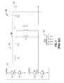
- Fig. 1 is an example of a prior art electrosurgical generator that uses a phase-shifted full bridge resonant inverter to generate the electrosurgical energy needed to perform the electrosurgical procedure.
- the generator 100 includes a resonant inverter circuit 102 and a pulse width modulation (PWM) controller 108.
- the resonant inverter circuit 102 includes an H-bridge 104 and a tank 106.
- tank 106 a series capacitor C S2 is placed in series with the secondary of the transformer T 1 to prevent DC current from flowing into the output of the active terminal 110 and possibly harming a patient or an end user.
- the presence of capacitor C S2 introduces a slight imbalance in the charge and high frequency output that may contribute to the potential flow of common mode currents and high frequency leakage current imbalances while under load.
- an electrosurgical generator includes an H-bridge and a tank driven by the H-bridge.
- the tank includes a transformer having a primary winding and a secondary winding which includes a first coil and a second coil.
- the tank also includes a capacitor connected in series between the first coil and the second coil.
- a controller is configured to drive the H-bridge.
- the electrosurgical generator also includes a charge drain electrically coupled to the capacitor.
- the charge drain includes a switching member which may be any conventional switch or a relay.
- a controller may control the switching member wherein the controller closes the switching member when the electrosurgical generator is inactive and opens the switching member when the electrosurgical generator is active.
- the charge drain may also include a resistor or a positive temperature coefficient thermistor or resettable fuse.
- a printed circuit board for use in an electrosurgical generator.
- the printed circuit board includes a plurality of contacts configured to receive a secondary winding of a transformer.
- the plurality of contacts include: a first contact configured to be electrically coupled to an active terminal; a second contact configured to be electrically coupled to a return terminal; a third contact; and a fourth contact.
- the printed circuit board also includes a capacitor integrated into the printed circuit board. The capacitor is electrically coupled to the third contact and the fourth contact.
- the third contact and the fourth contact are configured to be electrically coupled to a center tap of the transformer.
- a phrase in the form "A/B” means A or B.
- a phrase in the form "A and/or B” means "(A), (B), or (A and B)”.
- a phrase in the form "at least one of A, B, or C” means "(A), (B), (C), (A and B), (A and C), (B and C), or (A, B and C)".
- the term "generator” may refer to a device capable of providing energy. Such device may include a power source and an electrical circuit capable of modifying the energy outputted by the power source to output energy having a desired intensity, frequency, and/or waveform.
- the systems described herein may also utilize one or more controllers to receive various information and transform the received information to generate an output.
- the controller may include any type of computing device, computational circuit, or any type of processor or processing circuit capable of executing a series of instructions that are stored in a memory.
- the controller may include multiple processors and/or multicore central processing units (CPUs) and may include any type of processor, such as a microprocessor, digital signal processor, microcontroller, or the like.
- the controller may also include a memory to store data and/or algorithms to perform a series of instructions.
- any of the herein described data and/or algorithms may be contained on one or more machine-readable media or memory.
- the term "memory" may include a mechanism that provides (e.g., stores and/or transmits) information in a form readable by a machine such as a processor, computer, or a digital processing device.
- a memory may include a read only memory (ROM), random access memory (RAM), magnetic disk storage media, optical storage media, flash memory devices, or any other volatile or non-volatile memory storage device.
- Code or instructions contained thereon can be represented by carrier wave signals, infrared signals, digital signals, and by other like signals.
- the present disclosure is directed to an electrosurgical generator that employs a phase-shifted full bridge resonant inverter having a tank topology and an H-bridge.
- a capacitor is placed at a center tap on the secondary side of a transformer in the tank topology.
- the capacitor may be a discrete component or it may be integrated into a PCB.
- an electrosurgical generator in accordance with an embodiment of the present disclosure is shown generally as 200.
- the generator 200 includes suitable input controls (e.g., buttons, activators, switches, touch screen, etc.) for controlling the generator 200.
- the generator 200 may include one or more display screens (not shown) for providing the user with variety of output information (e.g., intensity settings, treatment complete indicators, etc.).
- the controls allow the user to adjust power of the RF energy, waveform, as well as the level of maximum arc energy allowed which varies depending on desired tissue effects and other parameters to achieve the desired waveform suitable for a particular task, e.g., coagulating, tissue sealing, intensity setting, etc.
- An instrument that may be connected to the generator 200 may also include a plurality of input controls that may be redundant with certain input controls of the generator 200. Placing the input controls at the instrument allows for easier and faster modification of RF energy parameters during the surgical procedure without requiring interaction with the generator 200.
- the generator 200 may include a plurality of connectors to accommodate various types of electrosurgical instruments. Further, the generator 200 may operate in monopolar or bipolar modes by including a switching mechanism (e.g., relays) to switch the supply of RF energy between the connectors.
- a switching mechanism e.g., relays
- the generator 200 includes a resonant inverter circuit 202 and a pulse width modulation (PWM) controller 204.
- the resonant inverter circuit 202 includes an H-bridge 206 having FETs Q1, Q2, Q3, and Q4 and a tank 208.
- the PWM controller 204 includes a processor 210 and a memory 212.
- the H-bridge 206 is supplied with a positive high voltage direct current (+HVDC).
- the tank 208 is driven in a full-bridge configuration by the active FET switches Q1, Q2, Q3 and Q4.
- the PWM controller 208 supplies phase-shifted PWM timing signals to FET switches Q1, Q2, Q3 and Q4 as shown in Fig. 2 .
- FETs Q1 and Q2 provide a voltage V S1 to the tank 208 and FETs Q3 and Q4 provide a voltage V S2 to the tank 208.
- the tank 208 outputs electrosurgical energy to an instrument (not shown) via active terminal 214.
- the active terminal 214 provides either continuous or pulsed sinusoidal waveforms of high RF energy.
- the active terminal 214 is configured to provide a plurality of waveforms having various duty cycles, peak voltages, crest factors, and other suitable parameters. Certain types of waveforms are suitable for specific electrosurgical modes. For instance, the active terminal 214 may provide a 100% duty cycle sinusoidal waveform in cut mode, which is best suited for ablating, fusing and dissecting tissue and a 1-25% duty cycle waveform in coagulation mode, which is best used for cauterizing tissue to stop bleeding.
- a return terminal 216 is coupled to a return pad (not shown) for monopolar procedures. Alternatively, the return terminal 216 is electrically coupled to a return electrode (not shown) on an instrument.
- the tank 208 includes a transformer 218 that is used to provide the desired voltage output as well as isolate the patient from the generator.
- the transformer 218 includes a primary winding 220 and a secondary winding 222.
- the secondary winding 222 is a split output winding that includes a first coil 222A and a second coil 222B.
- a capacitor 224 is placed at a center tap of the transformer 218. Specifically, the capacitor 224 is placed in series between the first coil 222A and the second coil 222B. As shown in Fig. 2 , the capacitor 224 is placed across the common mode plane (represented by line X-X).
- capacitor 224 By placing the capacitor 224 in series between the first and second coils 222A, 222B across the common mode plane, a current or charge imbalance between terminals 214 and 216 is mitigated thus reducing any common mode currents and high frequency leakage. Also, the presence of the capacitor 224 prevents DC current from flowing into the output of the active terminal 214 and possibly harming a patient or an end user.
- a charge drain 226 is placed in parallel with the capacitor 224 to prevent the build-up of charge on the capacitor 224.
- the charge drain 226 includes a switch 228.
- the switch 228 may be any conventional switch or relay.
- the switch 228 is normally closed when the generator 200 is inactive and open when the generator 200 is active.
- the switch 228 may be controlled by a PWM controller 204, another controller (not shown), or a sensor (not shown) that detects whether the generator 200 is active or inactive.
- Fig. 3B includes a charge drain resistor 230 to assist in the discharge of capacitor 224.
- Fig. 3C substitutes the charge drain resistor 230 of Fig. 3B with a positive temperature coefficient (PTC) thermistor or resettable fuse 232.
- PTC positive temperature coefficient
- the capacitor 224 is a discrete component.
- the capacitor may be integrated into a PCB to reduce the number of components needed for the electrosurgical generator. In addition, in some embodiments, this will enable the capacitor to be co-located in the PCB at each of the transformer leads providing a better performance and easier matching.
- Figs. 4 and 5 depict a portion of a PCB 300 for an electrosurgical generator that integrates a capacitor therein. As shown in Fig. 4 , the PCB 300 includes contacts 302, 304, 306, and 308 for the secondary of a transformer. Contact 302 is electrically coupled to a contact 310 which is coupled to an active terminal (not shown).
- Contact 304 is electrically coupled to a contact 312 which is coupled to a return terminal (not shown).
- Contacts 306 and 308 are configured to receive a center tap of a transformer (not shown).
- Contacts 306 and 308 have a capacitor 316 disposed therebetween.
- capacitor 316 has a first plate 318 that is electrically coupled to contact 306 via trace 320.
- a second plate 322 is electrically coupled to contact 308 via trace 324.
- a dielectric material 326 is disposed between the first plate 318 and second plate 322.
- the dielectric material 326 may be any conventional dielectric material.
Landscapes
- Health & Medical Sciences (AREA)
- Engineering & Computer Science (AREA)
- Life Sciences & Earth Sciences (AREA)
- Surgery (AREA)
- Veterinary Medicine (AREA)
- Biomedical Technology (AREA)
- Heart & Thoracic Surgery (AREA)
- Animal Behavior & Ethology (AREA)
- General Health & Medical Sciences (AREA)
- Public Health (AREA)
- Physics & Mathematics (AREA)
- Plasma & Fusion (AREA)
- Nuclear Medicine, Radiotherapy & Molecular Imaging (AREA)
- Otolaryngology (AREA)
- Medical Informatics (AREA)
- Molecular Biology (AREA)
- Microelectronics & Electronic Packaging (AREA)
- Vascular Medicine (AREA)
- Surgical Instruments (AREA)
- Inverter Devices (AREA)
Applications Claiming Priority (2)
| Application Number | Priority Date | Filing Date | Title |
|---|---|---|---|
| US201462031939P | 2014-08-01 | 2014-08-01 | |
| US14/736,417 US20160030104A1 (en) | 2014-08-01 | 2015-06-11 | Methods for improving high frequency leakage of electrosurgical generators |
Publications (3)
| Publication Number | Publication Date |
|---|---|
| EP2979659A2 true EP2979659A2 (fr) | 2016-02-03 |
| EP2979659A3 EP2979659A3 (fr) | 2016-04-06 |
| EP2979659B1 EP2979659B1 (fr) | 2020-05-27 |
Family
ID=53765160
Family Applications (1)
| Application Number | Title | Priority Date | Filing Date |
|---|---|---|---|
| EP15179277.7A Active EP2979659B1 (fr) | 2014-08-01 | 2015-07-31 | Générateurs électrochirurgicaux d'amélioration des fuites haute fréquence |
Country Status (3)
| Country | Link |
|---|---|
| US (1) | US20160030104A1 (fr) |
| EP (1) | EP2979659B1 (fr) |
| JP (1) | JP2016036247A (fr) |
Cited By (1)
| Publication number | Priority date | Publication date | Assignee | Title |
|---|---|---|---|---|
| CN113380523A (zh) * | 2020-02-25 | 2021-09-10 | 英飞凌科技股份有限公司 | 具有电隔离的电路组件 |
Families Citing this family (2)
| Publication number | Priority date | Publication date | Assignee | Title |
|---|---|---|---|---|
| KR20250020717A (ko) * | 2016-05-31 | 2025-02-11 | 스트리커 코포레이션 | 누설 제어권선 및 커패시터를 갖는 변압기를 포함하는 제어 계기반 |
| AU2018381241B2 (en) | 2017-12-06 | 2024-11-21 | Stryker Corporation | System and methods for controlling patient leakage current in a surgical system |
Family Cites Families (19)
| Publication number | Priority date | Publication date | Assignee | Title |
|---|---|---|---|---|
| US4101806A (en) * | 1976-08-26 | 1978-07-18 | General Electric Company | Ballast emi and shock hazard reduction |
| JPS6064765A (ja) * | 1983-09-16 | 1985-04-13 | Daihen Corp | 溶接用電源装置 |
| US5173643A (en) * | 1990-06-25 | 1992-12-22 | Lutron Electronics Co., Inc. | Circuit for dimming compact fluorescent lamps |
| WO1998015317A1 (fr) * | 1996-10-07 | 1998-04-16 | Sulzer Intermedics Inc. | Electrode a injection de medicament regulable |
| US6493588B1 (en) * | 1998-03-18 | 2002-12-10 | Mmc/Gatx Partnership No. 1 | Electro-nerve stimulator systems and methods |
| US8133218B2 (en) * | 2000-12-28 | 2012-03-13 | Senorx, Inc. | Electrosurgical medical system and method |
| JP2003324956A (ja) * | 2002-05-09 | 2003-11-14 | Origin Electric Co Ltd | 直列共振型ブリッジインバータ回路の制御方法及び直列共振型ブリッジインバータ回路 |
| DE60314184T2 (de) * | 2003-01-09 | 2008-01-24 | Gyrus Medical Ltd., St. Mellons | Elektrochirurgischer generator |
| US7456518B2 (en) * | 2004-08-31 | 2008-11-25 | American Power Conversion Corporation | Method and apparatus for providing uninterruptible power |
| US7830685B2 (en) * | 2005-01-28 | 2010-11-09 | Koninklijke Philips Electronics N.V. | Method modular power supply for x-ray tubes and method thereof |
| US8801703B2 (en) * | 2007-08-01 | 2014-08-12 | Covidien Lp | System and method for return electrode monitoring |
| JP2009081183A (ja) * | 2007-09-25 | 2009-04-16 | Murata Mfg Co Ltd | 配線基板の製造方法 |
| US8398627B2 (en) * | 2008-05-23 | 2013-03-19 | Gyrus Medical Limited | Electrosurgical generator and system |
| US8107254B2 (en) * | 2008-11-20 | 2012-01-31 | International Business Machines Corporation | Integrating capacitors into vias of printed circuit boards |
| US8968297B2 (en) * | 2011-07-19 | 2015-03-03 | Covidien Lp | Microwave and RF ablation system and related method for dynamic impedance matching |
| CN104136262A (zh) * | 2012-02-23 | 2014-11-05 | 丰田自动车株式会社 | 电动车 |
| US9113887B2 (en) * | 2012-04-10 | 2015-08-25 | Covidien Lp | Electrosurgical generator |
| US9449746B2 (en) * | 2012-10-17 | 2016-09-20 | Covidien Lp | Methods of manufacturing planar transformers |
| US9921243B2 (en) * | 2012-12-17 | 2018-03-20 | Covidien Lp | System and method for voltage and current sensing |
-
2015
- 2015-06-11 US US14/736,417 patent/US20160030104A1/en not_active Abandoned
- 2015-06-19 JP JP2015123684A patent/JP2016036247A/ja active Pending
- 2015-07-31 EP EP15179277.7A patent/EP2979659B1/fr active Active
Non-Patent Citations (1)
| Title |
|---|
| None |
Cited By (1)
| Publication number | Priority date | Publication date | Assignee | Title |
|---|---|---|---|---|
| CN113380523A (zh) * | 2020-02-25 | 2021-09-10 | 英飞凌科技股份有限公司 | 具有电隔离的电路组件 |
Also Published As
| Publication number | Publication date |
|---|---|
| US20160030104A1 (en) | 2016-02-04 |
| EP2979659A3 (fr) | 2016-04-06 |
| JP2016036247A (ja) | 2016-03-17 |
| EP2979659B1 (fr) | 2020-05-27 |
Similar Documents
| Publication | Publication Date | Title |
|---|---|---|
| US10898257B2 (en) | Resonant inverter with a common mode choke | |
| JP6537222B2 (ja) | 位相シフト型インバータの波高率制御 | |
| EP2404564B1 (fr) | Convertisseur électrique d'alimentation push-pull doté d'une fixation de tension passive | |
| EP3216409A1 (fr) | Système et procédé de réglage d'harmoniques générateurs double sortie | |
| EP2862532B1 (fr) | Optimisation de l'impédance de l'amplificateur de radiofréquences | |
| JP2011161230A (ja) | 脈管密封用方形波 | |
| WO2008053532A1 (fr) | Dispositif source d'alimentation électrique haute fréquence pour cautère | |
| EP2863533A2 (fr) | Onduleur résonant | |
| EP2979659B1 (fr) | Générateurs électrochirurgicaux d'amélioration des fuites haute fréquence | |
| US11090105B2 (en) | Ancillary circuit to induce zero voltage switching in a power converter | |
| CN102858264B (zh) | 电外科发生器 | |
| US10537378B2 (en) | Variable active clipper circuit to control crest factor in an AC power converter | |
| EP3257461B1 (fr) | Circuit d'amortissement actif variable pour induire une commutation à tension nulle dans un convertisseur de puissance alimenté par courant | |
| EP3243472A1 (fr) | Générateur électrochirurgical ayant une régulation de puissance à demi-cycle |
Legal Events
| Date | Code | Title | Description |
|---|---|---|---|
| PUAI | Public reference made under article 153(3) epc to a published international application that has entered the european phase |
Free format text: ORIGINAL CODE: 0009012 |
|
| 17P | Request for examination filed |
Effective date: 20150731 |
|
| AK | Designated contracting states |
Kind code of ref document: A2 Designated state(s): AL AT BE BG CH CY CZ DE DK EE ES FI FR GB GR HR HU IE IS IT LI LT LU LV MC MK MT NL NO PL PT RO RS SE SI SK SM TR |
|
| AX | Request for extension of the european patent |
Extension state: BA ME |
|
| PUAL | Search report despatched |
Free format text: ORIGINAL CODE: 0009013 |
|
| RIN1 | Information on inventor provided before grant (corrected) |
Inventor name: JOHNSON, JOSHUA H. Inventor name: GILBERT, JAMES A. |
|
| AK | Designated contracting states |
Kind code of ref document: A3 Designated state(s): AL AT BE BG CH CY CZ DE DK EE ES FI FR GB GR HR HU IE IS IT LI LT LU LV MC MK MT NL NO PL PT RO RS SE SI SK SM TR |
|
| AX | Request for extension of the european patent |
Extension state: BA ME |
|
| RIC1 | Information provided on ipc code assigned before grant |
Ipc: H02M 7/42 20060101ALI20160303BHEP Ipc: A61B 18/18 20060101ALN20160303BHEP Ipc: H05K 1/11 20060101ALI20160303BHEP Ipc: H05K 1/16 20060101ALI20160303BHEP Ipc: H05K 1/18 20060101ALI20160303BHEP Ipc: A61B 18/12 20060101AFI20160303BHEP |
|
| RBV | Designated contracting states (corrected) |
Designated state(s): AL AT BE BG CH CY CZ DE DK EE ES FI FR GB GR HR HU IE IS IT LI LT LU LV MC MK MT NL NO PL PT RO RS SE SI SK SM TR |
|
| REG | Reference to a national code |
Ref country code: DE Ref legal event code: R079 Ref document number: 602015053260 Country of ref document: DE Free format text: PREVIOUS MAIN CLASS: A61B0018120000 Ipc: A61F0007000000 |
|
| GRAP | Despatch of communication of intention to grant a patent |
Free format text: ORIGINAL CODE: EPIDOSNIGR1 |
|
| STAA | Information on the status of an ep patent application or granted ep patent |
Free format text: STATUS: GRANT OF PATENT IS INTENDED |
|
| RIC1 | Information provided on ipc code assigned before grant |
Ipc: A61F 7/00 20060101AFI20191118BHEP |
|
| INTG | Intention to grant announced |
Effective date: 20191216 |
|
| GRAS | Grant fee paid |
Free format text: ORIGINAL CODE: EPIDOSNIGR3 |
|
| GRAA | (expected) grant |
Free format text: ORIGINAL CODE: 0009210 |
|
| STAA | Information on the status of an ep patent application or granted ep patent |
Free format text: STATUS: THE PATENT HAS BEEN GRANTED |
|
| AK | Designated contracting states |
Kind code of ref document: B1 Designated state(s): AL AT BE BG CH CY CZ DE DK EE ES FI FR GB GR HR HU IE IS IT LI LT LU LV MC MK MT NL NO PL PT RO RS SE SI SK SM TR |
|
| REG | Reference to a national code |
Ref country code: GB Ref legal event code: FG4D |
|
| REG | Reference to a national code |
Ref country code: CH Ref legal event code: EP |
|
| REG | Reference to a national code |
Ref country code: AT Ref legal event code: REF Ref document number: 1273761 Country of ref document: AT Kind code of ref document: T Effective date: 20200615 |
|
| REG | Reference to a national code |
Ref country code: DE Ref legal event code: R096 Ref document number: 602015053260 Country of ref document: DE |
|
| PGFP | Annual fee paid to national office [announced via postgrant information from national office to epo] |
Ref country code: GB Payment date: 20200624 Year of fee payment: 6 |
|
| REG | Reference to a national code |
Ref country code: LT Ref legal event code: MG4D |
|
| PG25 | Lapsed in a contracting state [announced via postgrant information from national office to epo] |
Ref country code: LT Free format text: LAPSE BECAUSE OF FAILURE TO SUBMIT A TRANSLATION OF THE DESCRIPTION OR TO PAY THE FEE WITHIN THE PRESCRIBED TIME-LIMIT Effective date: 20200527 Ref country code: IS Free format text: LAPSE BECAUSE OF FAILURE TO SUBMIT A TRANSLATION OF THE DESCRIPTION OR TO PAY THE FEE WITHIN THE PRESCRIBED TIME-LIMIT Effective date: 20200927 Ref country code: GR Free format text: LAPSE BECAUSE OF FAILURE TO SUBMIT A TRANSLATION OF THE DESCRIPTION OR TO PAY THE FEE WITHIN THE PRESCRIBED TIME-LIMIT Effective date: 20200828 Ref country code: NO Free format text: LAPSE BECAUSE OF FAILURE TO SUBMIT A TRANSLATION OF THE DESCRIPTION OR TO PAY THE FEE WITHIN THE PRESCRIBED TIME-LIMIT Effective date: 20200827 Ref country code: FI Free format text: LAPSE BECAUSE OF FAILURE TO SUBMIT A TRANSLATION OF THE DESCRIPTION OR TO PAY THE FEE WITHIN THE PRESCRIBED TIME-LIMIT Effective date: 20200527 Ref country code: PT Free format text: LAPSE BECAUSE OF FAILURE TO SUBMIT A TRANSLATION OF THE DESCRIPTION OR TO PAY THE FEE WITHIN THE PRESCRIBED TIME-LIMIT Effective date: 20200928 Ref country code: SE Free format text: LAPSE BECAUSE OF FAILURE TO SUBMIT A TRANSLATION OF THE DESCRIPTION OR TO PAY THE FEE WITHIN THE PRESCRIBED TIME-LIMIT Effective date: 20200527 |
|
| REG | Reference to a national code |
Ref country code: NL Ref legal event code: MP Effective date: 20200527 |
|
| PG25 | Lapsed in a contracting state [announced via postgrant information from national office to epo] |
Ref country code: HR Free format text: LAPSE BECAUSE OF FAILURE TO SUBMIT A TRANSLATION OF THE DESCRIPTION OR TO PAY THE FEE WITHIN THE PRESCRIBED TIME-LIMIT Effective date: 20200527 Ref country code: BG Free format text: LAPSE BECAUSE OF FAILURE TO SUBMIT A TRANSLATION OF THE DESCRIPTION OR TO PAY THE FEE WITHIN THE PRESCRIBED TIME-LIMIT Effective date: 20200827 Ref country code: RS Free format text: LAPSE BECAUSE OF FAILURE TO SUBMIT A TRANSLATION OF THE DESCRIPTION OR TO PAY THE FEE WITHIN THE PRESCRIBED TIME-LIMIT Effective date: 20200527 Ref country code: LV Free format text: LAPSE BECAUSE OF FAILURE TO SUBMIT A TRANSLATION OF THE DESCRIPTION OR TO PAY THE FEE WITHIN THE PRESCRIBED TIME-LIMIT Effective date: 20200527 |
|
| REG | Reference to a national code |
Ref country code: AT Ref legal event code: MK05 Ref document number: 1273761 Country of ref document: AT Kind code of ref document: T Effective date: 20200527 |
|
| PG25 | Lapsed in a contracting state [announced via postgrant information from national office to epo] |
Ref country code: AL Free format text: LAPSE BECAUSE OF FAILURE TO SUBMIT A TRANSLATION OF THE DESCRIPTION OR TO PAY THE FEE WITHIN THE PRESCRIBED TIME-LIMIT Effective date: 20200527 Ref country code: NL Free format text: LAPSE BECAUSE OF FAILURE TO SUBMIT A TRANSLATION OF THE DESCRIPTION OR TO PAY THE FEE WITHIN THE PRESCRIBED TIME-LIMIT Effective date: 20200527 |
|
| PG25 | Lapsed in a contracting state [announced via postgrant information from national office to epo] |
Ref country code: ES Free format text: LAPSE BECAUSE OF FAILURE TO SUBMIT A TRANSLATION OF THE DESCRIPTION OR TO PAY THE FEE WITHIN THE PRESCRIBED TIME-LIMIT Effective date: 20200527 Ref country code: AT Free format text: LAPSE BECAUSE OF FAILURE TO SUBMIT A TRANSLATION OF THE DESCRIPTION OR TO PAY THE FEE WITHIN THE PRESCRIBED TIME-LIMIT Effective date: 20200527 Ref country code: EE Free format text: LAPSE BECAUSE OF FAILURE TO SUBMIT A TRANSLATION OF THE DESCRIPTION OR TO PAY THE FEE WITHIN THE PRESCRIBED TIME-LIMIT Effective date: 20200527 Ref country code: SM Free format text: LAPSE BECAUSE OF FAILURE TO SUBMIT A TRANSLATION OF THE DESCRIPTION OR TO PAY THE FEE WITHIN THE PRESCRIBED TIME-LIMIT Effective date: 20200527 Ref country code: IT Free format text: LAPSE BECAUSE OF FAILURE TO SUBMIT A TRANSLATION OF THE DESCRIPTION OR TO PAY THE FEE WITHIN THE PRESCRIBED TIME-LIMIT Effective date: 20200527 Ref country code: DK Free format text: LAPSE BECAUSE OF FAILURE TO SUBMIT A TRANSLATION OF THE DESCRIPTION OR TO PAY THE FEE WITHIN THE PRESCRIBED TIME-LIMIT Effective date: 20200527 Ref country code: CZ Free format text: LAPSE BECAUSE OF FAILURE TO SUBMIT A TRANSLATION OF THE DESCRIPTION OR TO PAY THE FEE WITHIN THE PRESCRIBED TIME-LIMIT Effective date: 20200527 Ref country code: RO Free format text: LAPSE BECAUSE OF FAILURE TO SUBMIT A TRANSLATION OF THE DESCRIPTION OR TO PAY THE FEE WITHIN THE PRESCRIBED TIME-LIMIT Effective date: 20200527 |
|
| PG25 | Lapsed in a contracting state [announced via postgrant information from national office to epo] |
Ref country code: MC Free format text: LAPSE BECAUSE OF FAILURE TO SUBMIT A TRANSLATION OF THE DESCRIPTION OR TO PAY THE FEE WITHIN THE PRESCRIBED TIME-LIMIT Effective date: 20200527 Ref country code: SK Free format text: LAPSE BECAUSE OF FAILURE TO SUBMIT A TRANSLATION OF THE DESCRIPTION OR TO PAY THE FEE WITHIN THE PRESCRIBED TIME-LIMIT Effective date: 20200527 Ref country code: PL Free format text: LAPSE BECAUSE OF FAILURE TO SUBMIT A TRANSLATION OF THE DESCRIPTION OR TO PAY THE FEE WITHIN THE PRESCRIBED TIME-LIMIT Effective date: 20200527 |
|
| REG | Reference to a national code |
Ref country code: CH Ref legal event code: PL |
|
| REG | Reference to a national code |
Ref country code: DE Ref legal event code: R097 Ref document number: 602015053260 Country of ref document: DE |
|
| PLBE | No opposition filed within time limit |
Free format text: ORIGINAL CODE: 0009261 |
|
| STAA | Information on the status of an ep patent application or granted ep patent |
Free format text: STATUS: NO OPPOSITION FILED WITHIN TIME LIMIT |
|
| REG | Reference to a national code |
Ref country code: BE Ref legal event code: MM Effective date: 20200731 |
|
| PG25 | Lapsed in a contracting state [announced via postgrant information from national office to epo] |
Ref country code: CH Free format text: LAPSE BECAUSE OF NON-PAYMENT OF DUE FEES Effective date: 20200731 Ref country code: LU Free format text: LAPSE BECAUSE OF NON-PAYMENT OF DUE FEES Effective date: 20200731 Ref country code: LI Free format text: LAPSE BECAUSE OF NON-PAYMENT OF DUE FEES Effective date: 20200731 |
|
| 26N | No opposition filed |
Effective date: 20210302 |
|
| PG25 | Lapsed in a contracting state [announced via postgrant information from national office to epo] |
Ref country code: SI Free format text: LAPSE BECAUSE OF FAILURE TO SUBMIT A TRANSLATION OF THE DESCRIPTION OR TO PAY THE FEE WITHIN THE PRESCRIBED TIME-LIMIT Effective date: 20200527 Ref country code: BE Free format text: LAPSE BECAUSE OF NON-PAYMENT OF DUE FEES Effective date: 20200731 |
|
| PG25 | Lapsed in a contracting state [announced via postgrant information from national office to epo] |
Ref country code: IE Free format text: LAPSE BECAUSE OF NON-PAYMENT OF DUE FEES Effective date: 20200731 |
|
| GBPC | Gb: european patent ceased through non-payment of renewal fee |
Effective date: 20210731 |
|
| PG25 | Lapsed in a contracting state [announced via postgrant information from national office to epo] |
Ref country code: GB Free format text: LAPSE BECAUSE OF NON-PAYMENT OF DUE FEES Effective date: 20210731 |
|
| PG25 | Lapsed in a contracting state [announced via postgrant information from national office to epo] |
Ref country code: TR Free format text: LAPSE BECAUSE OF FAILURE TO SUBMIT A TRANSLATION OF THE DESCRIPTION OR TO PAY THE FEE WITHIN THE PRESCRIBED TIME-LIMIT Effective date: 20200527 Ref country code: MT Free format text: LAPSE BECAUSE OF FAILURE TO SUBMIT A TRANSLATION OF THE DESCRIPTION OR TO PAY THE FEE WITHIN THE PRESCRIBED TIME-LIMIT Effective date: 20200527 Ref country code: CY Free format text: LAPSE BECAUSE OF FAILURE TO SUBMIT A TRANSLATION OF THE DESCRIPTION OR TO PAY THE FEE WITHIN THE PRESCRIBED TIME-LIMIT Effective date: 20200527 |
|
| PG25 | Lapsed in a contracting state [announced via postgrant information from national office to epo] |
Ref country code: MK Free format text: LAPSE BECAUSE OF FAILURE TO SUBMIT A TRANSLATION OF THE DESCRIPTION OR TO PAY THE FEE WITHIN THE PRESCRIBED TIME-LIMIT Effective date: 20200527 |
|
| PGFP | Annual fee paid to national office [announced via postgrant information from national office to epo] |
Ref country code: FR Payment date: 20230621 Year of fee payment: 9 |
|
| PGFP | Annual fee paid to national office [announced via postgrant information from national office to epo] |
Ref country code: DE Payment date: 20230620 Year of fee payment: 9 |
|
| REG | Reference to a national code |
Ref country code: DE Ref legal event code: R119 Ref document number: 602015053260 Country of ref document: DE |
|
| PG25 | Lapsed in a contracting state [announced via postgrant information from national office to epo] |
Ref country code: DE Free format text: LAPSE BECAUSE OF NON-PAYMENT OF DUE FEES Effective date: 20250201 |
|
| PG25 | Lapsed in a contracting state [announced via postgrant information from national office to epo] |
Ref country code: FR Free format text: LAPSE BECAUSE OF NON-PAYMENT OF DUE FEES Effective date: 20240731 |