EP2979763A1 - Appareil de thermorégulation présentant un bain à température contrôlée - Google Patents
Appareil de thermorégulation présentant un bain à température contrôlée Download PDFInfo
- Publication number
- EP2979763A1 EP2979763A1 EP14002680.8A EP14002680A EP2979763A1 EP 2979763 A1 EP2979763 A1 EP 2979763A1 EP 14002680 A EP14002680 A EP 14002680A EP 2979763 A1 EP2979763 A1 EP 2979763A1
- Authority
- EP
- European Patent Office
- Prior art keywords
- temperature control
- bath
- temperature
- control device
- control unit
- Prior art date
- Legal status (The legal status is an assumption and is not a legal conclusion. Google has not performed a legal analysis and makes no representation as to the accuracy of the status listed.)
- Withdrawn
Links
- 238000005496 tempering Methods 0.000 claims abstract description 24
- 239000007788 liquid Substances 0.000 claims abstract description 12
- 230000008878 coupling Effects 0.000 claims description 12
- 238000010168 coupling process Methods 0.000 claims description 12
- 238000005859 coupling reaction Methods 0.000 claims description 12
- 239000012530 fluid Substances 0.000 claims description 8
- 238000007789 sealing Methods 0.000 claims description 3
- 238000001816 cooling Methods 0.000 description 8
- 230000002441 reversible effect Effects 0.000 description 4
- 238000009413 insulation Methods 0.000 description 3
- 230000008859 change Effects 0.000 description 2
- 238000010438 heat treatment Methods 0.000 description 2
- 238000000034 method Methods 0.000 description 2
- 238000010276 construction Methods 0.000 description 1
- 238000011109 contamination Methods 0.000 description 1
- 230000009849 deactivation Effects 0.000 description 1
- 238000006073 displacement reaction Methods 0.000 description 1
- 239000011521 glass Substances 0.000 description 1
- 239000013529 heat transfer fluid Substances 0.000 description 1
- 238000004519 manufacturing process Methods 0.000 description 1
- 238000002360 preparation method Methods 0.000 description 1
- 230000008569 process Effects 0.000 description 1
- 230000004044 response Effects 0.000 description 1
- 239000007787 solid Substances 0.000 description 1
Images
Classifications
-
- B—PERFORMING OPERATIONS; TRANSPORTING
- B01—PHYSICAL OR CHEMICAL PROCESSES OR APPARATUS IN GENERAL
- B01L—CHEMICAL OR PHYSICAL LABORATORY APPARATUS FOR GENERAL USE
- B01L7/00—Heating or cooling apparatus; Heat insulating devices
-
- B—PERFORMING OPERATIONS; TRANSPORTING
- B01—PHYSICAL OR CHEMICAL PROCESSES OR APPARATUS IN GENERAL
- B01L—CHEMICAL OR PHYSICAL LABORATORY APPARATUS FOR GENERAL USE
- B01L2200/00—Solutions for specific problems relating to chemical or physical laboratory apparatus
- B01L2200/14—Process control and prevention of errors
- B01L2200/143—Quality control, feedback systems
-
- B—PERFORMING OPERATIONS; TRANSPORTING
- B01—PHYSICAL OR CHEMICAL PROCESSES OR APPARATUS IN GENERAL
- B01L—CHEMICAL OR PHYSICAL LABORATORY APPARATUS FOR GENERAL USE
- B01L2300/00—Additional constructional details
- B01L2300/08—Geometry, shape and general structure
- B01L2300/0861—Configuration of multiple channels and/or chambers in a single devices
- B01L2300/0867—Multiple inlets and one sample wells, e.g. mixing, dilution
-
- B—PERFORMING OPERATIONS; TRANSPORTING
- B01—PHYSICAL OR CHEMICAL PROCESSES OR APPARATUS IN GENERAL
- B01L—CHEMICAL OR PHYSICAL LABORATORY APPARATUS FOR GENERAL USE
- B01L2300/00—Additional constructional details
- B01L2300/18—Means for temperature control
- B01L2300/1838—Means for temperature control using fluid heat transfer medium
- B01L2300/185—Means for temperature control using fluid heat transfer medium using a liquid as fluid
-
- B—PERFORMING OPERATIONS; TRANSPORTING
- B01—PHYSICAL OR CHEMICAL PROCESSES OR APPARATUS IN GENERAL
- B01L—CHEMICAL OR PHYSICAL LABORATORY APPARATUS FOR GENERAL USE
- B01L2400/00—Moving or stopping fluids
- B01L2400/04—Moving fluids with specific forces or mechanical means
- B01L2400/0475—Moving fluids with specific forces or mechanical means specific mechanical means and fluid pressure
- B01L2400/0487—Moving fluids with specific forces or mechanical means specific mechanical means and fluid pressure fluid pressure, pneumatics
Definitions
- the invention relates to a temperature control unit with a temperature-controlled bath, in which a heater, a cold evaporator and a pump are arranged, which are connected to an outside of the bath arranged application object, typically a heat exchanger, tempering liquid conducting connected to the application subject with the temperature-controlled bath fluid of the bath act, and with a relative to the bath thermally decoupled, arranged in the temperature control unit internal buffer tank, which is connected via a metering pump with the bath tempering fluid conducting, according to the preamble of claim 1.
- a heater, a cold evaporator and a pump are arranged, which are connected to an outside of the bath arranged application object, typically a heat exchanger, tempering liquid conducting connected to the application subject with the temperature-controlled bath fluid of the bath act, and with a relative to the bath thermally decoupled, arranged in the temperature control unit internal buffer tank, which is connected via a metering pump with the bath tempering fluid conducting, according to the preamble of claim 1.
- the tempering When using tempering, there is a desire, the tempering, a tempering, which is passed from the temperature control unit to the external application, typically a reactor or a heat exchanger, and back, with high temperature control or adjust to the desired temperature.
- the tempering a tempering, which is passed from the temperature control unit to the external application, typically a reactor or a heat exchanger, and back, with high temperature control or adjust to the desired temperature.
- the external application typically a reactor or a heat exchanger
- the tempering a tempering, which is passed from the temperature control unit to the external application, typically a reactor or a heat exchanger, and back, with high temperature control or adjust to the desired temperature.
- the tempering a tempering, which is passed from the temperature control unit to the external application, typically a reactor or a heat exchanger, and back, with high temperature control or adjust to the desired temperature.
- the external application typically a reactor or a heat exchanger
- the compensating volume The volume of the thermally active tempering medium which is to be compensated for in the operation of the tempering device, which is referred to as the compensating volume, is to be taken as much as possible when the thermally active tempering medium is heated, so that the compensating volume is thermally decoupled or missing when the thermally active tempering medium cools down Compensation volume must be returned to the thermally active temperature control medium.
- the thermally active bath is provided with an overflow, via which the resulting equalizing volume is discharged into a buffer tank arranged below the active bath. From this, the required equalization volume can be pumped back into the active bath via a small pump that only has to deliver in one direction.
- the inevitably deep arrangement of the buffer container can interfere with respect to the thermally active bath, which can oppose a compact design.
- the present invention has for its object to propose while avoiding the disadvantages of the known temperature control such that are achieved with the large cooling capacities and low lows, in which a thermally decoupled arrangement of the expansion tank in the temperature control is not structurally limited and a compact design is achieved ,
- a metering pump which is provided for transporting the compensation volume of the temperature control in the temperature, is in one of two opposite flow directions switchable metering pump over a Control in response to a arranged in the temperature-controlled bath level sensor is switchable.
- the switching is particularly advantageous with an electrical control containing a software algorithm, which in conjunction with a signal of the level sensor, which constantly detects the filling level in the thermally active bath during operation of the temperature control, the software algorithm from the signal of the Level sensor which controls each optimal displacement of equalization volume from the thermally active bath in the buffer tank or in the reverse flow direction from the buffer tank into the active bath, in order to keep the filling level at a constant low value.
- the metering pump which can be switched over in each case in one of two opposite conveying directions, is used.
- thermocontrol device With the temperature control device according to the invention, very high cooling capacities and low cryogenic temperatures and, due to the minimized volume of the thermally active bath, very high tempering rates as well as minimal thermal losses can be achieved with less required bath insulation.
- the buffer tank freely, in particular according to claim 3 at least to be arranged as high as the thermally active bath or a bath container containing the thermally active bath in order to arrive at an optimized design of the temperature control.
- the thermally active bath is taken up by the bath container, which is closed at the top by a bath lid.
- the preferably electrical control of the switchable metering pump as a function of the level sensor in the bath container or the thermally active bath can be understood as Temperiernewkeit management system for the transport of the equalization volume between the thermally active bath and the thermally inactive buffer container, which is expandable:
- the temperature control device is supplemented by the fact that a Temperierniankeitsan gleich the switchable metering leads a Temperiernewkeitstechnisch via a shut-off valve to the internal buffer tank and a second Temperiernewkeitstechnisch leads to a hydraulic quick coupling to which an external buffer tank outside the temperature control connected is.
- the optional external buffer tank which is necessarily thermally decoupled from the thermally active bath due to its location outside of the temperature control
- an expansion of the limited volume of the internal buffer tank of the temperature control can be achieved if necessary.
- the compact temperature control unit is sufficient. If necessary, by connecting the external buffer tank to the hydraulic quick coupling and closing the shut-off valve in the Temperiernewkeitsön to the internal buffer tank according to the external buffer tank arbitrary large compensation volume can be compensated.
- the external buffer tank can be freely arranged higher or lower than the thermally active bath.
- the temperature control unit and the application object connected thereto via the metering pump in the conveying direction to the bath be filled with bath liquid.
- the external buffer tank can be prefilled manually; but it may be even more convenient to connect an external media transport container, for example a canister, to the temperature control unit via the quick coupling.
- the process can be reversed, to which the metering pump is switched in the opposite direction, so that the tempering is fed back from the temperature and the application object connected to this in the external buffer tank or transport container.
- the external buffer tank is not pre-filled prior to commissioning of the temperature, it is thus possible to carry out the preparation of the operation, operation and decommissioning of the temperature without manual transfer of tempering, which also a risk of contamination is avoided.
- the deactivation of the internal buffer container with the shut-off valve, when an external buffer tank is connected to the temperature control unit, can be done in a simple manner by the manually adjustable shut-off valve according to claim 6.
- the shut-off of the internal buffer container is more comfortable when the scavenge valve is designed according to claim 7 as a solenoid valve, which is actuated by the electrical control of the temperature control or the Temperier deviskeit management system.
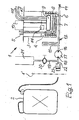
- FIG. 1 an embodiment of the temperature control unit 1 is shown on the right of the dotted line 1 '.
- an optional external buffer tank 2 set up which may also be a temperature medium transport container in the form of a canister which can be temperierwormkeits facedd with the temperature.
- the temperature control device constructed on the principle of a bath thermostat comprises a bath tank 3, which receives a thermally active bath 4 of a temperature control medium.
- the terms "saddle container” and “thermally active bath” are used interchangeably in the present text.
- the bath tank is covered by a non-designated bath cover with a vent 5 of the thermally active bath and provided with an inlet / outlet 6 in the non-designated bottom.
- a temperature-controlled electric heater 7 and an evaporator 8 are also arranged in the bath tank 3.
- Other means of temperature control which belong to conventional bath thermostats, such as a temperature sensor, are not shown.
- a pump 9 which is connected via a flow 10 and a return 10 'with an application, not shown, for example, a reactor or a heat exchanger.
- FIG. 1 a level sensor 11 can be seen, which extends into the region of the thermally active heat transfer fluid and with an electrical Control 12 is connected, which is shown as a block.
- the electrical control includes a software algorithm that can be implemented by hardware.
- the inlet / outlet 6 of the bath tank 3 is connected via a pipe system 13, in which a closable end is a knurled screw 14 for emergency emptying, and a cooling section 15 with a Temperier basicallykeitsan gleich 16 of a reversible metering pump 17 in connection, thus in one of two opposite directions can be switched by a connection, not shown, to the controller 12.
- the internal buffer tank 21 is disposed above the thermally active bath 4 in the bath tank 3 due to its distance from the thermally active bath 4 from being thermally insulated from it.
- this thermal insulation is supported by a solid heat insulation, not shown, around the bath tank 3.
- a Temperier basicallykeitstransport notioner 2 which can serve as an external buffer tank with a larger buffer volume than that of the internal buffer tank 21 only.
- an unspecified further solenoid valve which is actuated by the software algorithm of the controller 12, may be placed in the fluid line 22.
- the shut-off valve 20 in a version as a solenoid valve in the Temperier crampkeitsön 19 to the internal buffer tank 21 the loading of the buffer tank 2 and 21 can thereby be automated, depending on the volume of each tempering liquid is to compensate and depending on whether the external buffer tank is excluded.
- the temperature control unit 1 Before startup of the temperature control unit 1 with at its flow 10 and return 10 'connected, not shown in the drawing application object, the temperature control unit 1 can first from a prefilled external buffer tank 2, which is connected to the hydraulic quick coupling 23, or via a corresponding Temperier basicallykeitstransport meanser with the necessary for operation temperature control liquid are applied.
- the temperature control liquid by means of the metering pump 17, controlled by the electronic control 12, sucked via the hydraulic quick coupling 23 and pressed over the cooling section 15 and the pipe system 13 in the inlet / outlet 6 of the bath tank.
- the tempering liquid is heated or cooled in the thermally active bath 4 by a sensor, not shown, and other means of temperature control to the desired temperature and via the pump 9 and the flow 10 the subject of the application from which it flows back via the return 10 'and the pump 9 in the thermally active bath 4.
- the compensating volume of the thermally active tempering liquid resulting from heating of the thermally active bath 4 causes a change in the level of the thermally active bath 4 which is detected by the level sensor 11 and the electrical control 12, which indicates a deviation of the level of one from the electrical control determined set low target level range, controls the metering pump 17 in the sense that excess compensating volume of the thermally active bath liquid is sucked from the thermally active bath 4 via the inlet / drain or vice versa missing compensating volume supplied by the reversed metering pump 17 to the thermally active bath 4 becomes.
- the Temperierwhikeitsan gleich 18 of the metering pump 17 is connected via the quick coupling 23 with the external buffer tank 2 temperierroughkeits faced or otherwise via the open shut-off valve 20 so connected to the internal buffer tank 21.
Landscapes
- Health & Medical Sciences (AREA)
- Clinical Laboratory Science (AREA)
- Chemical & Material Sciences (AREA)
- Chemical Kinetics & Catalysis (AREA)
- Control Of Temperature (AREA)
- Filling Or Discharging Of Gas Storage Vessels (AREA)
Priority Applications (1)
| Application Number | Priority Date | Filing Date | Title |
|---|---|---|---|
| EP14002680.8A EP2979763A1 (fr) | 2014-07-31 | 2014-07-31 | Appareil de thermorégulation présentant un bain à température contrôlée |
Applications Claiming Priority (1)
| Application Number | Priority Date | Filing Date | Title |
|---|---|---|---|
| EP14002680.8A EP2979763A1 (fr) | 2014-07-31 | 2014-07-31 | Appareil de thermorégulation présentant un bain à température contrôlée |
Publications (1)
| Publication Number | Publication Date |
|---|---|
| EP2979763A1 true EP2979763A1 (fr) | 2016-02-03 |
Family
ID=51292777
Family Applications (1)
| Application Number | Title | Priority Date | Filing Date |
|---|---|---|---|
| EP14002680.8A Withdrawn EP2979763A1 (fr) | 2014-07-31 | 2014-07-31 | Appareil de thermorégulation présentant un bain à température contrôlée |
Country Status (1)
| Country | Link |
|---|---|
| EP (1) | EP2979763A1 (fr) |
Cited By (2)
| Publication number | Priority date | Publication date | Assignee | Title |
|---|---|---|---|---|
| CN113467543A (zh) * | 2021-07-07 | 2021-10-01 | 重庆市计量质量检测研究院 | 便携式多单元恒温装置 |
| EP3974061A1 (fr) * | 2020-09-25 | 2022-03-30 | Lauda Dr. R. Wobser GmbH & Co. KG | Dispositif de mise en température avec système de remplissage, son utilisation et procédé de remplissage |
Citations (3)
| Publication number | Priority date | Publication date | Assignee | Title |
|---|---|---|---|---|
| DE20020391U1 (de) * | 2000-12-01 | 2001-02-15 | Julabo Labortechnik GmbH, 77960 Seelbach | Temperiereinrichtung |
| US20110186283A1 (en) * | 2010-02-03 | 2011-08-04 | Preston Industries, Inc. | Constant Temperature Circulator |
| US20130105002A1 (en) * | 2011-10-28 | 2013-05-02 | Thermo Neslab Inc. | Circulating Liquid Bath With Dual Reservoir Level Switch |
-
2014
- 2014-07-31 EP EP14002680.8A patent/EP2979763A1/fr not_active Withdrawn
Patent Citations (3)
| Publication number | Priority date | Publication date | Assignee | Title |
|---|---|---|---|---|
| DE20020391U1 (de) * | 2000-12-01 | 2001-02-15 | Julabo Labortechnik GmbH, 77960 Seelbach | Temperiereinrichtung |
| US20110186283A1 (en) * | 2010-02-03 | 2011-08-04 | Preston Industries, Inc. | Constant Temperature Circulator |
| US20130105002A1 (en) * | 2011-10-28 | 2013-05-02 | Thermo Neslab Inc. | Circulating Liquid Bath With Dual Reservoir Level Switch |
Cited By (2)
| Publication number | Priority date | Publication date | Assignee | Title |
|---|---|---|---|---|
| EP3974061A1 (fr) * | 2020-09-25 | 2022-03-30 | Lauda Dr. R. Wobser GmbH & Co. KG | Dispositif de mise en température avec système de remplissage, son utilisation et procédé de remplissage |
| CN113467543A (zh) * | 2021-07-07 | 2021-10-01 | 重庆市计量质量检测研究院 | 便携式多单元恒温装置 |
Similar Documents
| Publication | Publication Date | Title |
|---|---|---|
| DE102013011212B4 (de) | Vorrichtung zum Kühlen eines Verbrauchers mit einer unterkühlten Flüssigkeit in einem Kühlkreislauf | |
| DE102006045028B4 (de) | Konstanttemperatur-Flüssigkeitszirkuliervorrichtung und Verfahren zur Steuerung der Temperatur in der Vorrichtung | |
| DE1149032B (de) | Vorrichtung zum Umfuellen tiefsiedender verfluessigter Gase aus einem Transportbehaelter niedrigeren Druckes in einen Lagerbehaelter hoeheren Druckes | |
| WO2016206983A2 (fr) | Procédé de réglage d'une unité de conditionnement et dispositif de mesure de consommation comprenant une unité de conditionnement de ce type | |
| DE102012202375A1 (de) | Heizsystem und Verfahren zu dessen Betrieb | |
| AT519035B1 (de) | Solaranlage | |
| DE1601175B2 (de) | Waermeuebertragungssystem zwischen einem waermespeicher und einem kondensations-waermetauscher | |
| EP2979763A1 (fr) | Appareil de thermorégulation présentant un bain à température contrôlée | |
| DE202013104746U1 (de) | Tankcontainer | |
| DE2943526A1 (de) | Vorrichtung zum anwaermen der druckfluessigkeit fuer die arbeitshydraulik eines kraftfahrzeugs | |
| EP4066700B1 (fr) | Procédé et dispositif de production de mousse de lait et/ou de lait mis en température | |
| EP3339750B1 (fr) | Système d'alimentation en fluide et de circulation de fluide | |
| DE102014212833A1 (de) | Verfahren und Vorrichtung zur Kühlung einer Batterie | |
| WO2017148604A1 (fr) | Procédé pour refroidir un premier contenant sous pression cryogène | |
| DE2245035A1 (de) | Vorrichtung mit einem waermeerzeugenden teil, beispielsweise kompressor fuer ein kuehlsystem | |
| DE102015117848A1 (de) | Fluidsystem und Verfahren zum Steuern eines Fluidsystems | |
| DE1299393B (de) | Warmwassererzeuger, insbesondere Heizwassererzeuger | |
| WO2018082815A2 (fr) | Dispositif de stockage d'énergie thermique | |
| DE19952349C2 (de) | Laborthermostat | |
| EP3076111A1 (fr) | Systeme fluidique et procede de commande d'un systeme fluidique | |
| EP4565815A1 (fr) | Procédé de fonctionnement et/ou de remplissage d'un système d'alimentation en gaz sous pression et dispositif électronique | |
| DE19936523B4 (de) | Kälteanlage | |
| DE2948207A1 (de) | Vorrichtung und verfahren zum erwaermen von wasser durch sonnenenergie | |
| DE102006031860A1 (de) | Speicherbehälter für tiefkaltes Flüssiggas mit einer Entnahmevorrichtung | |
| EP4614100A1 (fr) | Accumulateur thermique à deux zones pour systèmes de chauffage urbain ayant des fluctuations réduites de pression différentielle au niveau du toit intermédiaire |
Legal Events
| Date | Code | Title | Description |
|---|---|---|---|
| PUAI | Public reference made under article 153(3) epc to a published international application that has entered the european phase |
Free format text: ORIGINAL CODE: 0009012 |
|
| AK | Designated contracting states |
Kind code of ref document: A1 Designated state(s): AL AT BE BG CH CY CZ DE DK EE ES FI FR GB GR HR HU IE IS IT LI LT LU LV MC MK MT NL NO PL PT RO RS SE SI SK SM TR |
|
| AX | Request for extension of the european patent |
Extension state: BA ME |
|
| 17P | Request for examination filed |
Effective date: 20160803 |
|
| RBV | Designated contracting states (corrected) |
Designated state(s): AL AT BE BG CH CY CZ DE DK EE ES FI FR GB GR HR HU IE IS IT LI LT LU LV MC MK MT NL NO PL PT RO RS SE SI SK SM TR |
|
| GRAP | Despatch of communication of intention to grant a patent |
Free format text: ORIGINAL CODE: EPIDOSNIGR1 |
|
| RIC1 | Information provided on ipc code assigned before grant |
Ipc: B01L 7/00 20060101AFI20170929BHEP |
|
| INTG | Intention to grant announced |
Effective date: 20171018 |
|
| STAA | Information on the status of an ep patent application or granted ep patent |
Free format text: STATUS: THE APPLICATION IS DEEMED TO BE WITHDRAWN |
|
| 18D | Application deemed to be withdrawn |
Effective date: 20180301 |