EP3974061A1 - Dispositif de mise en température avec système de remplissage, son utilisation et procédé de remplissage - Google Patents
Dispositif de mise en température avec système de remplissage, son utilisation et procédé de remplissage Download PDFInfo
- Publication number
- EP3974061A1 EP3974061A1 EP21197969.5A EP21197969A EP3974061A1 EP 3974061 A1 EP3974061 A1 EP 3974061A1 EP 21197969 A EP21197969 A EP 21197969A EP 3974061 A1 EP3974061 A1 EP 3974061A1
- Authority
- EP
- European Patent Office
- Prior art keywords
- filling
- temperature control
- valve
- gas
- expansion tank
- Prior art date
- Legal status (The legal status is an assumption and is not a legal conclusion. Google has not performed a legal analysis and makes no representation as to the accuracy of the status listed.)
- Granted
Links
Images
Classifications
-
- F—MECHANICAL ENGINEERING; LIGHTING; HEATING; WEAPONS; BLASTING
- F24—HEATING; RANGES; VENTILATING
- F24D—DOMESTIC- OR SPACE-HEATING SYSTEMS, e.g. CENTRAL HEATING SYSTEMS; DOMESTIC HOT-WATER SUPPLY SYSTEMS; ELEMENTS OR COMPONENTS THEREFOR
- F24D3/00—Hot-water central heating systems
- F24D3/10—Feed-line arrangements, e.g. providing for heat-accumulator tanks, expansion tanks ; Hydraulic components of a central heating system
- F24D3/1083—Filling valves or arrangements for filling
-
- F—MECHANICAL ENGINEERING; LIGHTING; HEATING; WEAPONS; BLASTING
- F24—HEATING; RANGES; VENTILATING
- F24D—DOMESTIC- OR SPACE-HEATING SYSTEMS, e.g. CENTRAL HEATING SYSTEMS; DOMESTIC HOT-WATER SUPPLY SYSTEMS; ELEMENTS OR COMPONENTS THEREFOR
- F24D3/00—Hot-water central heating systems
- F24D3/10—Feed-line arrangements, e.g. providing for heat-accumulator tanks, expansion tanks ; Hydraulic components of a central heating system
- F24D3/1008—Feed-line arrangements, e.g. providing for heat-accumulator tanks, expansion tanks ; Hydraulic components of a central heating system expansion tanks
- F24D3/1016—Tanks having a bladder
-
- F—MECHANICAL ENGINEERING; LIGHTING; HEATING; WEAPONS; BLASTING
- F24—HEATING; RANGES; VENTILATING
- F24H—FLUID HEATERS, e.g. WATER OR AIR HEATERS, HAVING HEAT-GENERATING MEANS, e.g. HEAT PUMPS, IN GENERAL
- F24H1/00—Water heaters, e.g. boilers, continuous-flow heaters or water-storage heaters
- F24H1/18—Water-storage heaters
- F24H1/188—Water-storage heaters with means for compensating water expansion
Definitions
- the invention relates to a temperature control device for temperature control of an external process and a method for filling a line system of a temperature control device.
- Temperature control devices for temperature control of external processes are known from the prior art.
- process thermostats are used in which a temperature-controlled heat transfer fluid is pumped to an external application in a closed circuit.
- a temperature control medium tank or an expansion tank is often provided in the temperature control device, in particular for absorbing a change in volume of the liquid as a function of the operating temperature.
- temperature control devices and in particular the expansion tank of the temperature control device, are filled from above, for example by means of a filling funnel.
- a canister filled with a temperature control medium is usually lifted onto the device to enable filling.
- temperature control devices can have a height of, for example, 1.5 m, 2 m or even more.
- a ladder or crane is therefore often required to lift the canister onto the device.
- the filling of the temperature control device is therefore expensive, especially in the case of tall devices.
- filling from above is very slow and the level has to be monitored constantly.
- Another option for filling temperature control units is to provide a liquid pump for sucking in the temperature control medium.
- a liquid pump for sucking in the temperature control medium.
- the object of the invention is to provide a temperature control device that is improved compared to the prior art for temperature control of an external process and an improved method for filling a line system of a temperature control device.
- the object is achieved, for example, by a temperature control device for temperature control of an external process according to claim 1 or by a method for filling a line system of a temperature control device according to claim 11. Further developments of the method or the device are specified in the dependent claims.
- One aspect relates to a temperature control device for temperature control of an external process with a line system comprising a filling valve for connecting a filling container and an equalizing container.
- the temperature control unit also has a gas connection arranged on the expansion tank for the optional admission of pressurized gas to the expansion tank during normal operation, as well as a filling system for sucking a liquid temperature control medium into the line system via the filling valve, comprising a vacuum device fluidly connected to the gas connection for generating a vacuum Negative pressure in the line system during a filling operation.
- the line system includes a heat exchanger for temperature control of the liquid temperature control medium that is in normal operation in the line system.
- the temperature control device can correspond to one of the following devices: process thermostat, water chiller and temperature control station.
- the temperature control device is preferably a process thermostat.
- Further embodiments include a line system with heating and/or cooling for temperature control of the temperature control medium.
- the temperature control device is set up to be connected to an external apparatus in order to form an external temperature control circuit and thus to control the temperature of the external process.
- the temperature control circuit is formed by the line system and the external equipment.
- the line system can Have flow port and a return port for connecting to the external apparatus.
- the line system can also have a heater for heating the temperature control medium, a heat exchanger and/or a liquid pump for conveying the temperature control medium in the temperature control circuit.
- the temperature control circuit is operated at high temperatures, at which the temperature control medium can have a high vapor pressure.
- the temperature control unit, and in particular the line system and the expansion tank, are typically set up to form a high-pressure temperature control circuit.
- the line system, and in particular the expansion tank is designed to be pressure-resistant.
- the temperature control circuit can be pressurized with a pressure of up to 4.5 bar above atmospheric pressure.
- the expansion tank is preferably arranged above the other components of the line system, such as the heater, the liquid pump, the heat exchanger and a supply line and a return line of the line system.
- the expansion tank is a reservoir for providing temperature control medium to the line system or the temperature control circuit and can be provided to compensate for a change in volume of the temperature control medium in the temperature control circuit in the event of a temperature change.
- the expansion tank is typically connected to the supply line and/or the return line, and is therefore also fluidly connected to the temperature control circuit.
- the temperature control device can be set up to be acted upon during normal operation, in particular in the case of high-temperature applications, with gas which is under overpressure.
- the pressurized gas can be compressed air or nitrogen, for example.
- a gas connection is provided on the equalizing tank for charging with gas that is under overpressure.
- the gas connection is typically arranged on an upper side of the expansion tank, in particular in an upper wall section of the expansion tank.
- the temperature control device has a filling system that is set up to fill the expansion tank and thus the temperature control circuit with the temperature control medium to fill up.
- the filling system is fluidly connected to the gas connection of the expansion tank.
- the filling system has a vacuum device which is set up to generate a negative pressure in the expansion tank.
- the filling valve and/or a filling connection of the line system for connecting the filling container can be arranged on an underside or a side wall of the temperature control device.
- the filling valve and/or the filling connection is/are typically arranged on a lower section of the side wall of the temperature control device.
- lifting the filling container onto the temperature control device during a filling operation can be dispensed with.
- no crane or ladder is required to fill up the temperature control circuit and the surge tank.
- the filling container can be arranged laterally next to or at a distance from the temperature control device.
- the filling operation can be carried out significantly faster than in the case of temperature control devices known in the prior art.
- the temperature control medium can easily spill during the filling operation.
- spillage is significantly less likely since there is only one connection of the filling container.
- the filling operation disclosed herein is thus "cleaner".
- the amount of air or gas in the line system, in particular in the temperature control circuit and/or the supply and return line, is significantly reduced by filling the expansion tank using negative pressure, so that subsequent venting or degassing during commissioning is almost completely eliminated. This results in additional time savings and reduced effort.
- the filling system has a suction line which establishes a fluid connection between the vacuum device and the gas connection of the expansion tank.
- the vacuum device may be one selected from a vacuum ejector, a vacuum pump, an electric vacuum generator, or a vacuum blower.
- the vacuum device is preferably a vacuum ejector.
- the vacuum ejector is set up to build up a negative pressure in the intake line and at the gas connection of the expansion tank when gas under overpressure is supplied to the vacuum ejector.
- the vacuum device, and in particular the vacuum ejector is set up to generate a negative pressure (relative to the ambient pressure) of at least 0.1 bar, preferably at least 0.2 bar, and even more preferably at least 0.3 bar in the expansion tank.
- the filling system has a gas connection line for connection to a gas source.
- the gas source can be, for example, a compressed air source or a nitrogen source with an overpressure, preferably of at least 3 bar, more preferably at least 4.5 bar.
- the gas connection line can create a fluid connection between the vacuum device, in particular the vacuum ejector, and the gas source.
- the filling system has a gas outlet line for discharging the gas that is under overpressure and gas sucked in from the expansion tank.
- the gas outlet line is fluidly connected to the vacuum device, in particular the vacuum ejector.
- the vacuum ejector has a jet nozzle arranged between the gas connection line and the gas outlet line.
- a cross section of the jet nozzle narrows, in particular continuously, in the direction of flow.
- the vacuum ejector can have a chamber downstream of the jet nozzle, with a cross section of the chamber widening in the direction of flow.
- the chamber can be connected to the suction line via a suction port.
- the vacuum ejector can also be a multi-stage vacuum ejector.
- the vacuum ejector requires no additional electronic components, is inexpensive and requires little maintenance. Furthermore, in the event that the gas source is used during normal operation to apply the pressurized gas to the expansion tank, the same gas source can also be used for the filling operation. Thus, only a few additional components are required for temperature control devices in which gas is applied during normal operation.
- the temperature control device can have an additional gas line, which fluidly connects the gas source to the gas connection of the expansion tank for charging the expansion tank with the pressurized gas during normal operation.
- the filling system contains a first valve arranged in the gas connection line for controlling a gas supply. Controlling the first valve makes it possible to set a gas flow through the vacuum device, in particular the vacuum ejector, and thus a negative pressure in the intake line. In this way, the suction of the tempering medium can be initiated and a suction speed can be set.
- the first valve is preferably arranged between the gas source and the vacuum ejector.
- the filling system can contain a second valve arranged in the intake line.
- the suction of liquid tempering medium from the expansion tank can be controlled by the second valve.
- the second valve makes it possible to initiate the intake of the tempering medium and to set an intake speed.
- the second valve is preferably arranged between the vacuum ejector and the gas connection of the expansion tank.
- the first valve and/or the second valve can be a solenoid valve.
- the line system also has a filling line with the filling valve arranged therein and/or the filling connection arranged therein.
- the filling line can be connected to the flow line and/or the return line of the line system.
- the line system can have a check valve arranged in the filling line to prevent the tempering medium from flowing back to the filling container exhibit.
- the temperature control device can be set up to open the filling valve completely and/or to set a constant opening angle of the filling valve.
- the temperature control device has a control unit.
- the control unit is set up to at least partially open the first valve and/or the second valve to fill the expansion tank.
- the control unit can also be set up to open and close the filling valve, and in particular to open and close all valves of the temperature control device.
- the control unit can also be set up to control a gas supply through the gas source, for example the control unit can be configured to control an opening valve and/or a pressure reducer of the gas source.
- control unit can be set up to control some or even all of the components of the temperature control device.
- control unit can be configured to control the pump, the cooling and/or the heating.
- the temperature control device has a sensor for detecting a filling level of the expansion tank.
- the control unit can also be set up to close the first valve and/or the second valve when a target filling level of the equalizing tank is reached.
- the setpoint filling level is a filling level that can be freely selected or predefined by the user, in particular for each filling operation, within the limits of a minimum permissible filling level and a maximum permissible filling level.
- the control unit can be set up to close the filling valve after closing the first valve and/or the second valve.
- control unit is configured to automatically fill the expansion tank. It is provided that the components, such as the filling container, are connected by a user (specialist).
- the filling operation itself in particular the opening of the valves, the generation of the negative pressure in the expansion tank, the filling of the expansion tank and the closing of the valves when the Target fill level, however, is carried out automatically by the control unit. All that is required for this is an initiation of the automatic filling, for example by means of a software program or by means of manual input on an operating unit, by the user.
- the temperature control device allows the expansion tank to be filled automatically without the involvement of a user and without a user having to regularly monitor or check the filling operation and the fill level.
- the filling system and/or the control unit can be used to achieve significantly faster filling than in the case of a filling process carried out manually by specialist personnel.
- the automatic filling operation also enables better controlled filling of the expansion tank.
- the temperature control devices disclosed herein Compared to temperature control devices based on the provision of a liquid pump for sucking the temperature control medium into the expansion tank, the temperature control devices disclosed herein require significantly lower costs. Furthermore, cleaning is no longer necessary or cleaning is much more user-friendly. In addition, the temperature control devices disclosed herein enable safe operation. The pipe system cannot be overfilled and/or poured over, as the filling is controlled and ends when the target level is reached.
- the liquid temperature control medium contains water and/or glycol.
- a water-glycol mixture can be used at temperatures well above 100°C.
- the liquid temperature control medium can also preferably contain one selected from the group consisting of silicone oil, fluorinated liquids and thermal oil.
- the filling system is detachably connected to the temperature control device.
- the filling system is located within the housing, for example at or near a top (lid) or upper portion of the side wall of the housing.
- the gas connection line and/or the gas outlet line can be integrated, for example, in the housing of the temperature control device.
- the vacuum device is preferably a vacuum ejector. Operating the vacuum device may include or consist of supplying pressurized gas to the vacuum device. The liquid temperature control medium is sucked in by the negative pressure generated at the gas connection.
- the method is preferably carried out with a vacuum device, and in particular the filling system, according to one of the embodiments disclosed herein.
- the first valve is arranged in a gas connection line that is fluidly connected to the vacuum device.
- the second valve is preferably included in a suction line located between the vacuum device and the gas port.
- Step ii) can also include an at least partial opening of a filling valve.
- the filling valve is preferably arranged between the line system and a filling container filled with liquid temperature control medium.
- the method may further include the step: iii) Interrupting the intake of the liquid temperature control medium when a target filling level of the expansion tank is reached.
- Step iii) is preferably carried out after steps i), and ii).
- the suction is preferably interrupted by closing the first valve to control a gas supply to the vacuum device and/or by closing the second valve to control the suction of the temperature control medium.
- Step iii) can also include closing the filling valve.
- Steps iv) and/or v) occur before steps i), ii), and iii).
- Step iv) may further include connecting the gas source to the gas service line.
- the temperature control device includes a control unit, in particular according to one of the embodiments disclosed herein.
- the control unit is set up to control a method for filling a line system of a temperature control device according to one of the embodiments disclosed herein.
- the control unit is set up to at least partially open the first valve and/or the second valve to fill the expansion tank.
- the control unit can also be set up to open and close the filling valve, and in particular to open and close all valves of the temperature control device.
- the control unit can also be set up to control a gas supply through the gas source, for example the control unit can be configured to control an opening valve and/or a pressure reducer of the gas source.
- the control unit can be set up to control some or all of the components of the temperature control device.
- a further aspect relates to the use of a filling system with a vacuum device for filling an expansion tank of a temperature control device, in particular having the filling system according to one of the embodiments disclosed herein and/or the temperature control device according to one of the embodiments disclosed herein.
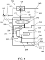
- a temperature control device 200 for temperature control of an external process is shown schematically.
- the temperature control device 200 has a line system 230 .
- the line system 230 contains a heat exchanger 231 for temperature control of a liquid temperature control medium that is in normal operation in the line system 230 .
- the refrigeration system present on a secondary side of the heat exchanger 231 in typical embodiments is not shown for the sake of clarity.
- the line system 230 also contains a pump 220 and a heater 232.
- the line system 230 contains a return connection 233 and a lead port 234 for connection to external equipment.
- An external apparatus can also mean an external line system.
- the section of the line system between the return connection 233 and the pump 220 can also be referred to as a return line.
- the section of the line system between the pump 220 and the flow connection 232 can also be referred to as the flow line.
- a temperature control circuit is formed by the external apparatus; the advance port 234 and the advance line; the return port 233 and the return line; and through the pump 220, the heater 232 and the heat exchanger 231.
- the line system 230 has a compensating tank 210 .
- the expansion tank 210 is in fluid communication with the temperature control circuit and in particular with the return line.
- the expansion tank 210 is filled with the liquid temperature control medium and is used to provide temperature control medium to the temperature control circuit, for example to accommodate a change in volume of the temperature control medium from the temperature control circuit in the event of a temperature change.
- the surge tank is typically located at an upper portion of the temperature control device or directly below the top of the temperature control device.
- the expansion tank contains a gas connection 211.
- the gas connection 211 can be arranged on an upper side of the expansion tank 210, in particular in an upper wall section of the expansion tank.
- the gas connection 211 can be connected to a gas source 150 or can be connected to charge the expansion tank 210 with gas under overpressure during normal operation.
- the line system 230 can have an outlet valve 241 for emptying the expansion tank 210 .
- the outlet valve 241 is in fluid communication with the equalizing tank 210 via a connecting line.
- the exhaust valve 241 is typically at a lower portion of the Temperature control unit arranged to facilitate the discharge of the tempering medium from the expansion tank 210.
- the line system 230 can have an outlet valve 242 for emptying the line system 230 .
- the outlet valve 242 is in fluid communication with the temperature control circuit, for example with the feed line, via a connecting line.
- the outlet valve 242 is typically arranged on a lower section of the temperature control device in order to allow the temperature control medium to be completely drained from the line system 230 .
- the line system has a filling valve 244 .
- the filling valve 244 can be connected or is connected to a filling container 160.
- the filling container 160 contains liquid tempering medium with which the equalizing container 210 can be filled.
- the filling valve 244 is typically arranged on a lower or middle section of the temperature control device 200 .
- a particular arrangement of the valves 241, 242, 243 is shown schematically in Figure 1, but this may be altered as required.
- the outlet valves 241, 242 are optional.
- the temperature control device can only have the filling valve 244 and none of the outlet valves 241, 242. Both the filling and the outlet of the temperature control medium can take place via the filling valve 244.
- the line system 230 can also have a filling line 235 .
- the filling line 235 establishes a fluid connection between the filling valve 244 and the temperature control circuit, for example the flow line.
- the fill line 235 may include the outlet valve 242 for emptying the line system 230 (as in FIG figure 1 shown).
- the temperature control device 200 has a filling system 100 .
- the filling system 100 is located outside the housing (corresponding to the rectangular box) of the temperature control device 200 . In many embodiments, however, the filling system 100 is located within the housing of the temperature control device 200.
- the filling system 100 has a vacuum device 110 .
- the vacuum device 110 shown corresponds to a vacuum ejector.
- the vacuum ejector 110 has three ports: a gas inlet port, a gas outlet port, and a suction port.
- the vacuum ejector 110 can be connected to a gas connection line 111 of the filling system 100 via the gas inlet connection.
- a first valve 120 for controlling a gas supply can be contained in the gas connection line 111 .
- the gas connection line 111 can be connectable or connected to the gas source 150.
- the gas source 150 is used to provide gas that is under overpressure.
- the vacuum ejector 110 can be connected to a gas outlet line 140 of the filling system 100 via the gas outlet connection.
- the gas outlet line 140 is used to discharge the gas that is under overpressure and gas sucked in from the expansion tank 210 .
- the temperature control device 200 can have an application line 201 which connects the gas source 150 or the gas connection line 111 of the filling system 100 directly to the gas connection 211 .
- the admission line 201 can also be connected to the gas outlet line 140 .
- the admission line 201 can have a third valve 202 for controlling a gas supply to the gas connection line 111 and/or a fourth valve 203 for controlling a gas discharge into the gas outlet line 140 .
- the vacuum ejector 110 can be connected to a suction line 112 of the filling system 100 via the suction connection.
- a second valve 130 for controlling the intake of liquid tempering medium can be contained in the intake line 112 .
- the intake line 112 is preferably connected to the gas connection 211 of the expansion tank 210 .
Landscapes
- Engineering & Computer Science (AREA)
- Physics & Mathematics (AREA)
- Thermal Sciences (AREA)
- Chemical & Material Sciences (AREA)
- Combustion & Propulsion (AREA)
- Mechanical Engineering (AREA)
- General Engineering & Computer Science (AREA)
- Filling Or Discharging Of Gas Storage Vessels (AREA)
Applications Claiming Priority (1)
| Application Number | Priority Date | Filing Date | Title |
|---|---|---|---|
| DE102020125113.0A DE102020125113A1 (de) | 2020-09-25 | 2020-09-25 | Temperiergerät |
Publications (2)
| Publication Number | Publication Date |
|---|---|
| EP3974061A1 true EP3974061A1 (fr) | 2022-03-30 |
| EP3974061B1 EP3974061B1 (fr) | 2025-06-11 |
Family
ID=77864499
Family Applications (1)
| Application Number | Title | Priority Date | Filing Date |
|---|---|---|---|
| EP21197969.5A Active EP3974061B1 (fr) | 2020-09-25 | 2021-09-21 | Dispositif de mise en température avec systeme de remplissage, son utilisation et procede de remplissage |
Country Status (2)
| Country | Link |
|---|---|
| EP (1) | EP3974061B1 (fr) |
| DE (1) | DE102020125113A1 (fr) |
Citations (4)
| Publication number | Priority date | Publication date | Assignee | Title |
|---|---|---|---|---|
| DE20020391U1 (de) * | 2000-12-01 | 2001-02-15 | Julabo Labortechnik GmbH, 77960 Seelbach | Temperiereinrichtung |
| EP2476963A2 (fr) * | 2011-01-17 | 2012-07-18 | Judo Wasseraufbereitung GmbH | Procédé de remplissage et de recharge d'eau dans un circuit d'eau |
| EP2979763A1 (fr) * | 2014-07-31 | 2016-02-03 | Lauda Dr. R. Wobser GmbH & Co. KG | Appareil de thermorégulation présentant un bain à température contrôlée |
| DE102015007400A1 (de) * | 2015-06-08 | 2016-12-08 | Monika Müller | Hauswassernetzexterne Heizungswasser-Nachfüllvorrichtung sowie Heizungsanlage und Verfahren zum Nachfüllen von Heizungswasser |
Family Cites Families (3)
| Publication number | Priority date | Publication date | Assignee | Title |
|---|---|---|---|---|
| DE10033280A1 (de) | 2000-07-07 | 2002-01-17 | Andre Laukner | Vorrichtung zur Aufnahme der Wasserausdehnung |
| DE202010014207U1 (de) | 2010-04-24 | 2011-09-07 | Robert Bosch Gmbh | Wärmespeicherbehälter |
| DE102013214156A1 (de) | 2013-07-18 | 2015-01-22 | BSH Bosch und Siemens Hausgeräte GmbH | Warmwasserspeicher |
-
2020
- 2020-09-25 DE DE102020125113.0A patent/DE102020125113A1/de active Pending
-
2021
- 2021-09-21 EP EP21197969.5A patent/EP3974061B1/fr active Active
Patent Citations (4)
| Publication number | Priority date | Publication date | Assignee | Title |
|---|---|---|---|---|
| DE20020391U1 (de) * | 2000-12-01 | 2001-02-15 | Julabo Labortechnik GmbH, 77960 Seelbach | Temperiereinrichtung |
| EP2476963A2 (fr) * | 2011-01-17 | 2012-07-18 | Judo Wasseraufbereitung GmbH | Procédé de remplissage et de recharge d'eau dans un circuit d'eau |
| EP2979763A1 (fr) * | 2014-07-31 | 2016-02-03 | Lauda Dr. R. Wobser GmbH & Co. KG | Appareil de thermorégulation présentant un bain à température contrôlée |
| DE102015007400A1 (de) * | 2015-06-08 | 2016-12-08 | Monika Müller | Hauswassernetzexterne Heizungswasser-Nachfüllvorrichtung sowie Heizungsanlage und Verfahren zum Nachfüllen von Heizungswasser |
Also Published As
| Publication number | Publication date |
|---|---|
| EP3974061B1 (fr) | 2025-06-11 |
| DE102020125113A1 (de) | 2022-03-31 |
Similar Documents
| Publication | Publication Date | Title |
|---|---|---|
| EP0313599B1 (fr) | Dispositif de transfert d'expansion dans des circuits de liquide, notamment d'installations de chauffage ou de refrigeration | |
| EP2361659B1 (fr) | Procédé pour distiller un matériau de départ et installation pour mettre un tel procédé en oeuvre | |
| EP0292814B1 (fr) | Dispositif de régulation, en pression et en volume, d'un liquide circulant en circuit clos | |
| EP3974061B1 (fr) | Dispositif de mise en température avec systeme de remplissage, son utilisation et procede de remplissage | |
| EP2071225B1 (fr) | Procédé de remplissage de réservoir d'hydrure métallique d'un sous-marin avec de l'hydrogène | |
| DE102020132580A1 (de) | Austreibung entzündlicher Gase aus einem Heiz/Solekreislauf | |
| DE102020120505A1 (de) | Ausgleichsbehälteranordnung eines Kühlkreislaufs und Verfahren zum Betreiben einer Ausgleichsbehälteranordnung eines Kühlkreislaufs | |
| DE102004047119B4 (de) | Flüssigkeitszirkuliervorrichtung | |
| EP0580881B1 (fr) | Dispositif pour dégazer des liquides dans des systèmes à circuit de liquides | |
| DE102018211038B4 (de) | Leckageregelungsvorrichtung, elektrische Maschine mit einer Leckageregelungsvorrichtung und Verfahren zum Betreiben einer Leckageregelungsvorrichtung | |
| CH635698A5 (de) | Verfahren zur kuehlung eines brennelement-transportbehaelters. | |
| DE29617756U1 (de) | Vorrichtung für die Bereitung von Brauchwarmwasser | |
| DE102017117704A1 (de) | Vorrichtung und Verfahren zum Druckausgleich von Heizungsanlagen | |
| EP2129975B1 (fr) | Centrale thermique | |
| DE202017106556U1 (de) | Tieftemperatur-Prüfstand | |
| EP3050732A1 (fr) | Récipient collecteur, en particulier pour un environnement à risque d'incendie ou d'explosion | |
| DE2940828C2 (de) | Vorrichtung zum Verhindern von Dampfblasenbildung in einem geschlossenen Leitungssystem | |
| DE102014113671A1 (de) | Vorrichtung mit einem selbststeuernden Druckbehälter zur hydraulischen Entkopplung bei einem Wasserversorgungs-Direktanschluss | |
| DE102013106329B4 (de) | Verfahren und Anordnung zum Evakuieren eines Rohrleitungssystems | |
| DE4407363C2 (de) | Fernwärmesystem und Verfahren zur Rückführung von Dampfleitungsentwässerungskondensat | |
| DE69527771T2 (de) | Verfahren und Vorrichtung zum Wechseln des Kühlmittels eines Motors | |
| DE3129141A1 (de) | Verfahren zur kuehlung eines brennelement-transportbehaelters | |
| DE202024101953U1 (de) | Rauchsäulenvorrichtung für Wasserpfeife | |
| DE2850142A1 (de) | Verfahren und vorrichtung zum betrieb einer wasserstrahlpumpe | |
| AT2554U1 (de) | Verfahren und vorrichtung zur entgasung von heizungswasser in einer heizungsanlage |
Legal Events
| Date | Code | Title | Description |
|---|---|---|---|
| PUAI | Public reference made under article 153(3) epc to a published international application that has entered the european phase |
Free format text: ORIGINAL CODE: 0009012 |
|
| STAA | Information on the status of an ep patent application or granted ep patent |
Free format text: STATUS: THE APPLICATION HAS BEEN PUBLISHED |
|
| AK | Designated contracting states |
Kind code of ref document: A1 Designated state(s): AL AT BE BG CH CY CZ DE DK EE ES FI FR GB GR HR HU IE IS IT LI LT LU LV MC MK MT NL NO PL PT RO RS SE SI SK SM TR |
|
| STAA | Information on the status of an ep patent application or granted ep patent |
Free format text: STATUS: REQUEST FOR EXAMINATION WAS MADE |
|
| 17P | Request for examination filed |
Effective date: 20220919 |
|
| RBV | Designated contracting states (corrected) |
Designated state(s): AL AT BE BG CH CY CZ DE DK EE ES FI FR GB GR HR HU IE IS IT LI LT LU LV MC MK MT NL NO PL PT RO RS SE SI SK SM TR |
|
| GRAP | Despatch of communication of intention to grant a patent |
Free format text: ORIGINAL CODE: EPIDOSNIGR1 |
|
| STAA | Information on the status of an ep patent application or granted ep patent |
Free format text: STATUS: GRANT OF PATENT IS INTENDED |
|
| INTG | Intention to grant announced |
Effective date: 20250109 |
|
| GRAS | Grant fee paid |
Free format text: ORIGINAL CODE: EPIDOSNIGR3 |
|
| GRAA | (expected) grant |
Free format text: ORIGINAL CODE: 0009210 |
|
| STAA | Information on the status of an ep patent application or granted ep patent |
Free format text: STATUS: THE PATENT HAS BEEN GRANTED |
|
| AK | Designated contracting states |
Kind code of ref document: B1 Designated state(s): AL AT BE BG CH CY CZ DE DK EE ES FI FR GB GR HR HU IE IS IT LI LT LU LV MC MK MT NL NO PL PT RO RS SE SI SK SM TR |
|
| REG | Reference to a national code |
Ref country code: GB Ref legal event code: FG4D Free format text: NOT ENGLISH |
|
| REG | Reference to a national code |
Ref country code: CH Ref legal event code: EP |
|
| REG | Reference to a national code |
Ref country code: IE Ref legal event code: FG4D Free format text: LANGUAGE OF EP DOCUMENT: GERMAN |
|
| REG | Reference to a national code |
Ref country code: DE Ref legal event code: R096 Ref document number: 502021007697 Country of ref document: DE |
|
| REG | Reference to a national code |
Ref country code: CH Ref legal event code: U11 Free format text: ST27 STATUS EVENT CODE: U-0-0-U10-U11 (AS PROVIDED BY THE NATIONAL OFFICE) Effective date: 20251001 |
|
| PG25 | Lapsed in a contracting state [announced via postgrant information from national office to epo] |
Ref country code: ES Free format text: LAPSE BECAUSE OF FAILURE TO SUBMIT A TRANSLATION OF THE DESCRIPTION OR TO PAY THE FEE WITHIN THE PRESCRIBED TIME-LIMIT Effective date: 20250611 Ref country code: FI Free format text: LAPSE BECAUSE OF FAILURE TO SUBMIT A TRANSLATION OF THE DESCRIPTION OR TO PAY THE FEE WITHIN THE PRESCRIBED TIME-LIMIT Effective date: 20250611 |
|
| PGFP | Annual fee paid to national office [announced via postgrant information from national office to epo] |
Ref country code: DE Payment date: 20250923 Year of fee payment: 5 |
|
| REG | Reference to a national code |
Ref country code: LT Ref legal event code: MG9D |
|
| PG25 | Lapsed in a contracting state [announced via postgrant information from national office to epo] |
Ref country code: GR Free format text: LAPSE BECAUSE OF FAILURE TO SUBMIT A TRANSLATION OF THE DESCRIPTION OR TO PAY THE FEE WITHIN THE PRESCRIBED TIME-LIMIT Effective date: 20250912 Ref country code: NO Free format text: LAPSE BECAUSE OF FAILURE TO SUBMIT A TRANSLATION OF THE DESCRIPTION OR TO PAY THE FEE WITHIN THE PRESCRIBED TIME-LIMIT Effective date: 20250911 |
|
| REG | Reference to a national code |
Ref country code: NL Ref legal event code: MP Effective date: 20250611 |
|
| PG25 | Lapsed in a contracting state [announced via postgrant information from national office to epo] |
Ref country code: BG Free format text: LAPSE BECAUSE OF FAILURE TO SUBMIT A TRANSLATION OF THE DESCRIPTION OR TO PAY THE FEE WITHIN THE PRESCRIBED TIME-LIMIT Effective date: 20250611 |
|
| PGFP | Annual fee paid to national office [announced via postgrant information from national office to epo] |
Ref country code: GB Payment date: 20250919 Year of fee payment: 5 |
|
| PG25 | Lapsed in a contracting state [announced via postgrant information from national office to epo] |
Ref country code: HR Free format text: LAPSE BECAUSE OF FAILURE TO SUBMIT A TRANSLATION OF THE DESCRIPTION OR TO PAY THE FEE WITHIN THE PRESCRIBED TIME-LIMIT Effective date: 20250611 |
|
| PGFP | Annual fee paid to national office [announced via postgrant information from national office to epo] |
Ref country code: AT Payment date: 20251020 Year of fee payment: 5 Ref country code: FR Payment date: 20250922 Year of fee payment: 5 |
|
| PG25 | Lapsed in a contracting state [announced via postgrant information from national office to epo] |
Ref country code: RS Free format text: LAPSE BECAUSE OF FAILURE TO SUBMIT A TRANSLATION OF THE DESCRIPTION OR TO PAY THE FEE WITHIN THE PRESCRIBED TIME-LIMIT Effective date: 20250911 |
|
| PG25 | Lapsed in a contracting state [announced via postgrant information from national office to epo] |
Ref country code: LV Free format text: LAPSE BECAUSE OF FAILURE TO SUBMIT A TRANSLATION OF THE DESCRIPTION OR TO PAY THE FEE WITHIN THE PRESCRIBED TIME-LIMIT Effective date: 20250611 |
|
| PG25 | Lapsed in a contracting state [announced via postgrant information from national office to epo] |
Ref country code: NL Free format text: LAPSE BECAUSE OF FAILURE TO SUBMIT A TRANSLATION OF THE DESCRIPTION OR TO PAY THE FEE WITHIN THE PRESCRIBED TIME-LIMIT Effective date: 20250611 |
|
| PG25 | Lapsed in a contracting state [announced via postgrant information from national office to epo] |
Ref country code: PT Free format text: LAPSE BECAUSE OF FAILURE TO SUBMIT A TRANSLATION OF THE DESCRIPTION OR TO PAY THE FEE WITHIN THE PRESCRIBED TIME-LIMIT Effective date: 20251013 |
|
| PG25 | Lapsed in a contracting state [announced via postgrant information from national office to epo] |
Ref country code: IS Free format text: LAPSE BECAUSE OF FAILURE TO SUBMIT A TRANSLATION OF THE DESCRIPTION OR TO PAY THE FEE WITHIN THE PRESCRIBED TIME-LIMIT Effective date: 20251011 |
|
| PG25 | Lapsed in a contracting state [announced via postgrant information from national office to epo] |
Ref country code: SM Free format text: LAPSE BECAUSE OF FAILURE TO SUBMIT A TRANSLATION OF THE DESCRIPTION OR TO PAY THE FEE WITHIN THE PRESCRIBED TIME-LIMIT Effective date: 20250611 |
|
| PGFP | Annual fee paid to national office [announced via postgrant information from national office to epo] |
Ref country code: CH Payment date: 20251001 Year of fee payment: 5 |
|
| PG25 | Lapsed in a contracting state [announced via postgrant information from national office to epo] |
Ref country code: CZ Free format text: LAPSE BECAUSE OF FAILURE TO SUBMIT A TRANSLATION OF THE DESCRIPTION OR TO PAY THE FEE WITHIN THE PRESCRIBED TIME-LIMIT Effective date: 20250611 |
|
| PG25 | Lapsed in a contracting state [announced via postgrant information from national office to epo] |
Ref country code: PL Free format text: LAPSE BECAUSE OF FAILURE TO SUBMIT A TRANSLATION OF THE DESCRIPTION OR TO PAY THE FEE WITHIN THE PRESCRIBED TIME-LIMIT Effective date: 20250611 |
|
| PG25 | Lapsed in a contracting state [announced via postgrant information from national office to epo] |
Ref country code: EE Free format text: LAPSE BECAUSE OF FAILURE TO SUBMIT A TRANSLATION OF THE DESCRIPTION OR TO PAY THE FEE WITHIN THE PRESCRIBED TIME-LIMIT Effective date: 20250611 |
|
| PG25 | Lapsed in a contracting state [announced via postgrant information from national office to epo] |
Ref country code: RO Free format text: LAPSE BECAUSE OF FAILURE TO SUBMIT A TRANSLATION OF THE DESCRIPTION OR TO PAY THE FEE WITHIN THE PRESCRIBED TIME-LIMIT Effective date: 20250611 Ref country code: SK Free format text: LAPSE BECAUSE OF FAILURE TO SUBMIT A TRANSLATION OF THE DESCRIPTION OR TO PAY THE FEE WITHIN THE PRESCRIBED TIME-LIMIT Effective date: 20250611 |
|
| REG | Reference to a national code |
Ref country code: DE Ref legal event code: R097 Ref document number: 502021007697 Country of ref document: DE |
|
| PG25 | Lapsed in a contracting state [announced via postgrant information from national office to epo] |
Ref country code: DK Free format text: LAPSE BECAUSE OF FAILURE TO SUBMIT A TRANSLATION OF THE DESCRIPTION OR TO PAY THE FEE WITHIN THE PRESCRIBED TIME-LIMIT Effective date: 20250611 |
|
| PG25 | Lapsed in a contracting state [announced via postgrant information from national office to epo] |
Ref country code: IT Free format text: LAPSE BECAUSE OF FAILURE TO SUBMIT A TRANSLATION OF THE DESCRIPTION OR TO PAY THE FEE WITHIN THE PRESCRIBED TIME-LIMIT Effective date: 20250611 |
|
| PLBE | No opposition filed within time limit |
Free format text: ORIGINAL CODE: 0009261 |
|
| STAA | Information on the status of an ep patent application or granted ep patent |
Free format text: STATUS: NO OPPOSITION FILED WITHIN TIME LIMIT |
|
| REG | Reference to a national code |
Ref country code: CH Ref legal event code: L10 Free format text: ST27 STATUS EVENT CODE: U-0-0-L10-L00 (AS PROVIDED BY THE NATIONAL OFFICE) Effective date: 20260423 |