EP2979875A1 - Appareil de formation d'image à jet d'encre et procédé de nettoyage pour appareil de formation d'image à jet d'encre - Google Patents
Appareil de formation d'image à jet d'encre et procédé de nettoyage pour appareil de formation d'image à jet d'encre Download PDFInfo
- Publication number
- EP2979875A1 EP2979875A1 EP15179070.6A EP15179070A EP2979875A1 EP 2979875 A1 EP2979875 A1 EP 2979875A1 EP 15179070 A EP15179070 A EP 15179070A EP 2979875 A1 EP2979875 A1 EP 2979875A1
- Authority
- EP
- European Patent Office
- Prior art keywords
- ink
- wipe
- nozzle
- flush
- image forming
- Prior art date
- Legal status (The legal status is an assumption and is not a legal conclusion. Google has not performed a legal analysis and makes no representation as to the accuracy of the status listed.)
- Granted
Links
Images




Classifications
-
- B—PERFORMING OPERATIONS; TRANSPORTING
- B41—PRINTING; LINING MACHINES; TYPEWRITERS; STAMPS
- B41J—TYPEWRITERS; SELECTIVE PRINTING MECHANISMS, i.e. MECHANISMS PRINTING OTHERWISE THAN FROM A FORME; CORRECTION OF TYPOGRAPHICAL ERRORS
- B41J2/00—Typewriters or selective printing mechanisms characterised by the printing or marking process for which they are designed
- B41J2/005—Typewriters or selective printing mechanisms characterised by the printing or marking process for which they are designed characterised by bringing liquid or particles selectively into contact with a printing material
- B41J2/01—Ink jet
- B41J2/135—Nozzles
- B41J2/165—Prevention or detection of nozzle clogging, e.g. cleaning, capping or moistening for nozzles
- B41J2/16517—Cleaning of print head nozzles
- B41J2/16535—Cleaning of print head nozzles using wiping constructions
-
- B—PERFORMING OPERATIONS; TRANSPORTING
- B41—PRINTING; LINING MACHINES; TYPEWRITERS; STAMPS
- B41J—TYPEWRITERS; SELECTIVE PRINTING MECHANISMS, i.e. MECHANISMS PRINTING OTHERWISE THAN FROM A FORME; CORRECTION OF TYPOGRAPHICAL ERRORS
- B41J2/00—Typewriters or selective printing mechanisms characterised by the printing or marking process for which they are designed
- B41J2/005—Typewriters or selective printing mechanisms characterised by the printing or marking process for which they are designed characterised by bringing liquid or particles selectively into contact with a printing material
- B41J2/01—Ink jet
- B41J2/135—Nozzles
- B41J2/165—Prevention or detection of nozzle clogging, e.g. cleaning, capping or moistening for nozzles
- B41J2/16517—Cleaning of print head nozzles
- B41J2/16535—Cleaning of print head nozzles using wiping constructions
- B41J2/16538—Cleaning of print head nozzles using wiping constructions with brushes or wiper blades perpendicular to the nozzle plate
-
- B—PERFORMING OPERATIONS; TRANSPORTING
- B41—PRINTING; LINING MACHINES; TYPEWRITERS; STAMPS
- B41J—TYPEWRITERS; SELECTIVE PRINTING MECHANISMS, i.e. MECHANISMS PRINTING OTHERWISE THAN FROM A FORME; CORRECTION OF TYPOGRAPHICAL ERRORS
- B41J2/00—Typewriters or selective printing mechanisms characterised by the printing or marking process for which they are designed
- B41J2/005—Typewriters or selective printing mechanisms characterised by the printing or marking process for which they are designed characterised by bringing liquid or particles selectively into contact with a printing material
- B41J2/01—Ink jet
- B41J2/135—Nozzles
- B41J2/165—Prevention or detection of nozzle clogging, e.g. cleaning, capping or moistening for nozzles
- B41J2/16517—Cleaning of print head nozzles
- B41J2/16535—Cleaning of print head nozzles using wiping constructions
- B41J2/16544—Constructions for the positioning of wipers
Definitions
- the present invention relates to an inkjet image forming apparatus and to a cleaning method therefor.
- a cleaning operation is done as one of cleaning operations in an inkjet image forming apparatus in order to keep proper ink injections from inkjet heads.
- a purge process in which inks are forcibly injected from ink injection surfaces of inkjet heads
- a wipe process in which dusts attached onto the ink injection surface is wiped out by a wiper blade or the like together with inks remained on the ink injection surface is done
- a flush process in which mixed inks staying in nozzles are forcibly injected out, are done sequentially.
- Patent Document 1 Japanese Patent Application Publication No. 2000-233518 discloses an "ink-jet recoding apparatus" that includes inkjet heads for forming dots on a record medium by injecting ink droplets from nozzles according to print data.
- flush conditions are changed with respect to each of the nozzles in order to do flushing (cleaning) efficiently.
- the flush conditions are changed by changing an amount of ink injected from each of the nozzles.
- a nozzle that injects ink having larger thickening rate is controlled so as to injects a larger amount of ink in order to recover an injection capability sufficiently.
- An object of the present invention is to provide an inkjet image forming apparatus and a cleaning method for the apparatus that can prevent increase of an amount of ink used in a flush process and can prolong a replacement cycle of a mist-absorbing material.
- a first aspect of the present invention provides an inkjet image forming apparatus comprising: a plurality of inkjet heads each of which has two or more nozzle rows from which ink of different colors is injected, each of the nozzle rows including nozzle holes; a wipe unit that includes wipers and carries out a wipe process to wipe away ink remained on a surface on which the nozzle rows are formed by the wipers; and a flush unit that carries out a flush process after the wipe process by injecting ink from nozzle holes into which ink of different color from color of ink that is injected from the nozzle holes flows during the wipe process.
- the flush unit carries out the flush process only for nozzle holes in a predetermined area located on an upstream side in a wipe direction of the wipers.
- the wipers are inclined with respect to a transfer direction of a print sheet, and the flush unit carried out the flush process by flushing only for one of the nozzle rows of each of the inkjet heads, ink being flown into the one of the nozzle rows by the wiper during the wipe process.
- the inkjet heads are aligned along the transfer direction so as to form two rows that are parallel to each other and are perpendicular to the transfer direction, and an inclination of the wiper for one of the two rows and an inclination of the wiper for another of the two rows are different from each other.
- the flush unit carried out the flush process so that an amount of ink injected for flushing in the flush process is gradually made smaller sequentially from a most-upstream nozzle hole in a wipe direction of the wipers.
- a second aspect of the present invention provides a cleaning method for an inkjet image forming apparatus that includes a plurality of inkjet heads each of which has two or more nozzle rows from which ink of different colors is injected, each of the nozzle rows including nozzle holes, the method comprising: carrying out a wipe process to wipe away ink remained on a surface on which the nozzle rows are formed by wipers; and carrying out a flush process after the wipe process by injecting ink from nozzle holes into which ink of different color from color of ink that is injected from the nozzle holes flows during the wipe process.
- an inkjet image forming apparatus 1 includes a sheet transfer unit 2, a head unit 3, a cleaning unit 4, and a controller 5.
- the sheet transfer unit 2 includes a transfer belt 21 disposed so as to face to the head unit 3, a drive roller 22 that drives the transfer belt 21 circularly, and driven rollers 23 to 25 that are driven by the drive roller 22 via the transfer belt 21.
- the transfer belt 21 is wound around the drive roller 22 and the driven rollers 23 to 25, and driven by the drive roller 22 endlessly during printing.
- the transfer belt 21 transfers a sheet (print paper) P fed from a sheet supply tray (not shown in the drawings) disposed on a left side in Fig. 1 to the head unit 3 (i.e. transfers the sheet P forward: rightward in Fig. 1 ).
- the sheet transfer unit 2 can be moved vertically by an elevation motor 42 (see Fig. 2 ) to (1) a print position where the sheet transfer unit 2 executes a transfer process of the sheet P for printing, (2) a waiting position that is located beneath the printing position as shown in Fig. 6 and where the cleaning unit 4 is inserted between the sheet transfer unit 2 and the head unit 3, and (3) a cleaning position that is located above the wait position as shown in Fig. 7 and where the head unit 3 is cleaned by the cleaning unit 4 moved up together with the sheet transfer unit 2 moved up from the wait position.
- the downward movement of the sheet transfer unit 2 to the wait position is made for inserting the cleaning unit 4 between the sheet transfer unit 2 and the head unit 3. It depends on a height of the cleaning unit 4 which is located higher, the print position or the cleaning position.
- the head unit 3 includes inkjet heads 31 and 32 each of which has two nozzle rows for two colors. Namely, each of the inkjet heads 31 and 32 is a 1-head-2-color line-type inkjet head.
- the head unit 3 (the inkjet heads 31 and 32) prints images on a sheet P by injecting ink droplets onto the sheet P transferred by the transfer belt 21.
- the inkjet heads 31 (31a to 31f) and 32 (32a to 32f) are arranged in a staggered manner to form a 2 ⁇ 3 matrix arrangement.
- the inkjet heads 31a to 31c are provided as its first column, and the inkjet heads 31d to 31f are provided as its second column. Each of the inkjet heads 31a to 31f has two nozzle rows for two colors.
- the inkjet heads 32a to 32c are provided as its first column, and the inkjet heads 32d to 32f are provided as its second column. Each of the inkjet heads 32a to 32f has two nozzle rows for two colors.
- the head unit 3 includes the inkjet heads 31a to 31f that accumulate black (K) and cyan (C) inks, and the inkjet heads 32a to 32f that accumulate magenta (M) and yellow (Y) inks.
- K black
- C cyan
- M magenta
- Y yellow
- the inkjet heads 31a to 31f and the inkjet heads 32a to 32f inject different color inks from each other, but they have an identical physical structure to each other.
- An ink chamber for accumulating black (K) ink or cyan (C) ink is formed in each inkjet heads 31a to 31f, and a piezoelectric element is disposed within the ink chamber.
- a drive voltage(s) for injecting ink is applied to the piezoelectric element based on a supplied signal, and thereby black (K) ink droplets are injected from upstream nozzle rows 311 and cyan (C) ink droplets are injected from downstream nozzle rows 312.
- the black (K) and cyan (C) ink droplets are printed with a resolution of 300 dpi. Namely, nozzles in the nozzle rows 311 and 312 are aligned along the primary sweep direction so as to inject ink droplets with a resolution of 300 dpi.
- an upstream nozzle row 321 for injecting magenta (M) ink droplets and a downstream nozzle rows 322 for injecting yellow (Y) ink droplets are aligned parallel to the primary sweep direction and parallel to each other so that the magenta (M) and yellow (Y) ink droplets are printed with a resolution of 300 dpi.
- An ink chamber for accumulating magenta (M) ink or yellow (Y) ink is formed in each inkjet heads 32a to 32f, and a piezoelectric element is disposed within the ink chamber.
- a drive voltage(s) for injecting ink is applied to the piezoelectric element based on a supplied signal, and thereby magenta (M) ink droplets are injected from the upstream nozzle rows 321 and yellow (Y) ink droplets are injected from the downstream nozzle rows 322.
- the magenta (M) and yellow (Y) ink droplets are also printed with a resolution of 300 dpi.
- the cleaning unit 4 cleans an ink injection surface of each of the inkjet heads 31 (31a to 31f) and the inkjet head 32 (32a to 32f). As shown in Fig. 2 , the cleaning unit 4 includes a set motor 41, the elevation motor 42, a purge unit 43, a wipe unit 44, and a flush unit 45.
- the cleaning unit 4 is located at its home position (accommodated position) that is shown by solid lines in Fig. 1 while printing is being done.
- the home position (accommodated position) is located on a lower-right side (in Fig. 1 ) of the sheet transfer unit 2.
- the sheet transfer unit 2 is moved downward to the wait position (see Fig. 5 ) by the elevation motor 42, and then the cleaning unit 4 is moved (set) to a position set above the sheet transfer unit 2 (see Fig. 6 ) by the set motor 41.
- the cleaning unit 4 is moved upward to its cleaning position that is shown by dotted lined in Fig. 1 together with the sheet transfer unit 2 (see Fig. 7 ) by the elevation motor 42.
- the cleaning position is located between the sheet transfer unit 2 and the head unit 3.
- the set motor 41 moves the cleaning unit 4 from the home position (accommodated position) to the cleaning position [and also moves back the cleaning unit 4 from the cleaning unit 4 to the home position (accommodated position)].
- the elevation motor 42 elevates the cleaning unit 4 upward or downward together with the sheet transfer unit 2 [and also elevates only the sheet transfer unit 2 upward and downward].
- the controller 5 controls operations of the inkjet image forming apparatus 1 to form images on a sheet (print sheet) P by controlling operations of the sheet transfer unit 2 and the head unit 3.
- the controller 5 includes a purge unit 43, a wipe unit 44 and a flush unit 45 on order to achieve its function, and carries out an after-described cleaning operation when a cleaning condition is satisfied by sending operation start signals to the purge unit 43, the wipe unit 44 and the flush unit 45.
- the purge unit 43 carries out a purge process in the clearing operation.
- ink in the inkjet heads 31 and 32 is injected from the nozzle rows 311, 312. 321 and 322 of each of the inkjet heads 31 and 32 of the head unit 3.
- the ink injected from the nozzle rows 311, 312. 321 and 322 becomes droplets, and the droplets stay on a nozzle surface as purged ink droplets without dropping off from the nozzle surface.
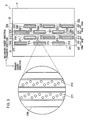
- the wipe unit 44 includes wipers 44a each of which is provided for each column of the inkjet heads 31 and 32 as shown in Fig. 3 . Namely, the wipers 44a are provided for a row of the inkjet heads 31a to 31c, a row of the inkjet heads 31d to 31f, a row of inkjet heads 32a to 32c, and a row of the inkjet heads 32d to 32f.
- the wipers 44a are parallel to the secondary sweep direction (transfer direction). After the purge process by the purge unit 43, the wipe unit 44 carries out a wipe process.
- the wipers 44a are moved in the primary sweep direction by a wiper motor (not shown in the drawings) to wipe out the purged ink droplets staying on the nozzle surface of the nozzle rows 311, 312. 321 and 322 of the inkjet heads 31 and 32.
- the flush unit 45 carries out a flush process.
- ink is injected from the nozzle holes into which ink of different color from its color flows on the inkjet heads 31 and 32.
- black (K) ink is prevented from flowing into the nozzles that inject cyan (C) ink by the flush process
- cyan (C) ink is prevented from flowing into the nozzles that inject black (K) ink by the flush process.
- magenta (M) ink is prevented from flowing into the nozzles that inject yellow (Y) ink by the flush process, and yellow (Y) ink is prevented from flowing into the nozzles that inject magenta (M) ink by the flush process.
- step S101 When a cleaning condition is satisfied (YES in step S101), the controller 5 moves the cleaning unit 4 to the cleaning position (step S103).
- the cleaning condition is satisfied, when the number of print operations has reached to the preset number of time.
- the cleaning condition is satisfied, when a user inputs a cleaning start command.
- the process of the step S103 will be explained more in detail.
- the controller 5 sends control commands to the elevation motor 42 to move the sheet transfer unit 2 downward to the wait position as shown in Fig. 5 , and then sends control commands to the set motor 41 to move the cleaning unit 4 located at the home position (accommodated position) as shown in Fig. 5 to a position between the sheet transfer unit 2 located at the wait position and the head unit 3 as shown in Fig. 6 .
- the controller 5 sends control commands to the elevation motor 42 to move the cleaning unit 4 and the sheet transfer unit 2 upward to the cleaning position as shown in Fig. 7 .
- the purge unit 43 carries out the purge process by injecting ink (black (K), cyan (C), magenta (M) and yellow(Y)) from nozzle rows 311, 312, 321 and 322 of the inkjet heads 31 and 32 of the head unit 3 (step S105).
- the wipe unit 44 carries out the wipe process by moving the wipers 44a in the primary sweep direction perpendicular to the transfer direction.
- the flush unit 45 carries out the flush process by injecting ink (black (K), cyan (C), magenta (M) and yellow(Y)) from nozzle rows 311, 312, 321 and 322 of the inkjet heads 31 and 32 of the head unit 3 so that the ink is injected to generate mist (step S109).
- the flush unit 45 carries out the flush process only for a nozzle group(s) that includes nozzles into which ink of different color may be mixed with its ink in the nozzle rows 311, 312, 321 and 322 of the inkjet heads 31 and 32 of the head unit 3.
- the controller 5 moves the sheet transfer unit 2 downward to the wait position together with the cleaning unit 4 by driving the elevation motor 42 as shown in Fig.6 , and then moves the cleaning unit 4 back to the home position (accommodated position) by driving the set motor 41 as shown in Fig. 5 (step S111). Subsequently, the sheet transfer unit 2 is moved upward by the elevation motor 42 to the print position as shown in Fig. 1 .
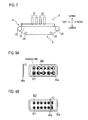
- Fig. 8A and Fig. 8B shows a current cleaning state (adequate state) of the 1-head-2-color inkjet head 32a.
- magenta (M) ink is injected through nozzle holes in the nozzle row 321
- yellow (Y) ink is injected through nozzle holes in the nozzle row 322, in the purge process as shown in Fig. 8A .
- nozzle holes in the nozzle rows 321 and 322 are shown larger than their actual size in Fig. 8A to Fig. 10B conveniently for explanations.
- the nozzle holes are much smaller than purged ink droplets as shown in Fig. 11 , and a single purged ink droplet is formed by gathering of ink injected from plural nozzle holes.
- ink of different color doesn't flow into the nozzle holes even when the wiper 44a and/or on an upstream side of the inkjet head 32a is soiled by ink.
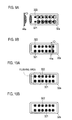
- the remained ink may flows into the nozzle holes located most-upstream that are not covered by purged ink droplets (i.e. no ink is supplied to the nozzle holes located most-upstream in the purge process) and thereby mixture of inks of different colors occurs as shown in Fig. 9B .
- FIG. 10A A flush area in the inkjet image forming apparatus 1 according to the present embodiment is shown in Fig. 10A .
- Fig. 10A and Fig. 10B shows a state where mixture of ink is prevented in the 1-head-2-color inkjet head 32a by flushing.
- the flush unit 45 of the inkjet image forming apparatus 1 according to the present embodiment carries out flushing only for a nozzle group in a predetermined area located on an upstream side in the wipe direction where mixture of ink tends to occur, as shown in Fig. 10A .
- the flush unit 45 carries out flushing at least for a tend-to-occur area of mixture of ink, i.e. a predetermined area from a location of the most-upstream nozzle holes to a position of most-upstream purged ink droplets, in other words, an area from a location of the most-upstream nozzle holes to a positon downstream by a pitch IDp from the location of the most-upstream nozzle holes as shown in Fig. 11 .
- the pitch IDp is a pitch between purged ink droplets (to be) formed by gathering of ink injected from plural nozzle holes.
- the flush unit 45 Since there is a high possibility of mixture of ink at the nozzle group located upstream in the wipe direction as shown in Fig. 9A and Fig. 9B , at least the above-explained flush area is flushed by the flush unit 45 in the present embodiment.
- the nozzle holes in the nozzle rows is aligned straight in Fig. 11 , but they may be aligned obliquely per a predetermined number of them (per three nozzle holes) as in the nozzle rows 311 and 312 shown in Fig. 3 .
- the flush process is carried out only at the nozzle group in the predetermined area that is located on the most-upstream side in the wipe direction and in which mixture of ink tends to occur in the wipe process by the wiper(s) 44a, consumption of ink in the flush process can be prevented from increasing, and a replacement cycle of a mist-absorbing material for absorbing ink mists generated during the flush process can be prolonged.
- the flush may be carried out so that an amount of ink injected for flushing in the flush area in which mixture of ink tends to occur is gradually made smaller sequentially from the most-upstream nozzle hole(s).
- an amount of ink injected from the most-upstream nozzle hole(s) is set to 15 droplets
- an amount of ink injected from the second-upstream nozzle hole(s) is set to 10 droplets
- an amount of ink injected from the third-upstream nozzle hole(s) is 5 droplets. According to this, consumption of ink in the flush process can be reduced more, and a replacement cycle of a mist-absorbing material for absorbing ink mists generated during the flush process can be prolonged further.
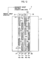
- the wipers 44a are inclined with respect to the secondary sweep direction (transfer direction) in order to reduce an amount of ink injected in the flush process (i.e. consumption of ink in the flush process) further.
- all the wipers 44a are inclined so as to be parallel to each other.
- the wipers 44a are provided for a row of the inkj et heads 31a to 31c, a row of the inkjet heads 31d to31f, a row of inkjet heads 32a to 32c, and a row of the inkjet heads 32d to 32f. Namely, the wipers 44a are inclined with respect to the rows.
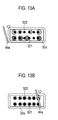
- the wipe process is carried out as shown in Fig. 13A and 13B (explained by taking the inkjet head 32a as an example).
- ink droplets are wiped away to a constant side (rightward in Fig. 12 ) regardless of a state of the purged ink droplets.
- ink droplets are wiped from a side of the nozzle row 311 of black (K) ink to a side of the nozzle row 312 of cyan (C) ink with respect to each of the inkjet heads 31a to 31f, and ink droplets are wiped away from a side of the nozzle row 321 of magenta (M) ink to a side of the nozzle row 322 of yellow (Y) ink with respect to each of the inkjet heads 32a to 32f.
- K black
- M magenta
- Y yellow
- magenta (M) ink purged from the nozzle row 321 may flows into the nozzle row 322 of yellow (Y) ink by the swipe process and thereby mixture of ink may occur on the nozzle row 322.
- the flush unit 45 carries out flushing only for one (322) of the nozzle rows 321 and 322 on which mixture of ink tends to occur due to the inclined wiper 44a.
- mixture of ink tends to occur on the nozzle row 322 of yellow (Y) ink more likely than on the nozzle row 321 of magenta (M) ink, so that flushing is carried out only for the nozzle row 322 and doesn't for the nozzle row 321.
- the inkjet image forming apparatus 1 in the present embodiment since flushing is carried out only for a nozzle row on which mixture of ink tends to occur due to the inclined wiper 44a, consumption of ink in the flush process can be reduced further, and a replacement cycle of the mist-absorbing material can be prolonged further.
- flushing may be carried out only in a predetermined area located on an upstream side in the wipe direction similarly in the above first embodiment.
- flushing is carried out only for a nozzle row on which mixture of ink tends to occur due to the inclined wiper 44a in the predetermined area located on an upstream side in the wipe direction. According to this, consumption of ink in the flush process can be reduced much further, and a replacement cycle of the mist-absorbing material can be prolonged much further.
- the wipers 44a are inclined with respect to the secondary sweep direction (transfer direction) in order to reduce an amount of ink injected in the flush process (i.e. consumption of ink in the flush process) further, similarly to the above-described second embodiment.
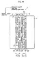
- inclinations of the two wipers 44a in each of the inkjet heads 31 and 32 are different from each other as shown in Fig. 14 .
- flushing is carried out only for one of the nozzle rows. Therefore, ink for the one of the nozzle rows is consumed more than ink for another of the nozzle rows.
- ink consumption is averaged with respect to all colors.
- the wiper 44a for the row of the inkjet heads 31a to 31c and the wiper 44a for the row of the inkjet heads 31d to 31f are inclined in different directions from each other.
- the wiper 44a for the row of the inkjet heads 32a to 32c and the wiper 44a for the row of the inkjet heads 32d to 32f are inclined in different directions from each other.
- the wiper 44a for the row of the inkjet heads 31a to 31c (on an upstream side along the transfer direction) and the wiper 44a for the row of the inkjet heads 31d to 31f (on a downstream side along the transfer direction) are inclined in opposite directions to each other.
- the wiper 44a is inclined so that black (K) ink purged from the nozzle row 311 may flows into the nozzle row 312 of cyan (C) ink by the swipe process.
- the wiper 44a is inclined so that cyan (C) ink purged from the nozzle row 312 may flows into the nozzle row 311 of black (K) ink by the swipe process.
- flushing is carried out only for the nozzle row(s) 312 of cyan (C) ink by the flush process.
- flushing is carried out only for the nozzle row(s) 311 of black (K) ink by the flush process.
- the wiper 44a is inclined so that yellow (Y) ink purged from the nozzle row 322 may flows into the nozzle row 321 of magenta (M) ink by the swipe process.
- the wiper 44a is inclined so that magenta (M) ink purged from the nozzle row 321 may flows into the nozzle row 322 of yellow (Y) ink by the swipe process.
- flushing is carried out only for the nozzle row(s) 321 of magenta (M) ink by the flush process.
- flushing is carried out only for the nozzle row(s) 322 of yellow (Y) ink by the flush process.
- the inkjet image forming apparatus 1 in the present embodiment since flushing is carried out only for a nozzle row on which mixture of ink tends to occur due to the inclined wiper 44a, flushing is not needed for another nozzle row. Therefore, consumption of ink in the flush process can be reduced much further, and a replacement cycle of the mist-absorbing material can be prolonged much further.
- the present invention is not limited to the above-mentioned embodiment and modified examples, and it is possible to embody the present invention by modifying its components in a range that does not depart from the scope thereof. Further, it is possible to form various kinds of inventions by appropriately combining a plurality of components disclosed in the above-mentioned embodiment and modified examples. For example, it may be possible to omit several components from all of the components shown in the above-mentioned embodiment.
Landscapes
- Ink Jet (AREA)
- Particle Formation And Scattering Control In Inkjet Printers (AREA)
Applications Claiming Priority (1)
| Application Number | Priority Date | Filing Date | Title |
|---|---|---|---|
| JP2014156006A JP6378961B2 (ja) | 2014-07-31 | 2014-07-31 | インクジェット画像形成装置およびクリーニング方法 |
Publications (2)
| Publication Number | Publication Date |
|---|---|
| EP2979875A1 true EP2979875A1 (fr) | 2016-02-03 |
| EP2979875B1 EP2979875B1 (fr) | 2019-01-02 |
Family
ID=53773293
Family Applications (1)
| Application Number | Title | Priority Date | Filing Date |
|---|---|---|---|
| EP15179070.6A Active EP2979875B1 (fr) | 2014-07-31 | 2015-07-30 | Appareil de formation d'image à jet d'encre et procédé de nettoyage pour appareil de formation d'image à jet d'encre |
Country Status (4)
| Country | Link |
|---|---|
| US (1) | US9505218B2 (fr) |
| EP (1) | EP2979875B1 (fr) |
| JP (1) | JP6378961B2 (fr) |
| CN (1) | CN105313475B (fr) |
Families Citing this family (3)
| Publication number | Priority date | Publication date | Assignee | Title |
|---|---|---|---|---|
| JP7132103B2 (ja) * | 2018-11-22 | 2022-09-06 | 理想科学工業株式会社 | インクジェット印刷装置 |
| JP7371383B2 (ja) * | 2019-08-01 | 2023-10-31 | ブラザー工業株式会社 | 液体吐出装置、液体吐出方法及びプログラム |
| CN115476585A (zh) * | 2022-08-24 | 2022-12-16 | 宁波荣大创想智造科技有限公司 | 一种喷墨打印机及喷墨打印机的清洗方法 |
Citations (3)
| Publication number | Priority date | Publication date | Assignee | Title |
|---|---|---|---|---|
| US5614930A (en) * | 1994-03-25 | 1997-03-25 | Hewlett-Packard Company | Orthogonal rotary wiping system for inkjet printheads |
| JP2000233518A (ja) | 1998-12-14 | 2000-08-29 | Seiko Epson Corp | インクジェット式記録装置 |
| US20050156996A1 (en) * | 2004-01-20 | 2005-07-21 | Hisaki Sakurai | Recording apparatus having wiping device |
Family Cites Families (15)
| Publication number | Priority date | Publication date | Assignee | Title |
|---|---|---|---|---|
| EP0398347B1 (fr) * | 1989-05-18 | 1995-09-06 | Canon Kabushiki Kaisha | Appareil d'enregistrement à jet d'encre |
| JP2840416B2 (ja) * | 1990-09-19 | 1998-12-24 | キヤノン株式会社 | インクジェット記録装置 |
| JP3160425B2 (ja) * | 1993-06-29 | 2001-04-25 | キヤノン株式会社 | インクジェット記録装置の記録ヘッド回復方法 |
| JPH07223321A (ja) * | 1994-02-10 | 1995-08-22 | Canon Inc | インクジェット記録装置 |
| JP3359156B2 (ja) * | 1994-08-26 | 2002-12-24 | キヤノン株式会社 | インクジェット記録装置 |
| US6929347B2 (en) * | 2001-04-24 | 2005-08-16 | Canon Kabushiki Kaisha | Ink jet printing apparatus and wiping method therefor |
| JP4701713B2 (ja) * | 2004-01-20 | 2011-06-15 | ブラザー工業株式会社 | 記録装置 |
| KR101317780B1 (ko) * | 2006-07-25 | 2013-10-15 | 삼성전자주식회사 | 화상형성장치, 잉크젯 프린터 및 화상형성장치의 구동 제어방법 |
| KR20110025504A (ko) * | 2009-09-04 | 2011-03-10 | 삼성전자주식회사 | 화상형성장치 |
| JP5538826B2 (ja) * | 2009-11-10 | 2014-07-02 | キヤノン株式会社 | 記録装置 |
| JP5328630B2 (ja) * | 2009-12-18 | 2013-10-30 | キヤノン株式会社 | インクジェット記録装置および予備吐出発数の決定方法 |
| JP2011161897A (ja) * | 2010-02-15 | 2011-08-25 | Canon Inc | インクジェット記録装置及びインクジェット記録方法 |
| JP5994289B2 (ja) * | 2012-02-29 | 2016-09-21 | ブラザー工業株式会社 | インクジェット記録装置 |
| JP2013252697A (ja) * | 2012-05-08 | 2013-12-19 | Canon Inc | 記録装置及び記録装置の制御方法 |
| JP6079364B2 (ja) * | 2013-03-27 | 2017-02-15 | ブラザー工業株式会社 | 液体吐出装置 |
-
2014
- 2014-07-31 JP JP2014156006A patent/JP6378961B2/ja active Active
-
2015
- 2015-07-28 CN CN201510450980.XA patent/CN105313475B/zh active Active
- 2015-07-30 US US14/813,838 patent/US9505218B2/en active Active
- 2015-07-30 EP EP15179070.6A patent/EP2979875B1/fr active Active
Patent Citations (3)
| Publication number | Priority date | Publication date | Assignee | Title |
|---|---|---|---|---|
| US5614930A (en) * | 1994-03-25 | 1997-03-25 | Hewlett-Packard Company | Orthogonal rotary wiping system for inkjet printheads |
| JP2000233518A (ja) | 1998-12-14 | 2000-08-29 | Seiko Epson Corp | インクジェット式記録装置 |
| US20050156996A1 (en) * | 2004-01-20 | 2005-07-21 | Hisaki Sakurai | Recording apparatus having wiping device |
Also Published As
| Publication number | Publication date |
|---|---|
| CN105313475A (zh) | 2016-02-10 |
| US9505218B2 (en) | 2016-11-29 |
| JP2016032899A (ja) | 2016-03-10 |
| US20160031219A1 (en) | 2016-02-04 |
| CN105313475B (zh) | 2017-09-15 |
| JP6378961B2 (ja) | 2018-08-22 |
| EP2979875B1 (fr) | 2019-01-02 |
Similar Documents
| Publication | Publication Date | Title |
|---|---|---|
| JP4939620B2 (ja) | サービスステーションおよびインクジェットプリンタ | |
| CN101112818B (zh) | 成像装置以及有效控制该装置的方法 | |
| EP1870241B1 (fr) | Appareil de formation d'images et son procédé de commande | |
| JP2008254199A (ja) | インクジェット記録装置 | |
| JP5037903B2 (ja) | インクジェット記録ヘッドおよびインクジェット記録装置 | |
| US9505218B2 (en) | Inkjet image forming apparatus and cleaning method for inkjet image forming apparatus | |
| JP2008265057A (ja) | 画像形成装置及びプログラム | |
| CN102189783B (zh) | 液体喷射装置以及液体喷射头的控制方法 | |
| JP4624764B2 (ja) | インクジェット印刷方法及びプリンタ | |
| JP5599419B2 (ja) | 液体吐出装置 | |
| EP1223036B1 (fr) | Ejection périodique de liquide d'impression pour l'entretien des orifices d'une imprimante à jet d'encre | |
| JP5748404B2 (ja) | 記録装置および記録方法 | |
| JP2023048762A (ja) | ワイピング装置並びに画像形成装置およびワイピング方法 | |
| JP2013121691A (ja) | 液体噴射装置、および、液体噴射装置の制御方法 | |
| US7798601B2 (en) | Ink jet printing apparatus and method for recovering the same | |
| JPH02202453A (ja) | 回復方法 | |
| JP5538752B2 (ja) | 記録装置、記録方法及び画像処理装置 | |
| JP7170492B2 (ja) | インクジェットプリンタ、インクジェットプリンタ印刷方法 | |
| JP2008194930A (ja) | インクジェット記録ヘッド及びインクジェット記録方法 | |
| US7926906B2 (en) | Ink jet printing apparatus and ink absorber recovery method | |
| JP2009166257A (ja) | インクジェット記録ヘッド、ヘッドカートリッジ及び記録装置 | |
| EP3436272B1 (fr) | Division d'éclaboussures d'imprimante en rafales | |
| JP2006240169A (ja) | インクジェット記録装置および予備吐出方法 | |
| JP2024042615A (ja) | インクジェットプリンタ、及び、噴射ヘッドの制御方法 | |
| JP2018094723A (ja) | 記録ヘッド及びそれを備えたインクジェット記録装置 |
Legal Events
| Date | Code | Title | Description |
|---|---|---|---|
| PUAI | Public reference made under article 153(3) epc to a published international application that has entered the european phase |
Free format text: ORIGINAL CODE: 0009012 |
|
| 17P | Request for examination filed |
Effective date: 20150730 |
|
| AK | Designated contracting states |
Kind code of ref document: A1 Designated state(s): AL AT BE BG CH CY CZ DE DK EE ES FI FR GB GR HR HU IE IS IT LI LT LU LV MC MK MT NL NO PL PT RO RS SE SI SK SM TR |
|
| AX | Request for extension of the european patent |
Extension state: BA ME |
|
| GRAP | Despatch of communication of intention to grant a patent |
Free format text: ORIGINAL CODE: EPIDOSNIGR1 |
|
| STAA | Information on the status of an ep patent application or granted ep patent |
Free format text: STATUS: GRANT OF PATENT IS INTENDED |
|
| INTG | Intention to grant announced |
Effective date: 20180420 |
|
| GRAS | Grant fee paid |
Free format text: ORIGINAL CODE: EPIDOSNIGR3 |
|
| GRAJ | Information related to disapproval of communication of intention to grant by the applicant or resumption of examination proceedings by the epo deleted |
Free format text: ORIGINAL CODE: EPIDOSDIGR1 |
|
| GRAL | Information related to payment of fee for publishing/printing deleted |
Free format text: ORIGINAL CODE: EPIDOSDIGR3 |
|
| STAA | Information on the status of an ep patent application or granted ep patent |
Free format text: STATUS: REQUEST FOR EXAMINATION WAS MADE |
|
| INTC | Intention to grant announced (deleted) | ||
| GRAP | Despatch of communication of intention to grant a patent |
Free format text: ORIGINAL CODE: EPIDOSNIGR1 |
|
| STAA | Information on the status of an ep patent application or granted ep patent |
Free format text: STATUS: GRANT OF PATENT IS INTENDED |
|
| INTG | Intention to grant announced |
Effective date: 20181010 |
|
| GRAA | (expected) grant |
Free format text: ORIGINAL CODE: 0009210 |
|
| STAA | Information on the status of an ep patent application or granted ep patent |
Free format text: STATUS: THE PATENT HAS BEEN GRANTED |
|
| AK | Designated contracting states |
Kind code of ref document: B1 Designated state(s): AL AT BE BG CH CY CZ DE DK EE ES FI FR GB GR HR HU IE IS IT LI LT LU LV MC MK MT NL NO PL PT RO RS SE SI SK SM TR |
|
| REG | Reference to a national code |
Ref country code: GB Ref legal event code: FG4D |
|
| REG | Reference to a national code |
Ref country code: CH Ref legal event code: EP Ref country code: AT Ref legal event code: REF Ref document number: 1083855 Country of ref document: AT Kind code of ref document: T Effective date: 20190115 |
|
| REG | Reference to a national code |
Ref country code: IE Ref legal event code: FG4D |
|
| REG | Reference to a national code |
Ref country code: DE Ref legal event code: R096 Ref document number: 602015022627 Country of ref document: DE |
|
| REG | Reference to a national code |
Ref country code: NL Ref legal event code: MP Effective date: 20190102 |
|
| REG | Reference to a national code |
Ref country code: LT Ref legal event code: MG4D |
|
| REG | Reference to a national code |
Ref country code: AT Ref legal event code: MK05 Ref document number: 1083855 Country of ref document: AT Kind code of ref document: T Effective date: 20190102 |
|
| PG25 | Lapsed in a contracting state [announced via postgrant information from national office to epo] |
Ref country code: NL Free format text: LAPSE BECAUSE OF FAILURE TO SUBMIT A TRANSLATION OF THE DESCRIPTION OR TO PAY THE FEE WITHIN THE PRESCRIBED TIME-LIMIT Effective date: 20190102 |
|
| PG25 | Lapsed in a contracting state [announced via postgrant information from national office to epo] |
Ref country code: NO Free format text: LAPSE BECAUSE OF FAILURE TO SUBMIT A TRANSLATION OF THE DESCRIPTION OR TO PAY THE FEE WITHIN THE PRESCRIBED TIME-LIMIT Effective date: 20190402 Ref country code: SE Free format text: LAPSE BECAUSE OF FAILURE TO SUBMIT A TRANSLATION OF THE DESCRIPTION OR TO PAY THE FEE WITHIN THE PRESCRIBED TIME-LIMIT Effective date: 20190102 Ref country code: FI Free format text: LAPSE BECAUSE OF FAILURE TO SUBMIT A TRANSLATION OF THE DESCRIPTION OR TO PAY THE FEE WITHIN THE PRESCRIBED TIME-LIMIT Effective date: 20190102 Ref country code: PT Free format text: LAPSE BECAUSE OF FAILURE TO SUBMIT A TRANSLATION OF THE DESCRIPTION OR TO PAY THE FEE WITHIN THE PRESCRIBED TIME-LIMIT Effective date: 20190502 Ref country code: PL Free format text: LAPSE BECAUSE OF FAILURE TO SUBMIT A TRANSLATION OF THE DESCRIPTION OR TO PAY THE FEE WITHIN THE PRESCRIBED TIME-LIMIT Effective date: 20190102 Ref country code: LT Free format text: LAPSE BECAUSE OF FAILURE TO SUBMIT A TRANSLATION OF THE DESCRIPTION OR TO PAY THE FEE WITHIN THE PRESCRIBED TIME-LIMIT Effective date: 20190102 Ref country code: ES Free format text: LAPSE BECAUSE OF FAILURE TO SUBMIT A TRANSLATION OF THE DESCRIPTION OR TO PAY THE FEE WITHIN THE PRESCRIBED TIME-LIMIT Effective date: 20190102 |
|
| PG25 | Lapsed in a contracting state [announced via postgrant information from national office to epo] |
Ref country code: LV Free format text: LAPSE BECAUSE OF FAILURE TO SUBMIT A TRANSLATION OF THE DESCRIPTION OR TO PAY THE FEE WITHIN THE PRESCRIBED TIME-LIMIT Effective date: 20190102 Ref country code: HR Free format text: LAPSE BECAUSE OF FAILURE TO SUBMIT A TRANSLATION OF THE DESCRIPTION OR TO PAY THE FEE WITHIN THE PRESCRIBED TIME-LIMIT Effective date: 20190102 Ref country code: GR Free format text: LAPSE BECAUSE OF FAILURE TO SUBMIT A TRANSLATION OF THE DESCRIPTION OR TO PAY THE FEE WITHIN THE PRESCRIBED TIME-LIMIT Effective date: 20190403 Ref country code: IS Free format text: LAPSE BECAUSE OF FAILURE TO SUBMIT A TRANSLATION OF THE DESCRIPTION OR TO PAY THE FEE WITHIN THE PRESCRIBED TIME-LIMIT Effective date: 20190502 Ref country code: RS Free format text: LAPSE BECAUSE OF FAILURE TO SUBMIT A TRANSLATION OF THE DESCRIPTION OR TO PAY THE FEE WITHIN THE PRESCRIBED TIME-LIMIT Effective date: 20190102 Ref country code: BG Free format text: LAPSE BECAUSE OF FAILURE TO SUBMIT A TRANSLATION OF THE DESCRIPTION OR TO PAY THE FEE WITHIN THE PRESCRIBED TIME-LIMIT Effective date: 20190402 |
|
| REG | Reference to a national code |
Ref country code: DE Ref legal event code: R097 Ref document number: 602015022627 Country of ref document: DE |
|
| PG25 | Lapsed in a contracting state [announced via postgrant information from national office to epo] |
Ref country code: AT Free format text: LAPSE BECAUSE OF FAILURE TO SUBMIT A TRANSLATION OF THE DESCRIPTION OR TO PAY THE FEE WITHIN THE PRESCRIBED TIME-LIMIT Effective date: 20190102 Ref country code: DK Free format text: LAPSE BECAUSE OF FAILURE TO SUBMIT A TRANSLATION OF THE DESCRIPTION OR TO PAY THE FEE WITHIN THE PRESCRIBED TIME-LIMIT Effective date: 20190102 Ref country code: EE Free format text: LAPSE BECAUSE OF FAILURE TO SUBMIT A TRANSLATION OF THE DESCRIPTION OR TO PAY THE FEE WITHIN THE PRESCRIBED TIME-LIMIT Effective date: 20190102 Ref country code: CZ Free format text: LAPSE BECAUSE OF FAILURE TO SUBMIT A TRANSLATION OF THE DESCRIPTION OR TO PAY THE FEE WITHIN THE PRESCRIBED TIME-LIMIT Effective date: 20190102 Ref country code: SK Free format text: LAPSE BECAUSE OF FAILURE TO SUBMIT A TRANSLATION OF THE DESCRIPTION OR TO PAY THE FEE WITHIN THE PRESCRIBED TIME-LIMIT Effective date: 20190102 Ref country code: RO Free format text: LAPSE BECAUSE OF FAILURE TO SUBMIT A TRANSLATION OF THE DESCRIPTION OR TO PAY THE FEE WITHIN THE PRESCRIBED TIME-LIMIT Effective date: 20190102 Ref country code: IT Free format text: LAPSE BECAUSE OF FAILURE TO SUBMIT A TRANSLATION OF THE DESCRIPTION OR TO PAY THE FEE WITHIN THE PRESCRIBED TIME-LIMIT Effective date: 20190102 Ref country code: AL Free format text: LAPSE BECAUSE OF FAILURE TO SUBMIT A TRANSLATION OF THE DESCRIPTION OR TO PAY THE FEE WITHIN THE PRESCRIBED TIME-LIMIT Effective date: 20190102 |
|
| PLBE | No opposition filed within time limit |
Free format text: ORIGINAL CODE: 0009261 |
|
| STAA | Information on the status of an ep patent application or granted ep patent |
Free format text: STATUS: NO OPPOSITION FILED WITHIN TIME LIMIT |
|
| PG25 | Lapsed in a contracting state [announced via postgrant information from national office to epo] |
Ref country code: SM Free format text: LAPSE BECAUSE OF FAILURE TO SUBMIT A TRANSLATION OF THE DESCRIPTION OR TO PAY THE FEE WITHIN THE PRESCRIBED TIME-LIMIT Effective date: 20190102 |
|
| 26N | No opposition filed |
Effective date: 20191003 |
|
| PG25 | Lapsed in a contracting state [announced via postgrant information from national office to epo] |
Ref country code: SI Free format text: LAPSE BECAUSE OF FAILURE TO SUBMIT A TRANSLATION OF THE DESCRIPTION OR TO PAY THE FEE WITHIN THE PRESCRIBED TIME-LIMIT Effective date: 20190102 Ref country code: MC Free format text: LAPSE BECAUSE OF FAILURE TO SUBMIT A TRANSLATION OF THE DESCRIPTION OR TO PAY THE FEE WITHIN THE PRESCRIBED TIME-LIMIT Effective date: 20190102 |
|
| REG | Reference to a national code |
Ref country code: CH Ref legal event code: PL |
|
| PG25 | Lapsed in a contracting state [announced via postgrant information from national office to epo] |
Ref country code: TR Free format text: LAPSE BECAUSE OF FAILURE TO SUBMIT A TRANSLATION OF THE DESCRIPTION OR TO PAY THE FEE WITHIN THE PRESCRIBED TIME-LIMIT Effective date: 20190102 |
|
| REG | Reference to a national code |
Ref country code: BE Ref legal event code: MM Effective date: 20190731 |
|
| PG25 | Lapsed in a contracting state [announced via postgrant information from national office to epo] |
Ref country code: BE Free format text: LAPSE BECAUSE OF NON-PAYMENT OF DUE FEES Effective date: 20190731 Ref country code: CH Free format text: LAPSE BECAUSE OF NON-PAYMENT OF DUE FEES Effective date: 20190731 Ref country code: LI Free format text: LAPSE BECAUSE OF NON-PAYMENT OF DUE FEES Effective date: 20190731 Ref country code: LU Free format text: LAPSE BECAUSE OF NON-PAYMENT OF DUE FEES Effective date: 20190730 |
|
| PG25 | Lapsed in a contracting state [announced via postgrant information from national office to epo] |
Ref country code: IE Free format text: LAPSE BECAUSE OF NON-PAYMENT OF DUE FEES Effective date: 20190730 |
|
| PG25 | Lapsed in a contracting state [announced via postgrant information from national office to epo] |
Ref country code: CY Free format text: LAPSE BECAUSE OF FAILURE TO SUBMIT A TRANSLATION OF THE DESCRIPTION OR TO PAY THE FEE WITHIN THE PRESCRIBED TIME-LIMIT Effective date: 20190102 |
|
| PG25 | Lapsed in a contracting state [announced via postgrant information from national office to epo] |
Ref country code: MT Free format text: LAPSE BECAUSE OF FAILURE TO SUBMIT A TRANSLATION OF THE DESCRIPTION OR TO PAY THE FEE WITHIN THE PRESCRIBED TIME-LIMIT Effective date: 20190102 Ref country code: HU Free format text: LAPSE BECAUSE OF FAILURE TO SUBMIT A TRANSLATION OF THE DESCRIPTION OR TO PAY THE FEE WITHIN THE PRESCRIBED TIME-LIMIT; INVALID AB INITIO Effective date: 20150730 |
|
| PG25 | Lapsed in a contracting state [announced via postgrant information from national office to epo] |
Ref country code: MK Free format text: LAPSE BECAUSE OF FAILURE TO SUBMIT A TRANSLATION OF THE DESCRIPTION OR TO PAY THE FEE WITHIN THE PRESCRIBED TIME-LIMIT Effective date: 20190102 |
|
| P01 | Opt-out of the competence of the unified patent court (upc) registered |
Effective date: 20230323 |
|
| PGFP | Annual fee paid to national office [announced via postgrant information from national office to epo] |
Ref country code: DE Payment date: 20250722 Year of fee payment: 11 |
|
| PGFP | Annual fee paid to national office [announced via postgrant information from national office to epo] |
Ref country code: GB Payment date: 20250724 Year of fee payment: 11 |
|
| PGFP | Annual fee paid to national office [announced via postgrant information from national office to epo] |
Ref country code: FR Payment date: 20250722 Year of fee payment: 11 |