EP2980331A1 - Vorrichtung zum befestigen von glaspaneelen, die eine brüstung bilden - Google Patents
Vorrichtung zum befestigen von glaspaneelen, die eine brüstung bilden Download PDFInfo
- Publication number
- EP2980331A1 EP2980331A1 EP15179145.6A EP15179145A EP2980331A1 EP 2980331 A1 EP2980331 A1 EP 2980331A1 EP 15179145 A EP15179145 A EP 15179145A EP 2980331 A1 EP2980331 A1 EP 2980331A1
- Authority
- EP
- European Patent Office
- Prior art keywords
- profile
- glass panels
- fixing glass
- hole
- shaped section
- Prior art date
- Legal status (The legal status is an assumption and is not a legal conclusion. Google has not performed a legal analysis and makes no representation as to the accuracy of the status listed.)
- Granted
Links
Images


Classifications
-
- E—FIXED CONSTRUCTIONS
- E04—BUILDING
- E04F—FINISHING WORK ON BUILDINGS, e.g. STAIRS, FLOORS
- E04F11/00—Stairways, ramps, or like structures; Balustrades; Handrails
- E04F11/18—Balustrades; Handrails
- E04F11/181—Balustrades
- E04F11/1812—Details of anchoring to the wall or floor
-
- E—FIXED CONSTRUCTIONS
- E04—BUILDING
- E04F—FINISHING WORK ON BUILDINGS, e.g. STAIRS, FLOORS
- E04F11/00—Stairways, ramps, or like structures; Balustrades; Handrails
- E04F11/18—Balustrades; Handrails
- E04F11/181—Balustrades
- E04F11/1851—Filling panels, e.g. concrete, sheet metal panels
- E04F11/1853—Glass panels
Definitions
- the present invention relates to a device for fixing glass panels on a wall or a slab to form a balustrade.
- the present invention relates more particularly to such a device comprising a U-shaped section having a longitudinal groove arranged to receive and support the lower edge of the glass panels, and hooking means provided to rigidly connect the U-shaped section to the wall or to the slab.
- An object of the present invention is therefore to overcome the disadvantages of the prior art which have just been described.
- the present invention accomplishes this purpose by providing a device for attaching glass panels in accordance with the appended claim 1.
- the device according to the invention comprises a first U-shaped profile and a second profile.
- the second section, said back plate, is arranged to be rigidly attached to the wall or the slab (for example using bolts).
- the U-shaped profile is arranged to come then adjust by one of its faces against a complementary face of the counterplate.
- the face of the backplate has at least one rib in which is formed a longitudinal notch undercut, the notch opening upwards, and the face of the U-shaped section comprises at least one hook-shaped portion arranged to attach to the rib by engaging in the longitudinal notch.
- the U-shaped section and the counter-plate have complementary parts in the form of hooks.
- the device further comprises locking means arranged to block any movement of the U-shaped section relative to the counterplate in a direction allowing the disengagement of the hook-shaped portion from the notch.
- the locking means are arranged to prevent the recess of the U-profile of the backplate. They comprise at least one piercing formed in the U-shaped section and at least one rod arranged to protrude from drilling and to hinder the movements of the counter-plate relative to the U-shaped section.
- the piercing (s) are each constituted by a through hole.
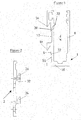
- the Figures 1, 2 and 3 illustrate a first embodiment of the invention.
- the figure 1 is a cross sectional view of a first section, said U-shaped section (referenced 1).
- the figure 2 is a view similar to that of the figure 1 showing a second section, called counter plate (referenced 2).
- the name "profiled” is given the meaning of "elongate piece whose transverse profile is essentially constant over the entire length of the piece.”
- the profiles which are the subject of the present description are preferably obtained by extrusion of an aluminum bar.
- the profiles of Figures 1 and 2 can have a length of 5 or 6 meters and a height of the order of 20 centimeters.
- the U-shaped section has a longitudinal groove 4 delimited by a thick side wall 6, a second thin side wall 8 and a bottom or base 10.
- the groove 4 opens upwards. Note that the expressions “up”, “down”, “on”, “under”, “above”, “below”, “below”, “above”, etc. are to be understood with reference to the orientation of the parts in the accompanying drawings.
- the outer face of the wall 6 has a very rugged profile. More specifically, the outer face of the wall 6 is hollowed out by two large parallel longitudinal grooves which are respectively referenced 12 and 14.
- the cross section of the figure 1 shows that the two furrows have substantially the same asymmetrical shape. It may be noted in particular that each of the grooves is delimited on one side by an upper dovetail edge and on the other side by a lower right edge.
- the bottom of each of the grooves has a small shoulder (respectively referenced 20 and 22) which separates a lower portion of the groove excavated deeper, an upper part a little shallower.
- the cross section of the figure 1 still shows, above each groove 12 or 14, a hook-shaped overhang constituted by the upper dovetail edge of the groove.
- the two hook-shaped overhangs respectively referenced 16 and 18, extend longitudinally over the entire length of the U-shaped section. It will be seen now that these two overhangs, or hooks, are arranged to cooperate with complementary elements that has one of the faces of the counterplate 2.
- the second section has the shape of a relatively thin plate, one of which faces flat, while the other has a very uneven profile.
- the uneven face is configured to fit the profile of the face of the U-shaped section which comprises the two hooks 16 and 18.
- the uneven side of the counter plate has two parallel longitudinal ribs (respectively referenced 24 and 26).
- the cross section of the figure 2 shows that the two ribs have similar profiles. It may be noted in particular that a longitudinal notch is dug in each of the ribs, the notch opening upwards. It will be understood that the form complementary of the two parts 1 and 2 allow to enter the two ribs 24, 26 in the two grooves 12, 14 of the U-section. Once the longitudinal ribs introduced two corresponding grooves, simply drag the U-shaped to the bottom parallel to the face of the against-plate so that the two hook-shaped portions 16, 18 respectively engage in the two notches so as to hook to the ribs 24, 26.
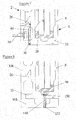
- the figure 3 is a cross-sectional view showing in particular the U-shaped section 1 and the counterplate 2 in the assembled position.
- the first and second profiles are perfectly adjusted.
- the ribs 24 and 26 completely fill the upper part of the two grooves 12, 14.
- the adjustment of the counterplate against the U-shaped section has the effect of completely covering the two grooves, showing two longitudinal cavities at the place occupied by the lower parts of the furrows.
- the figure 3 still shows two bolts 28, 30 arranged to fix the counter plate 2 at the head of slab or against a wall. It should be noted that although the cross section of the figure 3 only shows two bolts, the counterplate is normally fastened with a much larger number of bolts.
- the rib 24 has on its lower part a biased extension referenced 32.
- the extension 32 is part of the locking means according to the invention.
- a grub screw 34 which is inserted into a threaded through hole 33 of the U-shaped section. It can be seen that the end of the screw 34 protrudes from the through-hole and extends obliquely under the rib 24, tangentially to the slanting surface of the extension 32. It will be understood that extending under the extension of the rib 24, the screw 34 prevents any downward movement of the plate against the U-shaped section. It is therefore not possible to pick up the U-profile of the backplate without first unscrewing the screw 34.
- the figure 3 shows only one screw 34, one can for example provide locking screws every 36 cm over the entire length of the profile.
- the screw 34 extends obliquely. Indeed, the threaded through hole in which is inserted the screw 34 is oriented obliquely. It is preferable to orient the axis of the through hole so that a line extending the axis of the through hole does not cut the wall 8, but out of the U-shaped section through the opening of the groove 4. Such an arrangement has the advantage of providing sufficient clearance to allow access to the screw without problem with a screwdriver.
- the glass panels 36 can be installed.
- it can be large laminated glass panels typically constituted by the assembly of two plates. of glass having, for example, each a thickness of 12mm.
- PVC wedges 38 are placed at the bottom of the groove under the lower part of the glass panels 36.
- the U-shaped wedging pieces 38 are 20 cm long and are placed under the panels. glass at the joints between two panels.
- the glass panels 36 are then wedged with a PVC blocking wedge 40, then they are immobilized with two joints neoprene 42, 44.
- the Figures 4, 5 and 6 illustrate a second embodiment of the invention.
- the figure 4 is a cross sectional view of a U-shaped profile identical to that described in connection with the first embodiment.
- the figure 5 is a view similar to that of the figure 4 showing a counter-plate (referenced 102) arranged to be fixed on the top of a slab.
- a large number of elements entering the second embodiment are identical to the corresponding elements of the first embodiment. When the elements are identical, they are designated by the same reference number.
- the second profile has the shape of an L-shaped bracket comprising a horizontal fixing portion 104 and a vertical attachment portion 106.
- the top of the horizontal portion 104 is hollowed by a longitudinal groove 108.
- the vertical portion 106 has the general shape of a plate whose profile is oriented vertically. One of the faces of the portion 106 is flat, while the other has a very rugged profile.
- the rough side of the portion 106 is identical to the rough side of the back plate 2 of the first embodiment.
- the hook-shaped portions 16, 18 of the U-shaped section are arranged to hook onto the ribs 24, 26 of the vertical part of the counterplate 102.
- the figure 6 is a cross-sectional view showing in particular the U-profile 1 and the counter-plate 102 in the assembled position.
- the first and the second section are perfectly adjusted.
- the two complementary vertical faces of the first and second section are perfectly adjusted.
- the underside of the base 10 of the U-profile is perfectly adjusted with the top of the horizontal portion 104 of the counterplate.
- the adjustment of the base of the U-shaped section on the top of the portion 104 has the effect of completely covering the groove 108, revealing a longitudinal cavity at the location occupied by the groove 108.
- a bolt 110 arranged to fix the against-plate 102 on top of a slab.
- the figure 6 shows only a bolt 110, it will preferably provide bolts evenly spaced over the entire length of the profile.
- the figure 7 is an enlarged partial view in cross section showing an alternative variant of the locking means according to the invention.
- This variant lends itself to being implemented with the first embodiment.
- the locking screw 34 inserted obliquely is replaced by a screw 48 oriented vertically.
- the screw 48 is inserted into a threaded through hole 50 drilled in the base 10 of the U-shaped section. It can be seen that the screw 48 protrudes from the through-hole and extends upwards until it abuts against the underside of the rib 26 It will be understood that, extending as far as the rib 26, the screw 48 prevents any movement of the counter-plate downwards relative to the U-shaped section. It is therefore not possible to unhook the U-shaped section. against the plate without first unscrewing the screw 48.
- the figure 8 is an enlarged partial view in cross section showing a second alternative variant of the locking means according to the invention.
- This variant lends itself to being implemented with the second embodiment.
- the locking screw 34 inserted obliquely is replaced by a screw 148 oriented vertically.
- the screw 148 is inserted into a through hole 150 pierced in the base 10 of the U-shaped section.
- a threaded hole 152 is formed in the horizontal portion 104 of the counter-plate 102, in the extension of the hole 150 through it.
- the screw 148 has the effect of securing the base of the U-profile to the horizontal part of the backplate. It is therefore not possible to unhook the U-profile from the backplate without first unscrewing the screw 148.
Landscapes
- Engineering & Computer Science (AREA)
- Architecture (AREA)
- Civil Engineering (AREA)
- Structural Engineering (AREA)
- Securing Of Glass Panes Or The Like (AREA)
Applications Claiming Priority (1)
| Application Number | Priority Date | Filing Date | Title |
|---|---|---|---|
| CH01173/14A CH709956A2 (fr) | 2014-07-31 | 2014-07-31 | Dispositif pour fixer des panneaux en verre formant une balustrade. |
Publications (2)
| Publication Number | Publication Date |
|---|---|
| EP2980331A1 true EP2980331A1 (de) | 2016-02-03 |
| EP2980331B1 EP2980331B1 (de) | 2019-03-27 |
Family
ID=54196762
Family Applications (1)
| Application Number | Title | Priority Date | Filing Date |
|---|---|---|---|
| EP15179145.6A Not-in-force EP2980331B1 (de) | 2014-07-31 | 2015-07-30 | Vorrichtung zum befestigen von glaspaneelen, die eine brüstung bilden |
Country Status (2)
| Country | Link |
|---|---|
| EP (1) | EP2980331B1 (de) |
| CH (1) | CH709956A2 (de) |
Cited By (5)
| Publication number | Priority date | Publication date | Assignee | Title |
|---|---|---|---|---|
| DE102017119802A1 (de) * | 2017-08-29 | 2019-09-05 | Glas Trösch GmbH | Befestigungsvorrichtung |
| WO2022198244A1 (de) * | 2021-03-24 | 2022-09-29 | Gebr. Trettler Gmbh | Montagesystem fuer gelaender und absturzsicherungen |
| CN115306099A (zh) * | 2022-09-03 | 2022-11-08 | 北京亿尊装饰工程有限公司 | 一种玻璃护栏安装结构及施工方法 |
| US20230313524A1 (en) * | 2022-04-05 | 2023-10-05 | Pure Vista Ltd | Wood mounting system |
| DE102023117465A1 (de) * | 2023-07-03 | 2025-01-09 | Flynn GmbH | Profilsystem |
Citations (4)
| Publication number | Priority date | Publication date | Assignee | Title |
|---|---|---|---|---|
| WO2009123443A1 (en) * | 2008-04-03 | 2009-10-08 | Pol Balkonhekken B.V. | Profile beam |
| DE202012103568U1 (de) * | 2011-09-20 | 2012-11-12 | Sisukas OÜ | Montageprofil und Paneel-Schiene |
| EP2597220A1 (de) * | 2011-11-23 | 2013-05-29 | Bernhard Feigl | Vorrichtung zur Abstützung von Platten |
| WO2015092701A1 (en) * | 2013-12-17 | 2015-06-25 | Anjo Konsult Ab | Attachment for glass railing |
-
2014
- 2014-07-31 CH CH01173/14A patent/CH709956A2/fr not_active Application Discontinuation
-
2015
- 2015-07-30 EP EP15179145.6A patent/EP2980331B1/de not_active Not-in-force
Patent Citations (4)
| Publication number | Priority date | Publication date | Assignee | Title |
|---|---|---|---|---|
| WO2009123443A1 (en) * | 2008-04-03 | 2009-10-08 | Pol Balkonhekken B.V. | Profile beam |
| DE202012103568U1 (de) * | 2011-09-20 | 2012-11-12 | Sisukas OÜ | Montageprofil und Paneel-Schiene |
| EP2597220A1 (de) * | 2011-11-23 | 2013-05-29 | Bernhard Feigl | Vorrichtung zur Abstützung von Platten |
| WO2015092701A1 (en) * | 2013-12-17 | 2015-06-25 | Anjo Konsult Ab | Attachment for glass railing |
Cited By (7)
| Publication number | Priority date | Publication date | Assignee | Title |
|---|---|---|---|---|
| DE102017119802A1 (de) * | 2017-08-29 | 2019-09-05 | Glas Trösch GmbH | Befestigungsvorrichtung |
| WO2022198244A1 (de) * | 2021-03-24 | 2022-09-29 | Gebr. Trettler Gmbh | Montagesystem fuer gelaender und absturzsicherungen |
| AT524849B1 (de) * | 2021-03-24 | 2022-10-15 | Gebr Trettler Gmbh | Montagesystem für Geländer und Absturzsicherungen |
| AT524849A4 (de) * | 2021-03-24 | 2022-10-15 | Gebr Trettler Gmbh | Montagesystem für Geländer und Absturzsicherungen |
| US20230313524A1 (en) * | 2022-04-05 | 2023-10-05 | Pure Vista Ltd | Wood mounting system |
| CN115306099A (zh) * | 2022-09-03 | 2022-11-08 | 北京亿尊装饰工程有限公司 | 一种玻璃护栏安装结构及施工方法 |
| DE102023117465A1 (de) * | 2023-07-03 | 2025-01-09 | Flynn GmbH | Profilsystem |
Also Published As
| Publication number | Publication date |
|---|---|
| CH709956A2 (fr) | 2016-02-15 |
| EP2980331B1 (de) | 2019-03-27 |
Similar Documents
| Publication | Publication Date | Title |
|---|---|---|
| EP2980331B1 (de) | Vorrichtung zum befestigen von glaspaneelen, die eine brüstung bilden | |
| EP0343071B1 (de) | Tragstruktur zur auskragenden Befestigung eines Sanitärelements und ihre Stützpfosten | |
| BE1022779A1 (fr) | Systeme d'assemblage de panneaux suivant un diedre pour realiser un meuble et meuble ainsi realise | |
| EP2486195B1 (de) | Rahmen zur befestigung von platten zur herstellung einer wand oder trennwand | |
| FR3000120A1 (fr) | Cale de rupture thermique et electrolytique pour equerre de fixation murale d’un panneau de parement | |
| FR2800768A1 (fr) | Dispositif pour le montage et l'immobilisation de consoles de support sur une facade de batiment ou analogue | |
| EP4352332B1 (de) | Keil mit einstellbarer dicke | |
| EP2206869B1 (de) | Vorrichtung für die Motorisierung eines Fensters oder des Öffnungselements eines Schiebefensters | |
| FR3065980B1 (fr) | Systeme d’habillage d’un bord d'ouverture dans une cloison | |
| EP3296499B1 (de) | Versteckte fensterrahmen und verfahren zur herstellung desselben | |
| EP2317245A1 (de) | Montageeinheit von Geländer und Sonnenkollektor | |
| FR2953865A1 (fr) | Element de caniveau ouvert prefabrique | |
| EP3069637A1 (de) | Haltevorrichtung für stangen, die auf der vorderseite von jalousiekästen angepasst werden kann | |
| FR3056626A1 (fr) | Structure de verriere equipee d'un profile d'angle | |
| FR2833630A1 (fr) | Glissiere de securite bois | |
| FR2974164A1 (fr) | Installation solaire avec dispositif de fixation sur une structure support en pente | |
| FR3113297A1 (fr) | Coffre de volet roulant équipé d’une structure longitudinale de renfort intérieure | |
| FR2935451A1 (fr) | Ferrure d'assemblage multifonction | |
| FR2896143A1 (fr) | Dispositif de fixation pour barre d'accrochage d'ustensiles de cuisine forme essentiellement d'un support-equerre et d'un cavalier de blocage | |
| WO2024132748A1 (fr) | Panneau de facade de batiment et son procede d'installation | |
| EP2674550A1 (de) | Versteifungselement für die Befestigung einer Schwimmbadwand, Befestigungsanordnung, Schwimmbad uund Methode zum Bau eines solchen Schwimmbads | |
| EP4397836A1 (de) | Rolladensystem zur montage an einem rahmen eines gebäudes | |
| FR3165279A1 (fr) | Garde-corps comprenant une plaque de remplissage en tôle fixée sur des montants et des lisses de remplissage | |
| EP2492414A1 (de) | Modulares Geländer mit Regulierungsvorrichtung, und Modulbestandteil eines solchen Geländers | |
| FR3145942A1 (fr) | Système de fixation pour poteau comportant un système anti-soulèvement |
Legal Events
| Date | Code | Title | Description |
|---|---|---|---|
| PUAI | Public reference made under article 153(3) epc to a published international application that has entered the european phase |
Free format text: ORIGINAL CODE: 0009012 |
|
| AK | Designated contracting states |
Kind code of ref document: A1 Designated state(s): AL AT BE BG CH CY CZ DE DK EE ES FI FR GB GR HR HU IE IS IT LI LT LU LV MC MK MT NL NO PL PT RO RS SE SI SK SM TR |
|
| AX | Request for extension of the european patent |
Extension state: BA ME |
|
| 17P | Request for examination filed |
Effective date: 20160722 |
|
| RBV | Designated contracting states (corrected) |
Designated state(s): AL AT BE BG CH CY CZ DE DK EE ES FI FR GB GR HR HU IE IS IT LI LT LU LV MC MK MT NL NO PL PT RO RS SE SI SK SM TR |
|
| STAA | Information on the status of an ep patent application or granted ep patent |
Free format text: STATUS: EXAMINATION IS IN PROGRESS |
|
| 17Q | First examination report despatched |
Effective date: 20171207 |
|
| GRAP | Despatch of communication of intention to grant a patent |
Free format text: ORIGINAL CODE: EPIDOSNIGR1 |
|
| STAA | Information on the status of an ep patent application or granted ep patent |
Free format text: STATUS: GRANT OF PATENT IS INTENDED |
|
| INTG | Intention to grant announced |
Effective date: 20181023 |
|
| GRAS | Grant fee paid |
Free format text: ORIGINAL CODE: EPIDOSNIGR3 |
|
| GRAA | (expected) grant |
Free format text: ORIGINAL CODE: 0009210 |
|
| STAA | Information on the status of an ep patent application or granted ep patent |
Free format text: STATUS: THE PATENT HAS BEEN GRANTED |
|
| AK | Designated contracting states |
Kind code of ref document: B1 Designated state(s): AL AT BE BG CH CY CZ DE DK EE ES FI FR GB GR HR HU IE IS IT LI LT LU LV MC MK MT NL NO PL PT RO RS SE SI SK SM TR |
|
| REG | Reference to a national code |
Ref country code: GB Ref legal event code: FG4D Free format text: NOT ENGLISH |
|
| REG | Reference to a national code |
Ref country code: CH Ref legal event code: EP |
|
| REG | Reference to a national code |
Ref country code: AT Ref legal event code: REF Ref document number: 1113260 Country of ref document: AT Kind code of ref document: T Effective date: 20190415 |
|
| REG | Reference to a national code |
Ref country code: IE Ref legal event code: FG4D Free format text: LANGUAGE OF EP DOCUMENT: FRENCH |
|
| REG | Reference to a national code |
Ref country code: DE Ref legal event code: R096 Ref document number: 602015027032 Country of ref document: DE |
|
| REG | Reference to a national code |
Ref country code: CH Ref legal event code: NV Representative=s name: MICHELI AND CIE SA, CH |
|
| PG25 | Lapsed in a contracting state [announced via postgrant information from national office to epo] |
Ref country code: NO Free format text: LAPSE BECAUSE OF FAILURE TO SUBMIT A TRANSLATION OF THE DESCRIPTION OR TO PAY THE FEE WITHIN THE PRESCRIBED TIME-LIMIT Effective date: 20190627 Ref country code: SE Free format text: LAPSE BECAUSE OF FAILURE TO SUBMIT A TRANSLATION OF THE DESCRIPTION OR TO PAY THE FEE WITHIN THE PRESCRIBED TIME-LIMIT Effective date: 20190327 Ref country code: LT Free format text: LAPSE BECAUSE OF FAILURE TO SUBMIT A TRANSLATION OF THE DESCRIPTION OR TO PAY THE FEE WITHIN THE PRESCRIBED TIME-LIMIT Effective date: 20190327 Ref country code: FI Free format text: LAPSE BECAUSE OF FAILURE TO SUBMIT A TRANSLATION OF THE DESCRIPTION OR TO PAY THE FEE WITHIN THE PRESCRIBED TIME-LIMIT Effective date: 20190327 |
|
| REG | Reference to a national code |
Ref country code: NL Ref legal event code: MP Effective date: 20190327 |
|
| PG25 | Lapsed in a contracting state [announced via postgrant information from national office to epo] |
Ref country code: HR Free format text: LAPSE BECAUSE OF FAILURE TO SUBMIT A TRANSLATION OF THE DESCRIPTION OR TO PAY THE FEE WITHIN THE PRESCRIBED TIME-LIMIT Effective date: 20190327 Ref country code: NL Free format text: LAPSE BECAUSE OF FAILURE TO SUBMIT A TRANSLATION OF THE DESCRIPTION OR TO PAY THE FEE WITHIN THE PRESCRIBED TIME-LIMIT Effective date: 20190327 Ref country code: RS Free format text: LAPSE BECAUSE OF FAILURE TO SUBMIT A TRANSLATION OF THE DESCRIPTION OR TO PAY THE FEE WITHIN THE PRESCRIBED TIME-LIMIT Effective date: 20190327 Ref country code: BG Free format text: LAPSE BECAUSE OF FAILURE TO SUBMIT A TRANSLATION OF THE DESCRIPTION OR TO PAY THE FEE WITHIN THE PRESCRIBED TIME-LIMIT Effective date: 20190627 Ref country code: LV Free format text: LAPSE BECAUSE OF FAILURE TO SUBMIT A TRANSLATION OF THE DESCRIPTION OR TO PAY THE FEE WITHIN THE PRESCRIBED TIME-LIMIT Effective date: 20190327 Ref country code: GR Free format text: LAPSE BECAUSE OF FAILURE TO SUBMIT A TRANSLATION OF THE DESCRIPTION OR TO PAY THE FEE WITHIN THE PRESCRIBED TIME-LIMIT Effective date: 20190628 |
|
| REG | Reference to a national code |
Ref country code: AT Ref legal event code: MK05 Ref document number: 1113260 Country of ref document: AT Kind code of ref document: T Effective date: 20190327 |
|
| PG25 | Lapsed in a contracting state [announced via postgrant information from national office to epo] |
Ref country code: EE Free format text: LAPSE BECAUSE OF FAILURE TO SUBMIT A TRANSLATION OF THE DESCRIPTION OR TO PAY THE FEE WITHIN THE PRESCRIBED TIME-LIMIT Effective date: 20190327 Ref country code: IT Free format text: LAPSE BECAUSE OF FAILURE TO SUBMIT A TRANSLATION OF THE DESCRIPTION OR TO PAY THE FEE WITHIN THE PRESCRIBED TIME-LIMIT Effective date: 20190327 Ref country code: SK Free format text: LAPSE BECAUSE OF FAILURE TO SUBMIT A TRANSLATION OF THE DESCRIPTION OR TO PAY THE FEE WITHIN THE PRESCRIBED TIME-LIMIT Effective date: 20190327 Ref country code: AL Free format text: LAPSE BECAUSE OF FAILURE TO SUBMIT A TRANSLATION OF THE DESCRIPTION OR TO PAY THE FEE WITHIN THE PRESCRIBED TIME-LIMIT Effective date: 20190327 Ref country code: PT Free format text: LAPSE BECAUSE OF FAILURE TO SUBMIT A TRANSLATION OF THE DESCRIPTION OR TO PAY THE FEE WITHIN THE PRESCRIBED TIME-LIMIT Effective date: 20190727 Ref country code: CZ Free format text: LAPSE BECAUSE OF FAILURE TO SUBMIT A TRANSLATION OF THE DESCRIPTION OR TO PAY THE FEE WITHIN THE PRESCRIBED TIME-LIMIT Effective date: 20190327 Ref country code: RO Free format text: LAPSE BECAUSE OF FAILURE TO SUBMIT A TRANSLATION OF THE DESCRIPTION OR TO PAY THE FEE WITHIN THE PRESCRIBED TIME-LIMIT Effective date: 20190327 Ref country code: ES Free format text: LAPSE BECAUSE OF FAILURE TO SUBMIT A TRANSLATION OF THE DESCRIPTION OR TO PAY THE FEE WITHIN THE PRESCRIBED TIME-LIMIT Effective date: 20190327 |
|
| PG25 | Lapsed in a contracting state [announced via postgrant information from national office to epo] |
Ref country code: SM Free format text: LAPSE BECAUSE OF FAILURE TO SUBMIT A TRANSLATION OF THE DESCRIPTION OR TO PAY THE FEE WITHIN THE PRESCRIBED TIME-LIMIT Effective date: 20190327 Ref country code: PL Free format text: LAPSE BECAUSE OF FAILURE TO SUBMIT A TRANSLATION OF THE DESCRIPTION OR TO PAY THE FEE WITHIN THE PRESCRIBED TIME-LIMIT Effective date: 20190327 |
|
| PG25 | Lapsed in a contracting state [announced via postgrant information from national office to epo] |
Ref country code: AT Free format text: LAPSE BECAUSE OF FAILURE TO SUBMIT A TRANSLATION OF THE DESCRIPTION OR TO PAY THE FEE WITHIN THE PRESCRIBED TIME-LIMIT Effective date: 20190327 Ref country code: IS Free format text: LAPSE BECAUSE OF FAILURE TO SUBMIT A TRANSLATION OF THE DESCRIPTION OR TO PAY THE FEE WITHIN THE PRESCRIBED TIME-LIMIT Effective date: 20190727 |
|
| REG | Reference to a national code |
Ref country code: DE Ref legal event code: R097 Ref document number: 602015027032 Country of ref document: DE |
|
| PG25 | Lapsed in a contracting state [announced via postgrant information from national office to epo] |
Ref country code: DK Free format text: LAPSE BECAUSE OF FAILURE TO SUBMIT A TRANSLATION OF THE DESCRIPTION OR TO PAY THE FEE WITHIN THE PRESCRIBED TIME-LIMIT Effective date: 20190327 |
|
| PLBE | No opposition filed within time limit |
Free format text: ORIGINAL CODE: 0009261 |
|
| STAA | Information on the status of an ep patent application or granted ep patent |
Free format text: STATUS: NO OPPOSITION FILED WITHIN TIME LIMIT |
|
| PG25 | Lapsed in a contracting state [announced via postgrant information from national office to epo] |
Ref country code: MC Free format text: LAPSE BECAUSE OF FAILURE TO SUBMIT A TRANSLATION OF THE DESCRIPTION OR TO PAY THE FEE WITHIN THE PRESCRIBED TIME-LIMIT Effective date: 20190327 Ref country code: SI Free format text: LAPSE BECAUSE OF FAILURE TO SUBMIT A TRANSLATION OF THE DESCRIPTION OR TO PAY THE FEE WITHIN THE PRESCRIBED TIME-LIMIT Effective date: 20190327 |
|
| 26N | No opposition filed |
Effective date: 20200103 |
|
| GBPC | Gb: european patent ceased through non-payment of renewal fee |
Effective date: 20190730 |
|
| PG25 | Lapsed in a contracting state [announced via postgrant information from national office to epo] |
Ref country code: TR Free format text: LAPSE BECAUSE OF FAILURE TO SUBMIT A TRANSLATION OF THE DESCRIPTION OR TO PAY THE FEE WITHIN THE PRESCRIBED TIME-LIMIT Effective date: 20190327 |
|
| PG25 | Lapsed in a contracting state [announced via postgrant information from national office to epo] |
Ref country code: GB Free format text: LAPSE BECAUSE OF NON-PAYMENT OF DUE FEES Effective date: 20190730 |
|
| PG25 | Lapsed in a contracting state [announced via postgrant information from national office to epo] |
Ref country code: LU Free format text: LAPSE BECAUSE OF NON-PAYMENT OF DUE FEES Effective date: 20190730 |
|
| PG25 | Lapsed in a contracting state [announced via postgrant information from national office to epo] |
Ref country code: IE Free format text: LAPSE BECAUSE OF NON-PAYMENT OF DUE FEES Effective date: 20190730 |
|
| PG25 | Lapsed in a contracting state [announced via postgrant information from national office to epo] |
Ref country code: CY Free format text: LAPSE BECAUSE OF FAILURE TO SUBMIT A TRANSLATION OF THE DESCRIPTION OR TO PAY THE FEE WITHIN THE PRESCRIBED TIME-LIMIT Effective date: 20190327 |
|
| PG25 | Lapsed in a contracting state [announced via postgrant information from national office to epo] |
Ref country code: HU Free format text: LAPSE BECAUSE OF FAILURE TO SUBMIT A TRANSLATION OF THE DESCRIPTION OR TO PAY THE FEE WITHIN THE PRESCRIBED TIME-LIMIT; INVALID AB INITIO Effective date: 20150730 Ref country code: MT Free format text: LAPSE BECAUSE OF FAILURE TO SUBMIT A TRANSLATION OF THE DESCRIPTION OR TO PAY THE FEE WITHIN THE PRESCRIBED TIME-LIMIT Effective date: 20190327 |
|
| PGFP | Annual fee paid to national office [announced via postgrant information from national office to epo] |
Ref country code: FR Payment date: 20210729 Year of fee payment: 7 |
|
| PGFP | Annual fee paid to national office [announced via postgrant information from national office to epo] |
Ref country code: CH Payment date: 20210729 Year of fee payment: 7 Ref country code: BE Payment date: 20210721 Year of fee payment: 7 Ref country code: DE Payment date: 20210721 Year of fee payment: 7 |
|
| PG25 | Lapsed in a contracting state [announced via postgrant information from national office to epo] |
Ref country code: MK Free format text: LAPSE BECAUSE OF FAILURE TO SUBMIT A TRANSLATION OF THE DESCRIPTION OR TO PAY THE FEE WITHIN THE PRESCRIBED TIME-LIMIT Effective date: 20190327 |
|
| REG | Reference to a national code |
Ref country code: DE Ref legal event code: R119 Ref document number: 602015027032 Country of ref document: DE |
|
| REG | Reference to a national code |
Ref country code: CH Ref legal event code: PL |
|
| REG | Reference to a national code |
Ref country code: BE Ref legal event code: MM Effective date: 20220731 |
|
| PG25 | Lapsed in a contracting state [announced via postgrant information from national office to epo] |
Ref country code: LI Free format text: LAPSE BECAUSE OF NON-PAYMENT OF DUE FEES Effective date: 20220731 Ref country code: FR Free format text: LAPSE BECAUSE OF NON-PAYMENT OF DUE FEES Effective date: 20220731 Ref country code: CH Free format text: LAPSE BECAUSE OF NON-PAYMENT OF DUE FEES Effective date: 20220731 |
|
| PG25 | Lapsed in a contracting state [announced via postgrant information from national office to epo] |
Ref country code: DE Free format text: LAPSE BECAUSE OF NON-PAYMENT OF DUE FEES Effective date: 20230201 Ref country code: BE Free format text: LAPSE BECAUSE OF NON-PAYMENT OF DUE FEES Effective date: 20220731 |