EP2980366A1 - Gehäuse für eine gasturbine, flugtriebwerk sowie ein verfahren zum betreiben einer gasturbine - Google Patents
Gehäuse für eine gasturbine, flugtriebwerk sowie ein verfahren zum betreiben einer gasturbine Download PDFInfo
- Publication number
- EP2980366A1 EP2980366A1 EP15176353.9A EP15176353A EP2980366A1 EP 2980366 A1 EP2980366 A1 EP 2980366A1 EP 15176353 A EP15176353 A EP 15176353A EP 2980366 A1 EP2980366 A1 EP 2980366A1
- Authority
- EP
- European Patent Office
- Prior art keywords
- housing
- wall element
- gas turbine
- pressure
- open position
- Prior art date
- Legal status (The legal status is an assumption and is not a legal conclusion. Google has not performed a legal analysis and makes no representation as to the accuracy of the status listed.)
- Granted
Links
- 238000000034 method Methods 0.000 title claims abstract description 9
- 238000007789 sealing Methods 0.000 claims abstract description 61
- 239000012530 fluid Substances 0.000 claims description 14
- 238000007599 discharging Methods 0.000 claims description 3
- 230000001105 regulatory effect Effects 0.000 claims description 3
- 239000000446 fuel Substances 0.000 description 9
- 238000001816 cooling Methods 0.000 description 4
- 230000007704 transition Effects 0.000 description 3
- 230000006978 adaptation Effects 0.000 description 2
- 230000033228 biological regulation Effects 0.000 description 2
- 238000002485 combustion reaction Methods 0.000 description 2
- 239000011796 hollow space material Substances 0.000 description 2
- 238000012423 maintenance Methods 0.000 description 2
- 230000002441 reversible effect Effects 0.000 description 2
- 238000003860 storage Methods 0.000 description 2
- 230000002411 adverse Effects 0.000 description 1
- 238000005452 bending Methods 0.000 description 1
- 230000000740 bleeding effect Effects 0.000 description 1
- 238000010276 construction Methods 0.000 description 1
- 238000011161 development Methods 0.000 description 1
- 230000018109 developmental process Effects 0.000 description 1
- 238000005553 drilling Methods 0.000 description 1
- 230000000694 effects Effects 0.000 description 1
- 238000005562 fading Methods 0.000 description 1
- 230000006698 induction Effects 0.000 description 1
- 230000001939 inductive effect Effects 0.000 description 1
- 238000004519 manufacturing process Methods 0.000 description 1
- 238000013021 overheating Methods 0.000 description 1
- 238000005096 rolling process Methods 0.000 description 1
Images

Classifications
-
- F—MECHANICAL ENGINEERING; LIGHTING; HEATING; WEAPONS; BLASTING
- F01—MACHINES OR ENGINES IN GENERAL; ENGINE PLANTS IN GENERAL; STEAM ENGINES
- F01D—NON-POSITIVE DISPLACEMENT MACHINES OR ENGINES, e.g. STEAM TURBINES
- F01D17/00—Regulating or controlling by varying flow
- F01D17/20—Devices dealing with sensing elements or final actuators or transmitting means between them, e.g. power-assisted
- F01D17/22—Devices dealing with sensing elements or final actuators or transmitting means between them, e.g. power-assisted the operation or power assistance being predominantly non-mechanical
- F01D17/26—Devices dealing with sensing elements or final actuators or transmitting means between them, e.g. power-assisted the operation or power assistance being predominantly non-mechanical fluid, e.g. hydraulic
-
- F—MECHANICAL ENGINEERING; LIGHTING; HEATING; WEAPONS; BLASTING
- F01—MACHINES OR ENGINES IN GENERAL; ENGINE PLANTS IN GENERAL; STEAM ENGINES
- F01D—NON-POSITIVE DISPLACEMENT MACHINES OR ENGINES, e.g. STEAM TURBINES
- F01D11/00—Preventing or minimising internal leakage of working-fluid, e.g. between stages
- F01D11/001—Preventing or minimising internal leakage of working-fluid, e.g. between stages for sealing space between stator blade and rotor
-
- F—MECHANICAL ENGINEERING; LIGHTING; HEATING; WEAPONS; BLASTING
- F01—MACHINES OR ENGINES IN GENERAL; ENGINE PLANTS IN GENERAL; STEAM ENGINES
- F01D—NON-POSITIVE DISPLACEMENT MACHINES OR ENGINES, e.g. STEAM TURBINES
- F01D17/00—Regulating or controlling by varying flow
- F01D17/10—Final actuators
-
- F—MECHANICAL ENGINEERING; LIGHTING; HEATING; WEAPONS; BLASTING
- F01—MACHINES OR ENGINES IN GENERAL; ENGINE PLANTS IN GENERAL; STEAM ENGINES
- F01D—NON-POSITIVE DISPLACEMENT MACHINES OR ENGINES, e.g. STEAM TURBINES
- F01D17/00—Regulating or controlling by varying flow
- F01D17/10—Final actuators
- F01D17/12—Final actuators arranged in stator parts
- F01D17/14—Final actuators arranged in stator parts varying effective cross-sectional area of nozzles or guide conduits
- F01D17/16—Final actuators arranged in stator parts varying effective cross-sectional area of nozzles or guide conduits by means of nozzle vanes
- F01D17/162—Final actuators arranged in stator parts varying effective cross-sectional area of nozzles or guide conduits by means of nozzle vanes for axial flow, i.e. the vanes turning around axes which are essentially perpendicular to the rotor centre line
-
- F—MECHANICAL ENGINEERING; LIGHTING; HEATING; WEAPONS; BLASTING
- F01—MACHINES OR ENGINES IN GENERAL; ENGINE PLANTS IN GENERAL; STEAM ENGINES
- F01D—NON-POSITIVE DISPLACEMENT MACHINES OR ENGINES, e.g. STEAM TURBINES
- F01D25/00—Component parts, details, or accessories, not provided for in, or of interest apart from, other groups
- F01D25/16—Arrangement of bearings; Supporting or mounting bearings in casings
-
- F—MECHANICAL ENGINEERING; LIGHTING; HEATING; WEAPONS; BLASTING
- F01—MACHINES OR ENGINES IN GENERAL; ENGINE PLANTS IN GENERAL; STEAM ENGINES
- F01D—NON-POSITIVE DISPLACEMENT MACHINES OR ENGINES, e.g. STEAM TURBINES
- F01D25/00—Component parts, details, or accessories, not provided for in, or of interest apart from, other groups
- F01D25/24—Casings; Casing parts, e.g. diaphragms, casing fastenings
-
- F—MECHANICAL ENGINEERING; LIGHTING; HEATING; WEAPONS; BLASTING
- F01—MACHINES OR ENGINES IN GENERAL; ENGINE PLANTS IN GENERAL; STEAM ENGINES
- F01D—NON-POSITIVE DISPLACEMENT MACHINES OR ENGINES, e.g. STEAM TURBINES
- F01D9/00—Stators
- F01D9/02—Nozzles; Nozzle boxes; Stator blades; Guide conduits, e.g. individual nozzles
- F01D9/04—Nozzles; Nozzle boxes; Stator blades; Guide conduits, e.g. individual nozzles forming ring or sector
-
- F—MECHANICAL ENGINEERING; LIGHTING; HEATING; WEAPONS; BLASTING
- F01—MACHINES OR ENGINES IN GENERAL; ENGINE PLANTS IN GENERAL; STEAM ENGINES
- F01D—NON-POSITIVE DISPLACEMENT MACHINES OR ENGINES, e.g. STEAM TURBINES
- F01D9/00—Stators
- F01D9/02—Nozzles; Nozzle boxes; Stator blades; Guide conduits, e.g. individual nozzles
- F01D9/04—Nozzles; Nozzle boxes; Stator blades; Guide conduits, e.g. individual nozzles forming ring or sector
- F01D9/041—Nozzles; Nozzle boxes; Stator blades; Guide conduits, e.g. individual nozzles forming ring or sector using blades
-
- F—MECHANICAL ENGINEERING; LIGHTING; HEATING; WEAPONS; BLASTING
- F04—POSITIVE - DISPLACEMENT MACHINES FOR LIQUIDS; PUMPS FOR LIQUIDS OR ELASTIC FLUIDS
- F04D—NON-POSITIVE-DISPLACEMENT PUMPS
- F04D29/00—Details, component parts, or accessories
- F04D29/08—Sealings
- F04D29/083—Sealings especially adapted for elastic fluid pumps
-
- F—MECHANICAL ENGINEERING; LIGHTING; HEATING; WEAPONS; BLASTING
- F04—POSITIVE - DISPLACEMENT MACHINES FOR LIQUIDS; PUMPS FOR LIQUIDS OR ELASTIC FLUIDS
- F04D—NON-POSITIVE-DISPLACEMENT PUMPS
- F04D29/00—Details, component parts, or accessories
- F04D29/08—Sealings
- F04D29/16—Sealings between pressure and suction sides
- F04D29/161—Sealings between pressure and suction sides especially adapted for elastic fluid pumps
-
- F—MECHANICAL ENGINEERING; LIGHTING; HEATING; WEAPONS; BLASTING
- F04—POSITIVE - DISPLACEMENT MACHINES FOR LIQUIDS; PUMPS FOR LIQUIDS OR ELASTIC FLUIDS
- F04D—NON-POSITIVE-DISPLACEMENT PUMPS
- F04D29/00—Details, component parts, or accessories
- F04D29/40—Casings; Connections of working fluid
- F04D29/52—Casings; Connections of working fluid for axial pumps
- F04D29/54—Fluid-guiding means, e.g. diffusers
- F04D29/56—Fluid-guiding means, e.g. diffusers adjustable
- F04D29/563—Fluid-guiding means, e.g. diffusers adjustable specially adapted for elastic fluid pumps
-
- F—MECHANICAL ENGINEERING; LIGHTING; HEATING; WEAPONS; BLASTING
- F01—MACHINES OR ENGINES IN GENERAL; ENGINE PLANTS IN GENERAL; STEAM ENGINES
- F01D—NON-POSITIVE DISPLACEMENT MACHINES OR ENGINES, e.g. STEAM TURBINES
- F01D11/00—Preventing or minimising internal leakage of working-fluid, e.g. between stages
- F01D11/08—Preventing or minimising internal leakage of working-fluid, e.g. between stages for sealing space between rotor blade tips and stator
- F01D11/14—Adjusting or regulating tip-clearance, i.e. distance between rotor-blade tips and stator casing
- F01D11/20—Actively adjusting tip-clearance
- F01D11/22—Actively adjusting tip-clearance by mechanically actuating the stator or rotor components, e.g. moving shroud sections relative to the rotor
-
- F—MECHANICAL ENGINEERING; LIGHTING; HEATING; WEAPONS; BLASTING
- F05—INDEXING SCHEMES RELATING TO ENGINES OR PUMPS IN VARIOUS SUBCLASSES OF CLASSES F01-F04
- F05D—INDEXING SCHEME FOR ASPECTS RELATING TO NON-POSITIVE-DISPLACEMENT MACHINES OR ENGINES, GAS-TURBINES OR JET-PROPULSION PLANTS
- F05D2220/00—Application
- F05D2220/30—Application in turbines
- F05D2220/32—Application in turbines in gas turbines
-
- F—MECHANICAL ENGINEERING; LIGHTING; HEATING; WEAPONS; BLASTING
- F05—INDEXING SCHEMES RELATING TO ENGINES OR PUMPS IN VARIOUS SUBCLASSES OF CLASSES F01-F04
- F05D—INDEXING SCHEME FOR ASPECTS RELATING TO NON-POSITIVE-DISPLACEMENT MACHINES OR ENGINES, GAS-TURBINES OR JET-PROPULSION PLANTS
- F05D2240/00—Components
- F05D2240/10—Stators
- F05D2240/12—Fluid guiding means, e.g. vanes
-
- F—MECHANICAL ENGINEERING; LIGHTING; HEATING; WEAPONS; BLASTING
- F05—INDEXING SCHEMES RELATING TO ENGINES OR PUMPS IN VARIOUS SUBCLASSES OF CLASSES F01-F04
- F05D—INDEXING SCHEME FOR ASPECTS RELATING TO NON-POSITIVE-DISPLACEMENT MACHINES OR ENGINES, GAS-TURBINES OR JET-PROPULSION PLANTS
- F05D2240/00—Components
- F05D2240/55—Seals
-
- F—MECHANICAL ENGINEERING; LIGHTING; HEATING; WEAPONS; BLASTING
- F05—INDEXING SCHEMES RELATING TO ENGINES OR PUMPS IN VARIOUS SUBCLASSES OF CLASSES F01-F04
- F05D—INDEXING SCHEME FOR ASPECTS RELATING TO NON-POSITIVE-DISPLACEMENT MACHINES OR ENGINES, GAS-TURBINES OR JET-PROPULSION PLANTS
- F05D2270/00—Control
- F05D2270/60—Control system actuates means
- F05D2270/65—Pneumatic actuators
-
- Y—GENERAL TAGGING OF NEW TECHNOLOGICAL DEVELOPMENTS; GENERAL TAGGING OF CROSS-SECTIONAL TECHNOLOGIES SPANNING OVER SEVERAL SECTIONS OF THE IPC; TECHNICAL SUBJECTS COVERED BY FORMER USPC CROSS-REFERENCE ART COLLECTIONS [XRACs] AND DIGESTS
- Y02—TECHNOLOGIES OR APPLICATIONS FOR MITIGATION OR ADAPTATION AGAINST CLIMATE CHANGE
- Y02T—CLIMATE CHANGE MITIGATION TECHNOLOGIES RELATED TO TRANSPORTATION
- Y02T50/00—Aeronautics or air transport
- Y02T50/60—Efficient propulsion technologies, e.g. for aircraft
Definitions
- the invention relates to a housing for a gas turbine according to the preamble of claim 1. Furthermore, the invention relates to a gas turbine and a method for operating a gas turbine.
- Gas turbines with variably adjustable vanes are known from the prior art.
- vanes are rotatably mounted on a housing of the gas turbine for adjusting, wherein the vanes of the vanes are arranged in a flow channel of the housing of the gas turbine.
- Variable adjustable vanes in a gas turbine allow in particular the adaptation of the ability to swallow a turbine and the targeted adaptation of the flow of subsequent rotors. As a result, a gas turbine for different operating points can be set particularly well, which reduces fuel consumption.
- a housing for a gas turbine which comprises a plurality of wall elements in addition to variably adjustable vanes, which are movably mounted on the housing and acted upon by a spring with a force directed in the direction of the flow channel.
- Object of the present invention is to provide a housing for a gas turbine, which on the one hand enables a reliable guide vane adjustment and on the other hand, an improved efficiency of an associated gas turbine.
- Another object of the invention is to provide a gas turbine with such a housing and a method of operating a gas turbine with such a housing.
- a first aspect of the invention relates to a housing for a gas turbine.
- the wall element between a sealing position, in which the wall element at least on a portion of the wall element facing side of an airfoil of the vane, and an open position in which the airfoil and the wall element are spaced from each other is movable.
- the wall element is movable on the one hand in an open position in which a sufficiently large gap between the wall element and the blade of the vane is formed in order to adjust the guide vane can.
- the wall element is movable into a sealing position, in which the wall element facing the side of the blade of the vane at least partially rests against the wall element.
- the flag gap is thus partially, predominantly or completely closed, as a result of which corresponding throttling losses during operation of the associated gas turbine are greatly reduced or completely avoided.
- the efficiency of the associated gas turbine is improved, while on the other hand, the adjustability of the vane is still ensured.
- a sliding seal which could be realized for example by means of bristles, sliders or the like, there is moreover no wear on the adjustable airfoil or the wall element.
- the housing according to the invention is particularly low maintenance.
- the adjustable guide vane can basically be designed as a turbine guide vane or as a compressor vane. Furthermore, in principle, a plurality of adjustable guide vanes can be provided, which are arranged side by side in the circumferential direction of the housing to a guide vane ring. The adjustable guide vanes can also be combined to form vane segments. Analogously, a plurality of adjustable wall elements, which may also be referred to as annular space segments, be arranged side by side in the circumferential direction of the housing to a complete, the flow channel radially outwardly bounding ring.
- the wall element for moving between the open position and the sealing position with a pressurized fluid can be acted upon.
- the wall element together with other housing elements limit a pressurizable cavity.
- Pressurized fluids can be generated in gas turbines without any special effort.
- a fluid compressed air in the form of so-called bleed air from a compressor stage of the gas turbine can be tapped.
- the bleeding of bleed air or compressed air from the compressor of gas turbines is known per se and already provided in many aircraft engines. When using the gas turbine in an aircraft engine is, above a certain speed of an aircraft, helicopters or the like also a sufficient high air pressure in the form of back pressure available.
- the wall element can be subjected to pressure in a particularly simple and particularly cost-effective manner.
- the number of moving parts in particular in contrast to, for example, the use of an actuator, is particularly low.
- the housing and thus also provided with the housing gas turbine can be designed to be particularly low maintenance and easy. This is particularly important in aircraft construction.
- the hydraulic system which is likewise usually already provided, for example, for aircraft, can be used.
- the housing comprises a pressure feed line for supplying the pressurized fluid and a pressure discharge for discharging the pressurized fluid.
- the pressure on the wall element can be correspondingly increased by supplying the fluid under pressure, while the pressure on the wall element can be correspondingly reduced by discharging the fluid via the pressure discharge.
- the pressure feed line can form, for example, a channel to one of the compressor stages of the gas turbine.
- the pressure supply line form a channel to the surroundings of the gas turbine, so that the wall element can be acted upon by the ambient pressure.
- the pressure feed line is a passage opening in an aircraft engine, by means of which the wall element can be acted upon by the dynamic pressure generated by the movement of the aircraft, helicopter or the like.
- a movement of the wall element is effected in the closed position by an increased pressure, so that the flag gap during operation of an associated gas turbine is closed by default, at least for the most part.
- the movement of the Wandungselements in the open position is effected in this case by a relative pressure reduction or by a discharge of the pressurized fluid.
- the pressure discharge can lead into the environment. This movement can be assisted by a pressure in the flow channel, which acts on the wall element.
- the pressure supply line and / or the pressure discharge comprises a valve by means of which the pressure on the wall element is controllable and / or controllable.
- This allows a particularly precise control and / or regulation of the movement of the wall element between the sealing position and the open position.
- the control or regulation of the valve can take place as a function of operating parameters of the gas turbine.
- the valve may for example be coupled to a control and / or regulating device of the gas turbine.
- a Abblasskanal the pressure discharge has a larger cross-section than an access channel of the pressure supply line.
- the larger cross section of the Abblasskanals allows a particularly rapid pressure reduction and thus a particularly rapid movement of the wall element between the open and the sealing position. Moreover, this makes it possible to use only one valve at the pressure discharge and thus to keep the number of parts and the weight of the housing as low as possible. When the valve is opened, more fluid can be discharged via the pressure discharge due to the larger cross section of the Abblasskanals than can be supplied simultaneously via the pressure supply, whereby a rapid pressure reduction is achieved.
- the wall element is held on one side by a bearing on a housing element.
- the storage reduces at least one of the degrees of freedom of the movable wall element.
- the wall element can be moved via the bearing relative to the adjacent housing element and, for example, pivoted or bent between the sealing position and the open position.
- At least one sealing element is arranged between the wall element and an adjacent housing element.
- This allows a reliable sealing of a gap between the wall element and the adjacent housing element.
- Such a gap may arise in particular when moving the wall element between the sealing position and the open position.
- pressure losses in the flow channel can be particularly reliably prevented, so that the efficiency of the gas turbine is increased regardless of the position of the wall element.
- the sealing element can be arranged so that the wall element slides on a movement between the sealing position and the open position of the sealing element along.
- the sealing element may also be attached to the movable wall element and slide along the other housing element.
- the wall element comprises an opening in which the blade plate of the guide vane is arranged.
- a clearance fit is preferably provided between the blade plate and the opening, so that the guide blade and the wall element are movable relative to each other.
- the wall element can serve as a guide for the adjustable vane.
- the blade plate can serve as a guide when adjusting the wall element between the open and the sealing position.
- the wall element and the guide blade are fixed in the sealing position frictionally against each other. That is, the wall member in the sealing position exerts such a normal force on the engaged side of the vane blade that relative movement of the vane is prevented, at least under normal operating conditions of an associated gas turbine.
- This allows a particularly reliable, reversible position assurance of the guide vane, so that advantageously even an additional device for setting the variably adjustable guide vane can be dispensed with.
- the housing comprises at least one stop element which limits the movement of the wall element in the sealing position and / or in the open position.
- the one or more stop elements represent a structurally simple and reliable way, the relative movement of the wall element, in particular a pivoting, rotating and / or bending opposite restrict the adjacent housing elements.
- the adjacent to the wall element housing elements are particularly well protected from damage caused by an impermissible movement of the wall element.
- a second aspect of the invention relates to a gas turbine, in particular aircraft engine, with a housing according to one of the preceding embodiments.
- a third aspect of the invention relates to a method for operating a gas turbine with a housing according to the first aspect of the invention.
- the wall element between the sealing position and the open position is moved.
- the wall element is first moved into the open position. As a result, the gap between the wall element facing the side of the blade of the adjustable vane and the wall element is released.
- the guide vane is then adjusted.
- the wall element is then moved back into the closed position, whereby the flag gap between the wall element and the wall element facing the side of the blade of the adjustable vane is at least predominantly closed again.
- the wall element can again be moved directly into the sealing position in order to at least substantially close the flag gap again. This throttle losses and thus the fuel consumption of the gas turbine can be advantageously minimized.
- Fig. 1 shows a schematic sectional view of a section of a housing 10 for a gas turbine. At least one wall element 12 is movably mounted on the housing 10. This wall element 12 limits a flow channel 14 in the radial direction of a rotation axis D of a rotor 16 of the gas turbine to the outside. Furthermore, the housing 10 comprises a plurality of variably adjustable guide vanes 18. The illustration in FIG Fig. 1 is to be understood that the housing 10 is constructed substantially rotationally symmetrical to the axis of rotation D.
- the gas turbine shown is an aircraft engine, ie an engine, for example for an airplane, a helicopter, an unmanned drone or another flying device.
- a deployment in a ship is also conceivable, as well as a stationary use for energy production.
- Another exemplary possibility is the use of the gas turbine to pressurize a gas pipeline.
- Fig. 1 shown section of the aircraft engine shows the region of the flow channel 14, which forms the transition from a combustion chamber of the gas turbine to a turbine.
- a hot gas stream enters from the combustion chamber through the flow channel 14 in the turbine.
- the gas flow in the flow channel 14 is in Fig. 1 illustrated by the arrows 32.
- this gas stream expands, thereby driving the rotor 16 of the gas turbine.
- This 16 energy is recovered from this gas stream by means of the rotor.
- This energy is used in a gas turbine, inter alia, by means of one or several waves to drive a compressor of the gas turbine.
- the energy recovered from the gas stream can also be used in an aircraft engine, for example, to drive a so-called fan.
- the rotor 16 consists of a multiplicity of turbine blades 20 arranged annularly about the rotation axis D.
- the flow channel 14, which is also referred to as an annular space, is sealed off in the radially outer as well as in the inner direction of the rotor 16 by a respective sealing element 22.
- a plurality of guide vanes 18 are variably adjustable.
- the guide vanes 18 are rotatably mounted with a shaft 24 on the housing 10 in the radially outer direction by means of a rolling bearing 26.
- the guide vanes 18 are rotatably mounted on the housing 10 with a further shaft element 28. It can be seen that an airfoil 30 of the vane 18 is arranged in the flow channel 14. By turning the vane 18 about its axis of rotation D2, an angle of attack of this vane 30 to the gas flow 32 in the flow channel 14 can be changed.
- This setting of the guide vanes 18 is effected in the embodiment shown by means of an adjusting device via a lever 36.
- an onflow of the turbine blades 20 can be aerodynamically optimized with the gas flow, whereby the fuel consumption of the gas turbine is lowered at different operating points.
- a gap 38 In order to adjust the guide vane 18 variably, a gap 38 must be provided between the airfoil 30 and the wall element 12.
- This gap 38 is also referred to as a flag gap and is particularly good in Fig. 2 to recognize.
- this flag gap 38 In order to reduce the fuel consumption of the gas turbine, this flag gap 38 should be closed during operation as good as possible or be. Otherwise, strong throttling losses occur due to overflow and induction of turbulence. Therefore, the wall element 12 is between a sealing position, in which the wall element 12 abuts at least a portion of a wall element 12 facing side 40 of the blade 30 of the vane 18, and an open position, in which the blade 30 and the wall element 12 are spaced apart, movable.
- the sealing position of the wall element 12 is in Fig. 2 shown by solid lines, the open position with dashed lines. It is easy to see how the wall element 12 rests in the sealing position on the side 40 of the blade 30, whereby the flag gap 38 is substantially closed.
- the wall element 12 can be acted upon by a pressure for moving between the sealing position and the open position.
- the wall member 12 and an adjacent housing member 42 define a cavity 44.
- the cavity 44 is also referred to as a cavity.
- This cavity 44 is supplied via a trained as a bore 46 pressure supply line 48 with pressure.
- the pressure can be generated by ram air, which arises during the movement of an aircraft, helicopter or the like.
- bleed air from a compressor stage of the gas turbine can also be used for pressurizing the cavity 44, wherein the compressor stage is also referred to as a compressor stage.
- This pressure in the cavity 44 exerts a force on the wall element 12 so that it is moved or pressed against the side 40 of the airfoil 30.
- the congestion or bleed air can preferably also serve as cooling air for cooling the turbine housing. It can escape at least partially as a leakage flow through remaining openings or gaps to the hot gas or flow channel 14 in the latter from the cavity 44, thereby preventing hot gas from the hot gas or flow channel 14 through the openings or gaps in the cavity 44 is sucked.
- the wall element 12 Since the wall element 12 according to the present invention is designed to be movable between the sealing position and the open position, the guide vane 18, apart from a possible rotation about its axis of rotation D2, is fixed relative to the rest of the turbine housing, there is a clearance fit with a small annular gap between the wall element 12 and the vane 18 is provided. Through the annular gap of this clearance, for example, a portion of the cooling air from the cavity 44 into which the hot gas or flow channel 14 exit. If necessary, however, a sealing element, not illustrated here, can also be provided on this annular gap, in order at least largely to prevent a leakage flow.
- the housing 10 comprises a pressure discharge 50, by means of which a pressure in the cavity 44 can be reduced by fading of fluid.
- the pressure discharge 50 lead into the environment and thus blow off existing compressed air in the cavity 44.
- the wall member 12 is forced radially outwardly by the pressure difference between the pressure in the cavity 44 and a pressure in the flow channel 14, so that it is moved to the open position.
- this movement can also be effected and / or assisted by a spring element.
- the pressure discharge 50 comprises a switchable valve 52, by means of which the pressure can be controlled or regulated.
- the switchable valve 52 is in Fig. 1 only symbolically represented.
- the pressure in the cavity 44 can be increased by compressed air flowing through the pressure supply line 48 into the cavity 44 and can not escape through the closed by the valve 52 pressure discharge line 50.
- the wall element 12 is moved into the sealing position.
- the switchable valve 52 is opened, compressed air flows out of the cavity 44 via the pressure discharge line 50.
- the wall element 12 As soon as the pressure in the cavity 44 has become smaller than the pressure in the flow channel 14, the wall element 12 is thus moved into the open position and releases the flag gap 38, so that the guide vane 18 can be adjusted, without causing wear due to friction with the wall element 12 is coming.
- the valve 52 By means of the valve 52, therefore, the wall element 12 can be moved as required between the sealing position and the open position during operation of the gas turbine.
- the pressure in the cavity 44 is reduced only briefly, ie less than 10 seconds, preferably less than 2 seconds, more preferably less than 2 seconds, under the pressure in the flow channel 14, namely substantially only as long as the adjustment of the Guide vane 18 needed in time. This prevents the turbine housing from overheating during this time due to hot gas intake and the lack of supply of cooling air.
- a blow-off channel 54 of the pressure discharge line 50 has a larger cross section 56 than an access channel 58 of the pressure supply line.
- the cross section of the access channel 58 is in Fig. 2 designated by the reference numeral 60.
- the larger cross-section 56 of the Abblasskanals 54 allows a faster outflow of compressed air from the cavity 44, as can flow through the access port 58.
- the pressure supply line 48 may comprise a switchable valve.
- the pressure feed line 48 or its cross section 60 is preferably selected to be so large that an equilibrium is established between the inflow of compressed air into the cavity 44 and an outflow through leaks in the housing 10. That is, it flows in a closed valve 52 just as much compressed air, which is ensured in the cavity 44, a substantially constant pressure, which holds the wall member 12 in the sealing position. Therefore, the supply of the pressurized fluid should be selected such that not so much pressure escapes through leaks from the cavity 44, that the wall element 12 moves unintentionally in the open position. Likewise, it should not come to an undue increase in the pressure in the cavity 44.
- a pressure relief valve or a corresponding overpressure limitation can be provided by the valve 52.
- the wall element 12 has a one-sided bearing 62 on the housing element 42.
- a nose element 64 of the wall element 12 is inserted into a groove 66 of the housing element 42.
- the wall element 12 In the open position, the wall element 12 is pivoted on its side facing away from the bearing 62 62 radially outward with respect to the flow channel 14 or bent.
- the wall element 12 In the sealing position, the wall element 12 is pivoted or bent on the side 68 radially in the direction of the flow channel 14.
- the wall element 12 can also be rotatably held on a hinge on the bearing 62.
- the wall element 12 on the side facing away from the bearing 62 68 performs the largest relative movement to the housing member 42 in a movement between the sealing position and the open position. In this case, a gap between the wall element 12 and the housing element 42 is released.
- a sealing element 70 is arranged at this point. During the movement of the wall element 12, this slides along the sealing element 70.
- the wall element 12 comprises an opening 72 in which a blade plate 74 of the guide blade 18 is arranged.
- a clearance fit for example in the form of a small annular gap, is provided between the blade plate 74 and the opening 72, which makes it possible to rotate the guide blade 18 about the rotation axis D2 and largely reduces pressure losses in the flow channel 14.
- a surface 76 delimiting the flow channel 14 of the wall element 12 and the blade plate 74 adjoin one another flush in the sealing position. That is, the wall member 12 and the blade plate 74 define the flow channel 14 in the radially outward direction with an aerodynamically uniform surface so as to avoid inducing swirls or other undesirable aerodynamic phenomena in the gas flow in the flow channel 14.
- the guide vane 18 By moving in the sealing position wall member 12, the guide vane 18 is frictionally fixed thereto. Thus, the guide vane 18 is held against rotation on the wall element 12, so that can be advantageously dispensed with additional elements for fixing the vane 18.
- a stop element 78 is provided for limiting the movement of the Wandungselements 12 in the open position and a stop member 80 for limiting the movement of the Wandungselements 12 in the sealing position.
- the stop element 78 of the housing 10 is designed as a nose element.
- a corresponding nose element 82 of the wall element 12 abuts against the stop element 78 in the open position. This is particularly reliably prevents the wall element 12 is bent too far radially outward by a too high pressure difference between the flow channel 14 and the cavity 44 in the open position and thereby either itself is damaged or damaged the housing member 42.
- the stopper member 80 is formed as an edge in the housing member 42 on which a corresponding one Nose element 84 of the Wandungselements 12 can come into sealing position to the plant. This prevents that the wall element 12 moves inadmissibly far radially inward or bends. In addition, the blade 30 is protected from damage by excessive movement of the wall member 12.
- the gas turbine shown or the aircraft engine shown is operated as follows: As soon as an operating state is present, which requires an adjustment of the guide vane 18, the wall element 12 is moved from the sealing position to the open position. For this purpose, the switchable valve 52 is opened and compressed air flows out of the cavity 44 via the pressure discharge line 50. As a result, the pressure acting on the wall element 12 is reduced in the cavity 44. Due to the prevailing pressure in the flow channel 14, the wall element 12 is moved or bent into the open position and thus releases the flag gap 38. Thus, the guide vane 18 can be rotated about the axis of rotation D2 by means of the adjusting device until an optimum flow of the turbine blade 20 is set for the relevant operating point.
- the switchable valve 52 is closed again. Compressed air flowing through the pressure feed line 48 into the hollow space 44 exerts a pressure on the wall element 12, which acts on the wall element 12 radially from the outside from the hollow space 44. Accordingly, the wall element 12 is moved back into the sealing position or bent and the flag gap 38 at least largely closed. Due to the flag gap 38 and possibly other gaps during the adjustment movement of the wall element 12 and the guide vanes 18 occur so only short-term losses, which are negligible for the fuel consumption over the entire duration of flight of the aircraft, helicopters or the like. In contrast, external losses in the flow channel 14 are almost completely avoided during the remaining operation of the gas turbine or the aircraft engine, resulting in a significant efficiency gain.
- the wall element 12 relative to it in the circumferential direction adjacent further wall elements which may be formed identical to the wall element 12, for example by means not shown sealing plates which are provided in corresponding sealing grooves of the wall element 12 may be sealed, as this From the prior art is well known.
- a high degree of tightness between the circumferentially adjacent wall elements can be achieved both in the sealing position and in the open position and the transition between these positions.
- all Verstellleitschaufeln be adjusted at the same time, so that all their associated wall elements 12 are simultaneously transferred from the sealing position to the open position and back.
Landscapes
- Engineering & Computer Science (AREA)
- Mechanical Engineering (AREA)
- General Engineering & Computer Science (AREA)
- Control Of Turbines (AREA)
- Structures Of Non-Positive Displacement Pumps (AREA)
Abstract
Description
- Die Erfindung betrifft ein Gehäuse für eine Gasturbine gemäß dem Oberbegriff des Patentanspruchs 1. Weiterhin betrifft die Erfindung eine Gasturbine sowie ein Verfahren zum Betreiben einer Gasturbine.
- Aus dem Stand der Technik sind Gasturbinen mit variabel einstellbaren Leitschaufeln bekannt. Üblicherweise sind Leitschaufeln an einem Gehäuse der Gasturbine zum Einstellen drehbar gelagert, wobei die Schaufelblätter der Leitschaufeln in einem Strömungskanal des Gehäuses der Gasturbine angeordnet sind. Variabel einstellbare Leitschaufeln in einer Gasturbine ermöglichen insbesondere die Anpassung der Schluckfähigkeit einer Turbine sowie die gezielte Anpassung der Anströmung von nachfolgenden Rotoren. Dadurch kann eine Gasturbine für unterschiedliche Betriebspunkte besonders gut eingestellt werden, was den Treibstoffverbrauch senkt.
- Aus der
US 2 919 809 ist ein Gehäuse für eine Gasturbine bekannt, welches neben variabel einstellbaren Leitschaufeln mehrere Wandungselemente umfasst, die beweglich am Gehäuse gelagert und über eine Feder mit einer in Richtung des Strömungskanals gerichteten Kraft beaufschlagt sind. Hierdurch können unterschiedliche thermische Expansionen der verschiedenen Gehäuseelemente und der Leitschaufeln kompensiert werden. - Als nachteilig an den bekannten Gehäusen ist jedoch der Umstand anzusehen, dass zwischen den Schaufelblättern der Leitschaufeln und dem angrenzenden Wandungselement stets ein ausreichend großer Spalt vorgesehen sein muss, um neben einem Toleranzausgleich auch die Verstellbarkeit der Leitschaufeln während des Betriebs der zugeordneten Gasturbine sicherzustellen. Dieser Spalt, der auch als Fahnenspalt bezeichnet wird, führt zu sogenannten Drosselverlusten. Diese Drosselverluste senken den Wirkungsgrad und bewirken einen erhöhten Treibstoffverbrauch der Gasturbine. Im ungünstigsten Fall kann dieser erhöhte Treibstoffverbrauch sogar eine durch das variable Einstellen der Leitschaufel erzielbare Reduktion des Treibstoffverbrauchs überkompensieren und die Verstellbarkeit der Leitschaufel damit überflüssig machen.
- Aufgabe der vorliegenden Erfindung ist es, ein Gehäuse für eine Gasturbine zu schaffen, welches einerseits eine zuverlässige Leitschaufelverstellung und andererseits einen verbesserten Wirkungsgrad einer zugeordneten Gasturbine ermöglicht. Eine weitere Aufgabe der Erfindung besteht darin, eine Gasturbine mit einem derartigen Gehäuse sowie ein Verfahren zum Betreiben einer Gasturbine mit einem solchen Gehäuse bereitzustellen.
- Diese Aufgaben werden erfindungsgemäß durch ein Gehäuse mit den Merkmalen des Patentanspruchs 1, eine Gasturbine mit den Merkmalen des Patentanspruchs 13 sowie durch ein Verfahren gemäß Patentanspruch 14 zum Betreiben einer Gasturbine gelöst. Vorteilhafte Ausgestaltungen mit zweckmäßigen Weiterbildungen der Erfindung sind in den übrigen Patentansprüchen angegeben.
- Ein erster Aspekt der Erfindung betrifft ein Gehäuse für eine Gasturbine. Um einerseits eine zuverlässige Leitschaufelverstellung und andererseits einen verbesserten Wirkungsgrad einer zugeordneten Gasturbine zu ermöglichen, ist es erfindungsgemäß vorgesehen, dass das Wandungselement zwischen einer Dichtstellung, in welcher das Wandungselement zumindest an einem Teilbereich einer dem Wandungselement zugewandten Seite eines Schaufelblatts der Leitschaufel anliegt, und einer Offenstellung, in welcher das Schaufelblatt und das Wandungselement voneinander beabstandet sind, bewegbar ist. Mit anderen Worten ist es erfindungsgemäß vorgesehen, dass das Wandungselement einerseits in eine Offenstellung bewegbar ist, in welcher ein ausreichend großer Spalt zwischen dem Wandungselement und dem Schaufelblatt der Leitschaufel ausgebildet ist, um die Leitschaufel verstellen zu können. Andererseits ist es vorgesehen, dass das Wandungselement in eine Dichtstellung bewegbar ist, in welcher die dem Wandungselement zugewandte Seite des Schaufelblatts der Leitschaufel zumindest teilweise am Wandungselement anliegt. In der Dichtstellung ist der Fahnenspalt damit teilweise, überwiegend oder vollständig geschlossen, wodurch entsprechende Drosselverluste während des Betriebs der zugeordneten Gasturbine stark reduziert oder vollständig vermieden werden. Somit wird einerseits der Wirkungsgrad der zugeordneten Gasturbine verbessert, während andererseits die Verstellbarkeit der Leitschaufel weiterhin sichergestellt ist. Im Gegensatz zu einer schleifenden Dichtung, die beispielsweise mittels Borsten, Schiebern oder dergleichen realisiert werden könnte, kommt es darüber hinaus nicht zu einem Verschleiß am verstellbaren Schaufelblatt oder dem Wandungselement. Somit ist das erfindungsgemäße Gehäuse besonders wartungsarm. Zusätzlich ist keine strukturelle oder aerodynamische Veränderung der Leitschaufel nötig, welche deren Lebensdauer oder Wirkung auf den Gasstrom nachteilig beeinflussen könnte. Die verstellbare Leitschaufel kann dabei grundsätzlich als Turbinenleitschaufel oder als Verdichterleitschaufel ausgebildet sein. Weiterhin können grundsätzlich mehrere verstellbare Leitschaufeln vorgesehen sein, die nebeneinander in Umfangsrichtung des Gehäuses zu einem Leitschaufelkranz angeordnet sind. Die verstellbaren Leitschaufeln können dabei auch zu Leitschaufelsegmenten zusammengefasst sein. Analog können mehrere verstellbare Wandungselemente, die auch als Ringraumsegmente bezeichnet werden können, nebeneinander in Umfangsrichtung des Gehäuses zu einem kompletten, den Strömungskanal radial nach außen begrenzenden Ring angeordnet sein.
- In weiterer vorteilhafter Ausgestaltung der Erfindung ist es vorgesehen, dass das Wandungselement zum Bewegen zwischen der Offenstellung und der Dichtstellung mit einem unter Druck stehenden Fluid beaufschlagbar ist. Zu diesem Zweck kann beispielsweise das Wandungselement zusammen mit weiteren Gehäuseelementen einen mit Druck beaufschlagbaren Hohlraum begrenzen. Unter Druck stehende Fluide können bei Gasturbinen ohne besonderen Aufwand erzeugt werden. Beispielsweise kann als Fluid Druckluft in Form von sogenannter Zapfluft aus einer Verdichterstufe der Gasturbine abgezapft werden. Das Abzapfen von Zapfluft beziehungsweise Druckluft aus dem Verdichter von Gasturbinen ist an sich bekannt und bei vielen Flugtriebwerken bereits vorgesehen. Bei einem Einsatz der Gasturbine in einem Flugtriebwerk steht, ab einer gewissen Geschwindigkeit eines Flugzeugs, Helikopters oder dergleichen außerdem ein genügender hoher Luftdruck in Form von Staudruck zur Verfügung. Entsprechend kann das Wandungselement besonders einfach und besonders kostengünstig mit Druck beaufschlagt werden. Die Anzahl der beweglichen Teile, insbesondere im Gegensatz zu beispielsweise der Verwendung eines Aktuators, ist dabei besonders gering. Damit kann das Gehäuse und damit auch eine mit dem Gehäuse versehene Gasturbine besonders wartungsarm und leicht ausgebildet sein. Dies ist insbesondere im Flugzeugbau von großer Bedeutung. Alternativ kann bei der Verwendung eines hydraulischen Aktuators das ebenfalls üblicherweise beispielsweise bereits bei Flugzeugen vorgesehen hydraulische System genutzt werden.
- Besonders vorteilhaft für die Erfindung ist es, wenn das Gehäuse eine Druckzuleitung zum Zuführen des unter Druck stehenden Fluids und eine Druckableitung zum Abführen des unter Druck stehenden Fluids umfasst. Über die Druckzuleitung kann der Druck auf das Wandungselement durch Zuführen des unter Druck stehenden Fluids dementsprechend erhöht werden, während der Druck auf das Wandungselement durch Ablassen des Fluids über die Druckableitung entsprechend verringert werden kann. Die Druckzuleitung kann beispielsweise einen Kanal zu einer der Verdichterstufen der Gasturbine bilden. Alternativ kann die Druckzuleitung einen Kanal zu der Umgebung der Gasturbine bilden, sodass das Wandungselement mit dem Umgebungsdruck beaufschlagt werden kann. Alternativ ist es beispielsweise auch möglich, dass die Druckzuleitung eine Durchgangsöffnung in einem Flugtriebwerk ist, mittels welcher das Wandungselement mit dem durch die Bewegung des Flugzeugs, Helikopters oder dergleichen erzeugten Staudruck beaufschlagt werden kann. In vorteilhafter Weise wird durch einen erhöhten Druck eine Bewegung des Wandungselements in die Schließstellung bewirkt, sodass der Fahnenspalt während des Betriebs einer zugeordneten Gasturbine standardmäßig zumindest größtenteils geschlossen ist. Die Bewegung des Wandungselements in die Offenstellung wird in diesem Fall durch eine relative Druckreduzierung bzw. durch ein Ableiten des unter Druck stehenden Fluids bewirkt. Die Druckableitung kann beispielsweise in die Umgebung führen. Diese Bewegung kann durch einen Druck im Strömungskanal unterstützt werden, welcher auf das Wandungselement wirkt. Es ist aber auch möglich, dieses Wirkprinzip umzukehren, sodass eine ausreichend Druckerhöhung eine Bewegung des Wandungselements in die Offenstellung bewirkt, während eine Druckerniedrigung eine Bewegung des Wandungselements in die Dichtstellung bewirkt. Somit kann mit technisch besonders einfachen und kostengünstigen Mitteln das Bewegen des Wandungselements zwischen der Dichtstellung und der Offenstellung bewirkt werden.
- In einer weiteren vorteilhaften Ausgestaltung der Erfindung ist vorgesehen, dass die Druckzuleitung und/oder die Druckableitung ein Ventil umfasst, mittels welchem der Druck auf das Wandungselement steuerbar und/oder regelbar ist. Dies ermöglicht eine besonders präzise Steuerung und/oder Regelung der Bewegung des Wandungselements zwischen der Dichtstellung und der Offenstellung. Die Steuerung bzw. Regelung des Ventils kann in Abhängigkeit von Betriebsparametern der Gasturbine erfolgen. Hierzu kann das Ventil beispielsweise mit einer Steuer- und/oder Regeleinrichtung der Gasturbine gekoppelt sein.
- In besonders vorteilhafter Ausgestaltung der Erfindung ist es vorgesehen, dass ein Abblasskanal der Druckableitung einen größeren Querschnitt aufweist als ein Zugangskanal der Druckzuleitung. Der größere Querschnitt des Abblasskanals ermöglicht eine besonders schnelle Druckverminderung und damit eine besonders schnelle Bewegung des Wandungselements zwischen der Offen- und der Dichtstellung. Außerdem ist es hierdurch möglich, nur ein Ventil an der Druckableitung zu verwenden und somit die Anzahl der Teile sowie das Gewicht des Gehäuses möglichst gering zu halten. Wenn das Ventil geöffnet wird, kann über die Druckableitung aufgrund des größeren Querschnitts des Abblasskanals mehr Fluid abgeführt werden als über die Druckzuleitung gleichzeitig zugeführt werden kann, wodurch eine schnelle Druckreduzierung erreicht wird.
- Weiterhin hat es sich als vorteilhaft gezeigt, wenn das Wandungselement über eine Lagerung einseitig an einem Gehäuseelement gehalten ist. Die Lagerung reduziert wenigstens einen der Freiheitsgerade des beweglichen Wandungselements. Das Wandungselement kann über die Lagerung relativ zum angrenzenden Gehäuseelement bewegt und beispielsweise zwischen der Dichtstellung und der Offenstellung verschwenkt oder verbogen werden.
- In einer besonders vorteilhaften Ausgestaltung der Erfindung ist es vorgesehen, dass zwischen dem Wandungselement und einem angrenzenden Gehäuseelement wenigstens ein Dichtungselement angeordnet ist. Dies ermöglicht eine zuverlässige Abdichtung eines Spalts zwischen dem Wandungselement und dem angrenzenden Gehäuseelement. Solch ein Spalt kann insbesondere bei einem Bewegen des Wandungselements zwischen der Dichtstellung und der Offenstellung entstehen. Mittels des Dichtungselements können Druckverluste im Strömungskanal besonders zuverlässig verhindert werden, sodass die Effizienz der Gasturbine unabhängig von der Stellung des Wandungselements gesteigert ist. Das Dichtungselement kann dabei so angeordnet sein, dass das Wandungselement bei einem Bewegen zwischen der Dichtstellung und der Offenstellung an dem Dichtungselement entlang gleitet. Alternativ kann das Dichtungselement auch an dem bewegbaren Wandungselement befestigt sein und an dem anderen Gehäuseelement entlang gleiten.
- Weitere Vorteile ergeben sich, indem eine den Strömungskanal begrenzende Fläche des Wandungselements und ein Schaufelteller der Leitschaufel in der Dichtstellung zumindest im Wesentlichen bündig aneinander anschließen. Die dem Strömungskanal zugewandte Seite des Schaufeltellers und die den Strömungskanal begrenzende Seite des Wandungselements bilden somit aerodynamisch gesehen eine im Wesentlichen glatte Fläche. Dadurch werden am Übergang zwischen dem Schaufelteller und dem Wandungselement besonders wenige unerwünschte Verwirbelungen im Gasstrom induziert. Der Schaufelteller und das Wandungselement bilden in Dichtstellung. Ein kleiner Spalt zwischen dem Schaufelteller und dem Wandungselement kann dabei grundsätzlich bestehen bleiben.
- In weiterer vorteilhafter Ausgestaltung der Erfindung ist es vorgesehen, dass das Wandungselement eine Öffnung umfasst, in welcher der Schaufelteller der Leitschaufel angeordnet ist. Dabei ist zwischen dem Schaufelteller und der Öffnung vorzugsweise eine Spielpassung vorgesehen, sodass die Leitschaufel und das Wandungselement relativ zueinander bewegbar sind. Damit kann das Wandungselement als Führung für die verstellbare Leitschaufel dienen. Umgekehrt kann der Schaufelteller als Führung beim Verstellen des Wandungselements zwischen der Offen- und der Dichtstellung dienen.
- In weiterer vorteilhafter Ausgestaltung der Erfindung ist es vorgesehen, dass das Wandungselement und die Leitschaufel in der Dichtstellung reibschlüssig aneinander festgelegt sind. Das heißt, dass das Wandungselement in der Dichtstellung eine solche Normal-Kraft auf die in Anlage gebrachte Seite des Leitschaufelblatts ausübt, dass eine relative Bewegung der Leitschaufel zumindest unter normalen Betriebsbedingungen einer zugeordneten Gasturbine verhindert ist. Dies ermöglicht eine besonders zuverlässige, reversible Lagesicherung der Leitschaufel, sodass vorteilhaft sogar auf eine zusätzliche Einrichtung zum Festlegen der variabel einstellbaren Leitschaufel verzichtet werden kann.
- In weiterer vorteilhafter Ausgestaltung der Erfindung ist es vorgesehen, dass das Gehäuse wenigstens ein Anschlagelement umfasst, welches die Bewegung des Wandungselements in die Dichtstellung und/oder in die Offenstellung begrenzt. Das oder die Anschlagelemente stellen eine konstruktiv einfache und betriebssichere Möglichkeit dar, die relative Bewegung des Wandungselements, insbesondere ein Verschwenken, Rotieren und/oder Verbiegen, gegenüber den angrenzenden Gehäuseelementen zu beschränken. Damit werden auch die an das Wandungselement angrenzenden Gehäuseelemente besonders gut vor Beschädigungen durch eine unzulässige Bewegung des Wandungselements geschützt.
- Ein zweiter Aspekt der Erfindung betrifft eine Gasturbine, insbesondere Flugtriebwerk, mit einem Gehäuse nach einem der vorhergehenden Ausführungsbeispiele. Die sich hieraus ergebenden Merkmale und deren Vorteile sind den Beschreibungen des ersten Erfindungsaspekts zu entnehmen, wobei vorteilhafte Ausgestaltungen des ersten Erfindungsaspektes als vorteilhafte Ausgestaltungen des zweiten Erfindungsaspekts anzusehen sind.
- Ein dritter Aspekt der Erfindung betrifft ein Verfahren zum Betreiben einer Gasturbine mit einem Gehäuse gemäß dem ersten Erfindungsaspekt. Um einerseits eine zuverlässige Leitschaufelverstellung und andererseits einen verbesserten Wirkungsgrad der Gasturbine zu ermöglichen, ist es erfindungsgemäß vorgesehen, dass das Wandungselement zwischen der Dichtstellung und der Offenstellung bewegt wird. Die sich hieraus ergebenden Merkmale und deren Vorteile sind den Beschreibungen des ersten Erfindungsaspekts zu entnehmen, wobei vorteilhafte Ausgestaltungen des ersten Erfindungsaspektes als vorteilhafte Ausgestaltungen des zweiten Erfindungsaspekts anzusehen sind.
- In einer vorteilhaften Ausgestaltung des Verfahrens ist es vorgesehen, dass das Wandungselement zunächst in die Offenstellung bewegt wird. Dadurch wird der Spalt zwischen der dem Wandungselement zugewandten Seite des Schaufelblatts der einstellbaren Leitschaufel und dem Wandungselement freigegeben. In einem zweiten Schritt wird dann die Leitschaufel verstellt. Anschließend wird dann das Wandungselement wieder in die Schließstellung bewegt, wodurch der Fahnenspalt zwischen dem Wandungselement und der dem Wandungselement zugewandten Seite des Schaufelblatts der verstellbaren Leitschaufel zumindest überwiegend wieder verschlossen wird. Damit ist es insbesondere möglich, das Wandungselement lediglich so lange in die Offenstellung zu bewegen und dort zu halten, wie für die gewünschte Einstellung der Leitschaufel notwendig. Anschließend kann das Wandungselement wieder unmittelbar in die Dichtstellung bewegt werden, um den Fahnenspalt zumindest im Wesentlichen wieder zu verschließen. Damit können Drosselverluste und somit auch der Treibstoffverbrauch der Gasturbine vorteilhaft minimiert werden.
- Weitere Vorteile, Merkmale und Einzelheiten der Erfindung ergeben sich aus der nachfolgenden Beschreibung bevorzugter Ausführungsbeispiele sowie anhand der Zeichnungen; diese zeigen in:
- Fig. 1
- eine schematische Schnittansicht durch ein Gehäuse für eine Gasturbine, welches wenigstens ein bewegbares Wandungselement und wenigstens eine variabel einstellbare Leitschaufel umfasst; und
- Fig. 2
- eine vergrößerte Detailansicht des in
Fig. 1 gezeigten Gehäuses. -
Fig. 1 zeigt in einer schematischen Schnittansicht einen Ausschnitt eines Gehäuses 10 für eine Gasturbine. An dem Gehäuse 10 ist wenigstens ein Wandungselement 12 beweglich gelagert. Dieses Wandungselement 12 begrenzt einen Strömungskanal 14 in radialer Richtung einer Drehachse D eines Rotors 16 der Gasturbine nach außen hin. Weiterhin umfasst das Gehäuse 10 mehrere variabel einstellbare Leitschaufeln 18. Die Darstellung inFig. 1 ist dabei so zu verstehen, dass das Gehäuse 10 im Wesentlichen rotationssymmetrisch zur Drehachse D aufgebaut ist. - Bei der gezeigten Gasturbine handelt es sich um ein Flugtriebwerk, also um ein Triebwerk zum Beispiel für ein Flugzeug, einen Helikopter, eine unbemannte Drohne oder einem anderen fliegenden Gerät. Ein Einsatz in einem Schiff ist aber ebenso denkbar, genauso wie eine stationäre Verwendung zur Energieerzeugung. Eine weitere beispielhafte Möglichkeit ist die Verwendung der Gasturbine zur Beaufschlagung einer Gaspipeline mit Druck.
- Der in
Fig. 1 gezeigte Ausschnitt des Flugtriebwerks zeigt den Bereich des Strömungskanals 14, welcher den Übergang von einer Brennkammer der Gasturbine zu einer Turbine bildet. Ein heißer Gasstrom tritt dabei von der Brennkammer durch den Strömungskanal 14 in die Turbine ein. Der Gasstrom in dem Strömungskanal 14 ist dabei inFig. 1 durch die Pfeile 32 veranschaulicht. In der Turbine expandiert dieser Gasstrom und treibt dabei den Rotor 16 der Gasturbine an. Damit wird aus diesem Gasstrom mittels des Rotors 16 Energie zurückgewonnen. Diese Energie wird bei einer Gasturbine unter anderem dazu verwendet, mittels einer oder mehrere Wellen einen Verdichter der Gasturbine anzutreiben. Die aus dem Gasstrom zurückgewonnene Energie kann bei einem Flugzeugtriebwerk beispielsweise auch dazu genutzt werden, einen sogenannten Fan anzutreiben. - Der Rotor 16 besteht aus einer Vielzahl von ringförmig um die Drehachse D angeordneten Turbinenschaufeln 20. Der Strömungskanal 14, der auch als Ringraum bezeichnet wird, ist dabei sowohl in radial äußerer als auch innerer Richtung des Rotors 16 durch jeweils ein Dichtungselement 22 abgedichtet.
- Um ein optimales Anströmen der Turbinenschaufeln 20 durch den Gasstrom zu gewährleisten, sind die ebenfalls ringförmig um die Drehachse D angeordneten mehreren Leitschaufeln 18 variabel einstellbar. Im gezeigten Beispiel sind die Leitschaufeln 18 mit einem Schaft 24 an dem Gehäuse 10 in radial äußerer Richtung mittels einer Wälzlagerung 26 drehbar gelagert. An ihrem radial inneren Ende sind die Leitschaufeln 18 mit einem weiteren Schaftelement 28 drehbar an dem Gehäuse 10 gelagert. Dabei ist zu erkennen, dass ein Schaufelblatt 30 der Leitschaufel 18 im Strömungskanal 14 angeordnet ist. Durch ein Drehen der Leitschaufel 18 um seine Drehachse D2 kann ein Anstellwinkel dieses Schaufelblatts 30 zu dem Gasstrom 32 in dem Strömungskanal 14 verändert werden. Dieses Einstellen der Leitschaufeln 18 wird im gezeigten Ausführungsbeispiel mittels einer Einstelleinrichtung über einen Hebel 36 bewirkt. Damit kann eine Anströmung der Turbinenschaufeln 20 mit dem Gasstrom aerodynamisch optimiert werden, wodurch der Treibstoffverbrauch der Gasturbine bei verschiedenen Betriebspunkten gesenkt wird.
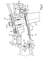
- Um die Leitschaufel 18 variabel einstellen zu können, muss zwischen dem Schaufelblatt 30 und dem Wandungselement 12 ein Spalt 38 vorgesehen sein. Dieser Spalt 38 wird auch als Fahnenspalt bezeichnet und ist besonders gut in
Fig. 2 zu erkennen. Um den Treibstoffverbrauch der Gasturbine zu senken, soll dieser Fahnenspalt 38 während des Betriebs so gut wie möglich verschlossen werden bzw. sein. Andernfalls treten hier starke Drosselverluste durch Überströmung und Induzierung von Verwirbelungen auf. Daher ist das Wandungselement 12 zwischen einer Dichtstellung, in welcher das Wandungselement 12 zumindest an einem Teilbereich einer dem Wandungselement 12 zugewandten Seite 40 des Schaufelblatts 30 der Leitschaufel 18 anliegt, und einer Offenstellung, in welcher das Schaufelblatt 30 und das Wandungselement 12 voneinander beabstandet sind, bewegbar. Die Dichtstellung des Wandungselements 12 ist inFig. 2 mit durchgezogenen Linien dargestellt, die Offenstellung mit gestrichelten Linien. Gut zu erkennen ist, wie das Wandungselement 12 in der Dichtstellung an der Seite 40 des Schaufelblatts 30 anliegt, wodurch der Fahnenspalt 38 im Wesentlichen geschlossen ist. - Das Wandungselement 12 ist zum Bewegen zwischen der Dichtstellung und der Offenstellung mit einem Druck beaufschlagbar. Zu diesem Zweck begrenzen das Wandungselement 12 und ein angrenzendes Gehäuseelement 42 einen Hohlraum 44. Der Hohlraum 44 wird auch als Kavität bezeichnet. Dieser Hohlraum 44 wird über eine als Bohrung 46 ausgebildete Druckzuleitung 48 mit Druck versorgt. Der Druck kann durch Stauluft erzeugt werden, welche bei der Bewegung eines Flugzeugs, Helikopters oder dergleichen entsteht. Alternativ kann für die Druckbeaufschlagung des Hohlraums 44 auch Zapfluft aus einer Kompressorstufe der Gasturbine genutzt werden, wobei die Kompressorstufe auch als Verdichterstufe bezeichnet wird. Dieser Druck im Hohlraum 44 übt eine Stellkraft auf das Wandungselement 12 aus, sodass dieses gegen die Seite 40 des Schaufelblatts 30 bewegt beziehungsweise gedrückt wird. Dies entspricht dem Bewegen des Wandungselements 12 in die Dichtstellung. Es wird mit anderen Worten also eine pneumatische Fahnenspaltschließung an der variablen Leitschaufel 18 realisiert. Die Stau- oder Zapfluft kann vorzugsweise zugleich als Kühlluft zur Kühlung des Turbinengehäuses dienen. Sie kann zumindest teilweise als Leckageströmung durch verbleibende Öffnungen bzw. Spalte zum Heißgas- bzw. Strömungskanal 14 in diesen hinein aus dem Hohlraum 44 austreten, um dadurch zu verhindern, dass Heißgas aus dem Heißgas- bzw. Strömungskanal 14 durch die Öffnungen bzw. Spalte in den Hohlraum 44 eingesogen wird. Da das Wandungselement 12 gemäß der vorliegenden Erfindung zwischen der Dichtstellung und der Offenstellung beweglich ausgebildet ist, die Leitschaufel 18 jedoch, abgesehen von einer möglichen Drehung um ihre Drehachse D2, ortsfest relativ zum restlichen Turbinengehäuse ausgebildet ist, ist eine Spielpassung mit einem kleinen ringförmigen Spalt zwischen dem Wandungselement 12 und der Leitschaufel 18 vorgesehen. Durch den ringförmigen Spalt dieser Spielpassung kann beispielsweise ein Teil der Kühlluft aus dem Hohlraum 44 in die den Heißgas- bzw. Strömungskanal 14 austreten. Bei Bedarf kann jedoch auch ein hier nicht darstelltes Dichtelement an diesem Ringspalt vorgesehen sein, um eine Leckageströmung zumindest weitgehend zu verhindern.
- Weiterhin umfasst das Gehäuse 10 eine Druckableitung 50, mittels welcher ein Druck in dem Hohlraum 44 durch Abblassen von Fluid verringert werden kann. Beispielsweise kann die Druckableitung 50 in die Umgebung führen und damit in dem Hohlraum 44 vorhandene Druckluft abblasen. Bei einem reduzierten Druck in dem Hohlraum 44 wird das Wandungselement 12 durch die Druckdifferenz zwischen dem Druck im Hohlraum 44 und einem Druck im Strömungskanal 14 radial nach außen gedrückt, sodass es in die Offenstellung bewegt wird. Alternativ kann diese Bewegung auch durch ein Federelement bewirkt und/oder unterstützt werden.
- Die Druckableitung 50 umfasst ein schaltbares Ventil 52, mittels welchem der Druck steuerbar oder regelbar ist. Das schaltbare Ventil 52 ist in
Fig. 1 lediglich symbolisch dargestellt. Durch ein Schließen des schaltbaren Ventils 52 kann der Druck in dem Hohlraum 44 erhöht werden, indem Druckluft durch die Druckzuleitung 48 in den Hohlraum 44 strömt und nicht durch die durch das Ventil 52 verschlossene Druckableitung 50 entweichen kann. Sobald der Druck im Hohlraum 44 den Druck im Strömungskanal 14 übersteigt, wird das Wandungselement 12 in die Dichtstellung bewegt. Wenn das schaltbare Ventil 52 geöffnet wird, strömt Druckluft aus dem Hohlraum 44 über die Druckableitung 50 heraus. Sobald der Druck im Hohlraum 44 kleiner geworden ist als der Druck im Strömungskanal 14, wird das Wandungselement 12 damit in die Offenstellung bewegt und gibt den Fahnenspalt 38 frei, sodass die Leitschaufel 18 verstellt werden kann, ohne dass es zur Verschleiß durch Reibung mit dem Wandungselement 12 kommt. Mithilfe des Ventils 52 kann also das Wandungselement 12 während des Betriebs der Gasturbine bedarfsgerecht zwischen der Dichtstellung und der Offenstellung bewegt werden. Vorzugsweise wird dabei der Druck in dem Hohlraum 44 nur kurzzeitig, d.h. weniger als 10 Sekunden, vorzugsweise weniger als 2 Sekunden, weiter bevorzugt weniger als 2 Sekunden, unter den Druck im Strömungskanal 14 gesenkt, nämlich im Wesentlichen nur so lange, wie die Verstellung der Leitschaufel 18 an Zeit benötigt. Hierdurch wird verhindert, dass das Turbinengehäuse während dieser Zeit durch Heißgaseinzug und fehlender Zufuhr von Kühlluft überhitzt. - Dabei ist zu erkennen, dass ein Abblasskanal 54 der Druckableitung 50 einen größeren Querschnitt 56 aufweist als ein Zugangskanal 58 der Druckzuleitung. Der Querschnitt des Zugangskanals 58 ist in
Fig. 2 mit dem Bezugszeichen 60 gekennzeichnet. Der größere Querschnitt 56 des Abblasskanals 54 ermöglicht dabei ein schnelleres Abströmen von Druckluft aus dem Hohlraum 44, als durch den Zugangskanal 58 nachströmen kann. Alternativ oder zusätzlich kann natürlich auch die Druckzuleitung 48 ein schaltbares Ventil umfassen. - Die Druckzuleitung 48 beziehungsweise deren Querschnitt 60 ist vorzugsweise so groß gewählt, dass sich zwischen dem Zuströmen von Druckluft in den Hohlraum 44 und einem Abströmen durch Leckagen im Gehäuse 10 ein Gleichgewicht einstellt. Das heißt, es strömt bei einem geschlossenen Ventil 52 gerade soviel Druckluft nach, das im Hohlraum 44 ein im Wesentlichen konstanter Druck gewährleistet wird, welcher das Wandungselement 12 in der Dichtstellung hält. Daher sollte die Zufuhr des unter Druck stehenden Fluids derart gewählt sein, dass nicht so viel Druck durch Leckagen aus dem Hohlraum 44 entweicht, dass sich das Wandungselement 12 ungewollt in die Offenstellung bewegt. Ebenso sollte es nicht zu einer unzulässigen Erhöhung des Drucks im Hohlraum 44 kommen. Hierzu kann ein Überdruckventil bzw. eine entsprechende Überdruckbegrenzung durch das Ventil 52 vorgesehen sein.
- Weiterhin zu erkennen ist, dass das Wandungselement 12 eine einseitige Lagerung 62 am Gehäuseelement 42 aufweist. Hierfür ist ein Nasenelement 64 des Wandungselements 12 in eine Nut 66 des Gehäuseelements 42 eingeschoben. In der Offenstellung wird das Wandungselement 12 an seiner der Lagerung 62 abgewandten Seite 68 in Bezug auf den Strömungskanal 14 radial nach außen verschwenkt bzw. gebogen. In der Dichtstellung wird das Wandungselement 12 im Gegensatz dazu an der Seite 68 radial in Richtung des Strömungskanals 14 verschwenkt bzw. gebogen. Alternativ kann das Wandungselement 12 auch drehbar an einem Gelenk an der Lagerung 62 gehalten sein.
- Weiterhin zu erkennen ist, dass das Wandungselement 12 an der der Lagerung 62 abgewandten Seite 68 die größte Relativbewegung zu dem Gehäuseelement 42 bei einer Bewegung zwischen der Dichtstellung und der Offenstellung durchführt. Dabei wird ein Spalt zwischen dem Wandungselement 12 und dem Gehäuseelement 42 freigegeben. Um hier unnötige Druckverluste im Strömungskanal 14 zu vermeiden, welche zu einem erhöhten Treibstoffverbrauch führen könnten, und um den Einzug größerer Mengen von Heißgas in den Hohlraum 44 zu vermeiden, ist an dieser Stelle ein Dichtungselement 70 angeordnet. Bei der Bewegung des Wandungselements 12 gleitet dieses an dem Dichtungselement 70 entlang.
- In
Fig. 2 ist ebenfalls zu erkennen, dass das Wandungselement 12 eine Öffnung 72 umfasst, in welcher ein Schaufelteller 74 der Leitschaufel 18 angeordnet ist. Wie zuvor bereits erwähnt, ist zwischen dem Schaufelteller 74 und der Öffnung 72 eine Spielpassung, beispielsweise in Form eines kleinen ringförmigen Spalts, vorgesehen, welche ein Drehen der Leitschaufel 18 um die Drehachse D2 ermöglicht und Druckverluste im Strömungskanal 14 weitgehend reduziert. - Man erkennt, dass eine den Strömungskanal 14 begrenzende Fläche 76 des Wandungselements 12 und der Schaufelteller 74 in der Dichtstellung bündig aneinander anschließen. Das heißt, das Wandungselement 12 und der Schaufelteller 74 begrenzen den Strömungskanal 14 in radial äußerer Richtung mit einer aerodynamisch gleichförmigen Fläche, sodass ein Induzieren von Wirbeln oder anderer unerwünschter aerodynamischer Erscheinungen in der Gasströmung im Strömungskanal 14 vermieden wird.
- Durch das in die Dichtstellung bewegte Wandungselement 12 ist die Leitschaufel 18 reibschlüssig an dieser festgelegt. Damit ist die Leitschaufel 18 verdrehsicher am Wandungselement 12 gehalten, sodass auf zusätzliche Elemente zum Festlegen der Leitschaufel 18 vorteilhaft verzichtet werden kann.
- Weiterhin ist zu erkennen, dass an dem Gehäuse 10 ein Anschlagelement 78 zur Begrenzung der Bewegung des Wandungselements 12 in die Offenstellung sowie ein Anschlagelement 80 zur Begrenzung der Bewegung des Wandungselements 12 in die Dichtstellung vorgesehen ist. Das Anschlagelement 78 des Gehäuses 10 ist dabei als ein Nasenelement ausgebildet. Ein korrespondierendes Nasenelement 82 des Wandungselements 12 liegt in Offenstellung an dem Anschlagelement 78 an. Damit wird besonders zuverlässig verhindert, dass das Wandungselement 12 durch einen zu hohen Druckunterschied zwischen dem Strömungskanal 14 und dem Hohlraum 44 in der Offenstellung zu weit radial nach außen gebogen wird und dadurch entweder selbst beschädigt wird oder das Gehäuseelement 42 beschädigt. Das Anschlagelement 80 ist als Kante in dem Gehäuseelement 42 ausgebildet, auf welchem ein korrespondierendes Nasenelement 84 des Wandungselements 12 in Dichtstellung zur Anlage kommen kann. Hierdurch wird verhindert, dass sich das Wandungselement 12 unzulässig weit radial nach innen bewegt oder verbiegt. Zudem wird auch das Schaufelblatt 30 vor Beschädigungen durch eine übermäßige Bewegung des Wandungselements 12 geschützt.
- Die gezeigte Gasturbine beziehungsweise das gezeigte Flugtriebwerk wird wie folgt betrieben: Sobald ein Betriebszustand vorliegt, welcher ein Verstellen der Leitschaufel 18 erfordert, wird das Wandungselement 12 aus der Dichtstellung in die Offenstellung bewegt. Zu diesem Zweck wird das schaltbare Ventil 52 geöffnet und Druckluft strömt über die Druckableitung 50 aus dem Hohlraum 44 heraus. Damit reduziert sich der auf das Wandungselement 12 wirkende Druck in dem Hohlraum 44. Aufgrund des herrschenden Drucks in dem Strömungskanal 14 wird das Wandungselement 12 in die Offenstellung bewegt beziehungsweise verbogen und gibt damit den Fahnenspalt 38 frei. Somit kann die Leitschaufel 18 mittels der Einstelleinrichtung um die Drehachse D2 gedreht werden, bis eine optimale Anströmung der Turbinenschaufel 20 für den betreffenden Betriebspunkt eingestellt ist. Sobald die Leitschaufel 18 in die richtige Position verstellt beziehungsweise verdreht wurde, wird das schaltbare Ventil 52 wieder verschlossen. Durch die Druckzuleitung 48 in den Hohlraum 44 strömende Druckluft übt einen Druck auf das Wandungselement 12 aus, welcher radial von außen aus dem Hohlraum 44 auf das Wandungselement 12 wirkt. Entsprechend wird das Wandungselement 12 wieder in die Dichtstellung zurückbewegt bzw. -gebogen und der Fahnenspalt 38 zumindest größtenteils geschlossen. Durch den Fahnenspalt 38 und gegebenenfalls andere Spalte während der Verstellbewegung des Wandungselements 12 und der Leitschaufeln 18 treten damit nur kurzzeitige Verluste auf, welche für den Treibstoffverbrauch über die gesamte Flugdauer des Flugzeugs, Helikopters oder dergleichen vernachlässigbar sind. Dagegen werden während des restlichen Betriebs der Gasturbine beziehungsweise des Flugtriebwerks äußere Verluste im Strömungskanal 14 nahezu vollständig vermieden, was einen deutlichen Wirkungsgradgewinn zur Folge hat.
- Es sei noch angemerkt, dass das Wandungselement 12 gegenüber ihm in Umfangsrichtung benachbarten weiteren Wandungselementen, die identisch zu dem Wandungselement 12 ausgebildet sein können, zum Beispiel mittels nicht dargestellter Dichtbleche, die in entsprechenden Dichtnuten des Wandungselements 12 vorgesehen sind abgedichtet sein kann, wie dies aus dem Stand der Technik hinlänglich bekannt ist. Hierdurch kann ein hoher Grad an Dichtigkeit zwischen den in Umfangsrichtung benachbarten Wandungselementen sowohl in der Dichtstellung als auch in der Offenstellung und beim Übergang zwischen diesen Stellungen erzielt werden. Vorzugsweise werde alle Verstellleitschaufeln zeitgleich verstellt, so dass auch alle ihnen zugeordneten Wandungselemente 12 zeitgleich von der Dichtstellung in die Offenstellung und zurück überführt werden.
-
- 10
- Gehäuse
- 12
- Wandungselement
- 14
- Strömungskanal
- 16
- Rotor
- 18
- Leitschaufel
- 20
- Turbinenschaufel
- 22
- Dichtungselement
- 24
- Schaft
- 26
- Wälzlagerung
- 28
- Schaftelement
- 30
- Schaufelblatt
- 32
- Pfeile
- 36
- Hebel
- 38
- Spalt
- 40
- Seite
- 42
- Gehäuseelement
- 44
- Hohlraum
- 46
- Bohrung
- 48
- Druckzuleitung
- 50
- Druckableitung
- 52
- Ventil
- 54
- Abblasskanal
- 56
- größerer Querschnitt
- 58
- Zugangskanal
- 60
- kleinerer Querschnitt
- 62
- Lagerung
- 64
- Nasenelement
- 66
- Nut
- 68
- Seite
- 70
- Dichtungselement
- 72
- Öffnung
- 74
- Schaufelteller
- 76
- Fläche
- 78
- Anschlagelement
- 80
- Anschlagelement
- 82
- Nasenelement
- 84
- Nasenelement
- D
- Drehachse Rotor
- D2
- Drehachse Leitschaufel
Claims (15)
- Gehäuse (10) für eine Gasturbine, an welchem wenigstens ein Wandungselement (12) beweglich gelagert ist, das einen Strömungskanal (14) des Gehäuses (10) in radialer Richtung einer Drehachse (D) eines Rotors (16) der Gasturbine nach außen hin begrenzt, wobei das Gehäuse (10) wenigstens eine variabel einstellbare Leitschaufel (18) umfasst, die sich durch das Wandungselement (12) in den Strömungskanal (14) erstreckt,
dadurch gekennzeichnet, dass
das Wandungselement (12) zwischen einer Dichtstellung, in welcher das Wandungselement (12) zumindest an einem Teilbereich einer dem Wandungselement zugewandten Seite (40) eines Schaufelblatts (30) der Leitschaufel (18) anliegt, und einer Offenstellung, in welcher das Schaufelblatt (30) und das Wandungselement (12) voneinander beabstandet sind, bewegbar ist. - Gehäuse (10) nach Anspruch 1,
dadurch gekennzeichnet, dass
das Wandungselement (12) zum Bewegen zwischen der Offenstellung und der Dichtstellung mit einem unter Druck stehenden Fluid beaufschlagbar ist. - Gehäuse (10) nach Anspruch 2,
dadurch gekennzeichnet, dass
dieses eine Druckzuleitung (48) zum Zuführen des unter Druck stehenden Fluids und eine Druckableitung (50) zum Abführen des unter Druck stehenden Fluids umfasst. - Gehäuse (10) nach einem Anspruch 3,
dadurch gekennzeichnet, dass
die Druckzuleitung (48) und/oder die Druckableitung (50) ein Ventil (52) umfasst, mittels welchem der Druck auf das Wandungselement (12) steuerbar und/oder regelbar ist. - Gehäuse (10) nach Anspruch 3 oder 4,
dadurch gekennzeichnet, dass
ein Abblasskanal (54) der Druckableitung (50) einen größeren Querschnitt (56) aufweist als ein Zuführkanal (58) der Druckzuleitung (48). - Gehäuse (10) nach einem Anspruch 1 bis 5,
dadurch gekennzeichnet, dass
das Wandungselement (12) über eine Lagerung (62) einseitig an einem Gehäuseelement (42) gehalten ist. - Gehäuse (10) nach einem Anspruch 1 bis 6,
dadurch gekennzeichnet, dass
zwischen dem Wandungselement (12) und einem angrenzenden Gehäuseelement (42) wenigstens ein Dichtungselement (70) angeordnet ist. - Gehäuse (10) nach einem Anspruch 6 und 7
dadurch gekennzeichnet, dass
das Dichtungselement (70) an einer der Lagerung (62) gegenüberliegenden Seite (68) des Wandungselements (12) angeordnet ist. - Gehäuse (10) nach einem Anspruch 1 bis 8,
dadurch gekennzeichnet, dass
eine den Strömungskanal (14) begrenzende Fläche (76) des Wandungselements (12) und ein Schaufelteller (74) der Leitschaufel (18) in der Dichtstellung zumindest im Wesentlichen bündig aneinander anschließen. - Gehäuse (10) nach einem Anspruch 1 bis 9,
dadurch gekennzeichnet, dass
das Wandungselement (12) eine Öffnung (72) umfasst, in welcher ein Schaufelteller (74) der Leitschaufel (18) angeordnet ist. - Gehäuse (10) nach Anspruch 1 bis 10,
dadurch gekennzeichnet, dass
das Wandungselement (12) und die Leitschaufel (18) in der Dichtstellung reibschlüssig aneinander festgelegt sind. - Gehäuse (10) nach Anspruch 1 bis 11,
dadurch gekennzeichnet, dass
dieses wenigstens ein Anschlagelement (78, 80) umfasst, welches die Bewegung des Wandungselements (12) in die Dichtstellung und/oder in die Offenstellung begrenzt. - Gasturbine, insbesondere Flugtriebwerk, mit einem Gehäuse (10) nach einem der Ansprüche 1 bis 12.
- Verfahren zum Betreiben einer Gasturbine mit einem Gehäuse (10) nach einem der Ansprüche 1 bis 12, bei welchem das Wandungselement (12) zwischen der Dichtstellung und der Offenstellung bewegt wird.
- Verfahren nach Anspruch 14,
durch folgende Schritte gekennzeichnet:- Bewegen des Wandungselements (12) in die Offenstellung;- Verstellen der Leitschaufel (18); und- Bewegen des Wandungselements (12) in die Schließstellung.
Applications Claiming Priority (1)
| Application Number | Priority Date | Filing Date | Title |
|---|---|---|---|
| DE102014214915.0A DE102014214915B3 (de) | 2014-07-30 | 2014-07-30 | Gehäuse für eine Gasturbine, Flugtriebwerk sowie ein Verfahren zum Betreiben einer Gasturbine |
Publications (2)
| Publication Number | Publication Date |
|---|---|
| EP2980366A1 true EP2980366A1 (de) | 2016-02-03 |
| EP2980366B1 EP2980366B1 (de) | 2020-04-08 |
Family
ID=53835875
Family Applications (1)
| Application Number | Title | Priority Date | Filing Date |
|---|---|---|---|
| EP15176353.9A Active EP2980366B1 (de) | 2014-07-30 | 2015-07-10 | Gehäuse für eine gasturbine, flugtriebwerk sowie ein verfahren zum betreiben einer gasturbine |
Country Status (4)
| Country | Link |
|---|---|
| US (1) | US9988927B2 (de) |
| EP (1) | EP2980366B1 (de) |
| DE (1) | DE102014214915B3 (de) |
| ES (1) | ES2790578T3 (de) |
Cited By (1)
| Publication number | Priority date | Publication date | Assignee | Title |
|---|---|---|---|---|
| CN109209525A (zh) * | 2018-11-23 | 2019-01-15 | 陈济颖 | 一种高背压蒸汽轮机组 |
Families Citing this family (5)
| Publication number | Priority date | Publication date | Assignee | Title |
|---|---|---|---|---|
| EP2960438B1 (de) * | 2014-06-26 | 2020-09-02 | MTU Aero Engines GmbH | Leitschaufelvorrichtung für eine gasturbine sowie gasturbine mit einer solchen leitschaufelvorrichtung |
| GB2552048A (en) * | 2016-03-22 | 2018-01-10 | Gen Electric | Method, system, and apparatus for reducing a turbine clearance |
| DE102016110269A1 (de) * | 2016-06-03 | 2017-12-07 | Man Diesel & Turbo Se | Axialturbine eines Turboladers und Turbolader |
| CN109751089B (zh) * | 2017-11-03 | 2023-09-19 | 长兴永能动力科技有限公司 | 一种向心式汽轮机可调喷嘴 |
| DE102022128618A1 (de) * | 2022-10-28 | 2024-05-08 | Atlas Copco Energas Gmbh | Turbomaschinen und Verfahren zum Betrieb einer Turbomaschine |
Citations (4)
| Publication number | Priority date | Publication date | Assignee | Title |
|---|---|---|---|---|
| US2919809A (en) | 1958-12-19 | 1960-01-05 | Cal Dak Company Inc | Rack |
| US5873700A (en) * | 1996-01-26 | 1999-02-23 | Hitachi, Ltd. | Hydraulic machine |
| WO2007045874A1 (en) * | 2005-10-20 | 2007-04-26 | Cummins Turbo Technologies Limited | Turbine with variable inlet nozzle geometry |
| EP2407673A1 (de) * | 2010-07-12 | 2012-01-18 | Siemens Aktiengesellschaft | Verdichter |
Family Cites Families (5)
| Publication number | Priority date | Publication date | Assignee | Title |
|---|---|---|---|---|
| US2919890A (en) * | 1955-09-16 | 1960-01-05 | Gen Electric | Adjustable gas turbine nozzle assembly |
| DE2931766C2 (de) | 1979-08-04 | 1982-08-05 | MTU Motoren- und Turbinen-Union München GmbH, 8000 München | Dichtungseinrichtung für die freien Schaufelenden eines Verstell-Leitapparates einer Gasturbine |
| DE19961613A1 (de) * | 1999-12-21 | 2001-07-19 | Daimler Chrysler Ag | Abgasturbine eines Abgasturboladers für eine Brennkraftmaschine |
| US9133726B2 (en) * | 2007-09-17 | 2015-09-15 | United Technologies Corporation | Seal for gas turbine engine component |
| FR2938293B1 (fr) * | 2008-11-12 | 2015-08-21 | Snecma | Dispositif de regulation du debit d'air alimentant une cavite de ventillation de turbine d'une section de turbine de turbomachine |
-
2014
- 2014-07-30 DE DE102014214915.0A patent/DE102014214915B3/de not_active Expired - Fee Related
-
2015
- 2015-07-10 EP EP15176353.9A patent/EP2980366B1/de active Active
- 2015-07-10 ES ES15176353T patent/ES2790578T3/es active Active
- 2015-07-29 US US14/812,204 patent/US9988927B2/en active Active
Patent Citations (4)
| Publication number | Priority date | Publication date | Assignee | Title |
|---|---|---|---|---|
| US2919809A (en) | 1958-12-19 | 1960-01-05 | Cal Dak Company Inc | Rack |
| US5873700A (en) * | 1996-01-26 | 1999-02-23 | Hitachi, Ltd. | Hydraulic machine |
| WO2007045874A1 (en) * | 2005-10-20 | 2007-04-26 | Cummins Turbo Technologies Limited | Turbine with variable inlet nozzle geometry |
| EP2407673A1 (de) * | 2010-07-12 | 2012-01-18 | Siemens Aktiengesellschaft | Verdichter |
Cited By (1)
| Publication number | Priority date | Publication date | Assignee | Title |
|---|---|---|---|---|
| CN109209525A (zh) * | 2018-11-23 | 2019-01-15 | 陈济颖 | 一种高背压蒸汽轮机组 |
Also Published As
| Publication number | Publication date |
|---|---|
| EP2980366B1 (de) | 2020-04-08 |
| US20160032760A1 (en) | 2016-02-04 |
| ES2790578T3 (es) | 2020-10-28 |
| US9988927B2 (en) | 2018-06-05 |
| DE102014214915B3 (de) | 2015-12-10 |
Similar Documents
| Publication | Publication Date | Title |
|---|---|---|
| EP2980366B1 (de) | Gehäuse für eine gasturbine, flugtriebwerk sowie ein verfahren zum betreiben einer gasturbine | |
| DE102011054468B4 (de) | Variables Turbinenleitapparatsystem | |
| EP3388649B1 (de) | Triebwerksgondel für ein turbofan-triebwerk | |
| EP3306066B1 (de) | Turbofan-triebwerk für ein ziviles überschallflugzeug | |
| EP2835522B2 (de) | Vorrichtung und Verfahren zum Abblasen von Verdichterluft in einem Triebwerk | |
| EP2955335B1 (de) | Leitschaufelkranz, leitschaufel, innenring und strömungsmaschine | |
| DE2042478A1 (de) | Gasturbinenstrahltriebwerk für Flugzeuge mit Einrichtungen zur Bauteilkühlung und Verdichterregelung | |
| DE102011053712A1 (de) | Windturbinenrotorblatt mit betätigbaren profilpassagen | |
| DE4003802A1 (de) | Spaltregulierung für die Turbine eines Gasturbinentriebwerks | |
| DE102008028987A1 (de) | Turboproptriebwerk mit einer Vorrichtung zum Erzeugen eines Kühlluftstroms | |
| EP2596213B1 (de) | Dampfturbine mit einer internen kühlung | |
| DE4214775A1 (de) | Dampfturbine mit einem Drehschieber | |
| EP2980365A1 (de) | Leitschaufel für eine gastrubine mit stirnseitigen dichtelementen | |
| EP2617947B1 (de) | Fluggasturbine mit justierbarem Fan | |
| DE602005005903T2 (de) | Zusammenbau einer Nasenhaube einer Turbomaschine und einer Fanschaufel-Welle. | |
| DE102011103518A1 (de) | Abblaseventil | |
| DE102013002192A1 (de) | Turbine für einen Abgasturbolader | |
| DE2629049A1 (de) | Duese mit variablem querschnitt und belastungsausgleich | |
| EP2146056A2 (de) | Gasturbinentriebwerk mit verstellbaren Leitschaufeln | |
| DE1274412B (de) | Verriegelungsvorrichtung | |
| WO2014012725A1 (de) | Paralleldiffusor für eine fluidmaschine | |
| DE102019000252A1 (de) | Axialschieber-Turbine mit axial verschiebbarem Leitgitterträger | |
| WO2013072294A2 (de) | Abgasturbolader mit einer variablen turbinengeometrie und einer tellerfeder zur abdichtung | |
| WO2017097665A1 (de) | Fluggasturbine mit variabler austrittsdüse eines nebenstromkanals | |
| EP1541803A2 (de) | Anordnung zur Lagerentlastung in einer Gasturbine |
Legal Events
| Date | Code | Title | Description |
|---|---|---|---|
| PUAI | Public reference made under article 153(3) epc to a published international application that has entered the european phase |
Free format text: ORIGINAL CODE: 0009012 |
|
| AK | Designated contracting states |
Kind code of ref document: A1 Designated state(s): AL AT BE BG CH CY CZ DE DK EE ES FI FR GB GR HR HU IE IS IT LI LT LU LV MC MK MT NL NO PL PT RO RS SE SI SK SM TR |
|
| AX | Request for extension of the european patent |
Extension state: BA ME |
|
| 17P | Request for examination filed |
Effective date: 20160727 |
|
| RBV | Designated contracting states (corrected) |
Designated state(s): AL AT BE BG CH CY CZ DE DK EE ES FI FR GB GR HR HU IE IS IT LI LT LU LV MC MK MT NL NO PL PT RO RS SE SI SK SM TR |
|
| RIC1 | Information provided on ipc code assigned before grant |
Ipc: F04D 29/56 20060101ALI20190924BHEP Ipc: F01D 17/16 20060101AFI20190924BHEP Ipc: F01D 9/04 20060101ALI20190924BHEP |
|
| GRAP | Despatch of communication of intention to grant a patent |
Free format text: ORIGINAL CODE: EPIDOSNIGR1 |
|
| STAA | Information on the status of an ep patent application or granted ep patent |
Free format text: STATUS: GRANT OF PATENT IS INTENDED |
|
| INTG | Intention to grant announced |
Effective date: 20191105 |
|
| GRAS | Grant fee paid |
Free format text: ORIGINAL CODE: EPIDOSNIGR3 |
|
| GRAA | (expected) grant |
Free format text: ORIGINAL CODE: 0009210 |
|
| STAA | Information on the status of an ep patent application or granted ep patent |
Free format text: STATUS: THE PATENT HAS BEEN GRANTED |
|
| AK | Designated contracting states |
Kind code of ref document: B1 Designated state(s): AL AT BE BG CH CY CZ DE DK EE ES FI FR GB GR HR HU IE IS IT LI LT LU LV MC MK MT NL NO PL PT RO RS SE SI SK SM TR |
|
| REG | Reference to a national code |
Ref country code: AT Ref legal event code: REF Ref document number: 1254659 Country of ref document: AT Kind code of ref document: T Effective date: 20200415 Ref country code: CH Ref legal event code: EP |
|
| REG | Reference to a national code |
Ref country code: IE Ref legal event code: FG4D Free format text: LANGUAGE OF EP DOCUMENT: GERMAN |
|
| REG | Reference to a national code |
Ref country code: DE Ref legal event code: R096 Ref document number: 502015012200 Country of ref document: DE |
|
| REG | Reference to a national code |
Ref country code: NL Ref legal event code: MP Effective date: 20200408 |
|
| REG | Reference to a national code |
Ref country code: LT Ref legal event code: MG4D |
|
| REG | Reference to a national code |
Ref country code: ES Ref legal event code: FG2A Ref document number: 2790578 Country of ref document: ES Kind code of ref document: T3 Effective date: 20201028 |
|
| PG25 | Lapsed in a contracting state [announced via postgrant information from national office to epo] |
Ref country code: FI Free format text: LAPSE BECAUSE OF FAILURE TO SUBMIT A TRANSLATION OF THE DESCRIPTION OR TO PAY THE FEE WITHIN THE PRESCRIBED TIME-LIMIT Effective date: 20200408 Ref country code: SE Free format text: LAPSE BECAUSE OF FAILURE TO SUBMIT A TRANSLATION OF THE DESCRIPTION OR TO PAY THE FEE WITHIN THE PRESCRIBED TIME-LIMIT Effective date: 20200408 Ref country code: LT Free format text: LAPSE BECAUSE OF FAILURE TO SUBMIT A TRANSLATION OF THE DESCRIPTION OR TO PAY THE FEE WITHIN THE PRESCRIBED TIME-LIMIT Effective date: 20200408 Ref country code: NL Free format text: LAPSE BECAUSE OF FAILURE TO SUBMIT A TRANSLATION OF THE DESCRIPTION OR TO PAY THE FEE WITHIN THE PRESCRIBED TIME-LIMIT Effective date: 20200408 Ref country code: GR Free format text: LAPSE BECAUSE OF FAILURE TO SUBMIT A TRANSLATION OF THE DESCRIPTION OR TO PAY THE FEE WITHIN THE PRESCRIBED TIME-LIMIT Effective date: 20200709 Ref country code: NO Free format text: LAPSE BECAUSE OF FAILURE TO SUBMIT A TRANSLATION OF THE DESCRIPTION OR TO PAY THE FEE WITHIN THE PRESCRIBED TIME-LIMIT Effective date: 20200708 Ref country code: IS Free format text: LAPSE BECAUSE OF FAILURE TO SUBMIT A TRANSLATION OF THE DESCRIPTION OR TO PAY THE FEE WITHIN THE PRESCRIBED TIME-LIMIT Effective date: 20200808 Ref country code: PT Free format text: LAPSE BECAUSE OF FAILURE TO SUBMIT A TRANSLATION OF THE DESCRIPTION OR TO PAY THE FEE WITHIN THE PRESCRIBED TIME-LIMIT Effective date: 20200817 |
|
| PG25 | Lapsed in a contracting state [announced via postgrant information from national office to epo] |
Ref country code: RS Free format text: LAPSE BECAUSE OF FAILURE TO SUBMIT A TRANSLATION OF THE DESCRIPTION OR TO PAY THE FEE WITHIN THE PRESCRIBED TIME-LIMIT Effective date: 20200408 Ref country code: BG Free format text: LAPSE BECAUSE OF FAILURE TO SUBMIT A TRANSLATION OF THE DESCRIPTION OR TO PAY THE FEE WITHIN THE PRESCRIBED TIME-LIMIT Effective date: 20200708 Ref country code: LV Free format text: LAPSE BECAUSE OF FAILURE TO SUBMIT A TRANSLATION OF THE DESCRIPTION OR TO PAY THE FEE WITHIN THE PRESCRIBED TIME-LIMIT Effective date: 20200408 Ref country code: HR Free format text: LAPSE BECAUSE OF FAILURE TO SUBMIT A TRANSLATION OF THE DESCRIPTION OR TO PAY THE FEE WITHIN THE PRESCRIBED TIME-LIMIT Effective date: 20200408 |
|
| PG25 | Lapsed in a contracting state [announced via postgrant information from national office to epo] |
Ref country code: AL Free format text: LAPSE BECAUSE OF FAILURE TO SUBMIT A TRANSLATION OF THE DESCRIPTION OR TO PAY THE FEE WITHIN THE PRESCRIBED TIME-LIMIT Effective date: 20200408 |
|
| REG | Reference to a national code |
Ref country code: DE Ref legal event code: R097 Ref document number: 502015012200 Country of ref document: DE |
|
| PG25 | Lapsed in a contracting state [announced via postgrant information from national office to epo] |
Ref country code: DK Free format text: LAPSE BECAUSE OF FAILURE TO SUBMIT A TRANSLATION OF THE DESCRIPTION OR TO PAY THE FEE WITHIN THE PRESCRIBED TIME-LIMIT Effective date: 20200408 Ref country code: EE Free format text: LAPSE BECAUSE OF FAILURE TO SUBMIT A TRANSLATION OF THE DESCRIPTION OR TO PAY THE FEE WITHIN THE PRESCRIBED TIME-LIMIT Effective date: 20200408 Ref country code: SM Free format text: LAPSE BECAUSE OF FAILURE TO SUBMIT A TRANSLATION OF THE DESCRIPTION OR TO PAY THE FEE WITHIN THE PRESCRIBED TIME-LIMIT Effective date: 20200408 Ref country code: RO Free format text: LAPSE BECAUSE OF FAILURE TO SUBMIT A TRANSLATION OF THE DESCRIPTION OR TO PAY THE FEE WITHIN THE PRESCRIBED TIME-LIMIT Effective date: 20200408 Ref country code: IT Free format text: LAPSE BECAUSE OF FAILURE TO SUBMIT A TRANSLATION OF THE DESCRIPTION OR TO PAY THE FEE WITHIN THE PRESCRIBED TIME-LIMIT Effective date: 20200408 Ref country code: CZ Free format text: LAPSE BECAUSE OF FAILURE TO SUBMIT A TRANSLATION OF THE DESCRIPTION OR TO PAY THE FEE WITHIN THE PRESCRIBED TIME-LIMIT Effective date: 20200408 |
|
| PLBE | No opposition filed within time limit |
Free format text: ORIGINAL CODE: 0009261 |
|
| STAA | Information on the status of an ep patent application or granted ep patent |
Free format text: STATUS: NO OPPOSITION FILED WITHIN TIME LIMIT |
|
| PG25 | Lapsed in a contracting state [announced via postgrant information from national office to epo] |
Ref country code: PL Free format text: LAPSE BECAUSE OF FAILURE TO SUBMIT A TRANSLATION OF THE DESCRIPTION OR TO PAY THE FEE WITHIN THE PRESCRIBED TIME-LIMIT Effective date: 20200408 Ref country code: SK Free format text: LAPSE BECAUSE OF FAILURE TO SUBMIT A TRANSLATION OF THE DESCRIPTION OR TO PAY THE FEE WITHIN THE PRESCRIBED TIME-LIMIT Effective date: 20200408 Ref country code: MC Free format text: LAPSE BECAUSE OF FAILURE TO SUBMIT A TRANSLATION OF THE DESCRIPTION OR TO PAY THE FEE WITHIN THE PRESCRIBED TIME-LIMIT Effective date: 20200408 |
|
| REG | Reference to a national code |
Ref country code: CH Ref legal event code: PL |
|
| 26N | No opposition filed |
Effective date: 20210112 |
|
| REG | Reference to a national code |
Ref country code: BE Ref legal event code: MM Effective date: 20200731 |
|
| PG25 | Lapsed in a contracting state [announced via postgrant information from national office to epo] |
Ref country code: CH Free format text: LAPSE BECAUSE OF NON-PAYMENT OF DUE FEES Effective date: 20200731 Ref country code: LU Free format text: LAPSE BECAUSE OF NON-PAYMENT OF DUE FEES Effective date: 20200710 Ref country code: LI Free format text: LAPSE BECAUSE OF NON-PAYMENT OF DUE FEES Effective date: 20200731 |
|
| PG25 | Lapsed in a contracting state [announced via postgrant information from national office to epo] |
Ref country code: BE Free format text: LAPSE BECAUSE OF NON-PAYMENT OF DUE FEES Effective date: 20200731 Ref country code: SI Free format text: LAPSE BECAUSE OF FAILURE TO SUBMIT A TRANSLATION OF THE DESCRIPTION OR TO PAY THE FEE WITHIN THE PRESCRIBED TIME-LIMIT Effective date: 20200408 |
|
| PG25 | Lapsed in a contracting state [announced via postgrant information from national office to epo] |
Ref country code: IE Free format text: LAPSE BECAUSE OF NON-PAYMENT OF DUE FEES Effective date: 20200710 |
|
| REG | Reference to a national code |
Ref country code: AT Ref legal event code: MM01 Ref document number: 1254659 Country of ref document: AT Kind code of ref document: T Effective date: 20200710 |
|
| PG25 | Lapsed in a contracting state [announced via postgrant information from national office to epo] |
Ref country code: AT Free format text: LAPSE BECAUSE OF NON-PAYMENT OF DUE FEES Effective date: 20200710 |
|
| PG25 | Lapsed in a contracting state [announced via postgrant information from national office to epo] |
Ref country code: TR Free format text: LAPSE BECAUSE OF FAILURE TO SUBMIT A TRANSLATION OF THE DESCRIPTION OR TO PAY THE FEE WITHIN THE PRESCRIBED TIME-LIMIT Effective date: 20200408 Ref country code: MT Free format text: LAPSE BECAUSE OF FAILURE TO SUBMIT A TRANSLATION OF THE DESCRIPTION OR TO PAY THE FEE WITHIN THE PRESCRIBED TIME-LIMIT Effective date: 20200408 Ref country code: CY Free format text: LAPSE BECAUSE OF FAILURE TO SUBMIT A TRANSLATION OF THE DESCRIPTION OR TO PAY THE FEE WITHIN THE PRESCRIBED TIME-LIMIT Effective date: 20200408 |
|
| PG25 | Lapsed in a contracting state [announced via postgrant information from national office to epo] |
Ref country code: MK Free format text: LAPSE BECAUSE OF FAILURE TO SUBMIT A TRANSLATION OF THE DESCRIPTION OR TO PAY THE FEE WITHIN THE PRESCRIBED TIME-LIMIT Effective date: 20200408 |
|
| PGFP | Annual fee paid to national office [announced via postgrant information from national office to epo] |
Ref country code: GB Payment date: 20220725 Year of fee payment: 8 Ref country code: ES Payment date: 20220819 Year of fee payment: 8 Ref country code: DE Payment date: 20220621 Year of fee payment: 8 |
|
| PGFP | Annual fee paid to national office [announced via postgrant information from national office to epo] |
Ref country code: FR Payment date: 20220727 Year of fee payment: 8 |
|
| REG | Reference to a national code |
Ref country code: DE Ref legal event code: R119 Ref document number: 502015012200 Country of ref document: DE |
|
| GBPC | Gb: european patent ceased through non-payment of renewal fee |
Effective date: 20230710 |
|
| PG25 | Lapsed in a contracting state [announced via postgrant information from national office to epo] |
Ref country code: DE Free format text: LAPSE BECAUSE OF NON-PAYMENT OF DUE FEES Effective date: 20240201 Ref country code: GB Free format text: LAPSE BECAUSE OF NON-PAYMENT OF DUE FEES Effective date: 20230710 |
|
| PG25 | Lapsed in a contracting state [announced via postgrant information from national office to epo] |
Ref country code: FR Free format text: LAPSE BECAUSE OF NON-PAYMENT OF DUE FEES Effective date: 20230731 |
|
| REG | Reference to a national code |
Ref country code: ES Ref legal event code: FD2A Effective date: 20240828 |
|
| PG25 | Lapsed in a contracting state [announced via postgrant information from national office to epo] |
Ref country code: ES Free format text: LAPSE BECAUSE OF NON-PAYMENT OF DUE FEES Effective date: 20230711 |
|
| PG25 | Lapsed in a contracting state [announced via postgrant information from national office to epo] |
Ref country code: ES Free format text: LAPSE BECAUSE OF NON-PAYMENT OF DUE FEES Effective date: 20230711 |