EP2980366A1 - Boitier pour une turbine a gaz, groupe motopropulseur et procede de fonctionnement d'une turbine a gaz - Google Patents
Boitier pour une turbine a gaz, groupe motopropulseur et procede de fonctionnement d'une turbine a gaz Download PDFInfo
- Publication number
- EP2980366A1 EP2980366A1 EP15176353.9A EP15176353A EP2980366A1 EP 2980366 A1 EP2980366 A1 EP 2980366A1 EP 15176353 A EP15176353 A EP 15176353A EP 2980366 A1 EP2980366 A1 EP 2980366A1
- Authority
- EP
- European Patent Office
- Prior art keywords
- housing
- wall element
- gas turbine
- pressure
- open position
- Prior art date
- Legal status (The legal status is an assumption and is not a legal conclusion. Google has not performed a legal analysis and makes no representation as to the accuracy of the status listed.)
- Granted
Links
- 238000000034 method Methods 0.000 title claims abstract description 9
- 238000007789 sealing Methods 0.000 claims abstract description 61
- 239000012530 fluid Substances 0.000 claims description 14
- 238000007599 discharging Methods 0.000 claims description 3
- 230000001105 regulatory effect Effects 0.000 claims description 3
- 239000000446 fuel Substances 0.000 description 9
- 238000001816 cooling Methods 0.000 description 4
- 230000007704 transition Effects 0.000 description 3
- 230000006978 adaptation Effects 0.000 description 2
- 230000033228 biological regulation Effects 0.000 description 2
- 238000002485 combustion reaction Methods 0.000 description 2
- 239000011796 hollow space material Substances 0.000 description 2
- 238000012423 maintenance Methods 0.000 description 2
- 230000002441 reversible effect Effects 0.000 description 2
- 238000003860 storage Methods 0.000 description 2
- 230000002411 adverse Effects 0.000 description 1
- 238000005452 bending Methods 0.000 description 1
- 230000000740 bleeding effect Effects 0.000 description 1
- 238000010276 construction Methods 0.000 description 1
- 238000011161 development Methods 0.000 description 1
- 230000018109 developmental process Effects 0.000 description 1
- 238000005553 drilling Methods 0.000 description 1
- 230000000694 effects Effects 0.000 description 1
- 238000005562 fading Methods 0.000 description 1
- 230000006698 induction Effects 0.000 description 1
- 230000001939 inductive effect Effects 0.000 description 1
- 238000004519 manufacturing process Methods 0.000 description 1
- 238000013021 overheating Methods 0.000 description 1
- 238000005096 rolling process Methods 0.000 description 1
Images

Classifications
-
- F—MECHANICAL ENGINEERING; LIGHTING; HEATING; WEAPONS; BLASTING
- F01—MACHINES OR ENGINES IN GENERAL; ENGINE PLANTS IN GENERAL; STEAM ENGINES
- F01D—NON-POSITIVE DISPLACEMENT MACHINES OR ENGINES, e.g. STEAM TURBINES
- F01D17/00—Regulating or controlling by varying flow
- F01D17/20—Devices dealing with sensing elements or final actuators or transmitting means between them, e.g. power-assisted
- F01D17/22—Devices dealing with sensing elements or final actuators or transmitting means between them, e.g. power-assisted the operation or power assistance being predominantly non-mechanical
- F01D17/26—Devices dealing with sensing elements or final actuators or transmitting means between them, e.g. power-assisted the operation or power assistance being predominantly non-mechanical fluid, e.g. hydraulic
-
- F—MECHANICAL ENGINEERING; LIGHTING; HEATING; WEAPONS; BLASTING
- F01—MACHINES OR ENGINES IN GENERAL; ENGINE PLANTS IN GENERAL; STEAM ENGINES
- F01D—NON-POSITIVE DISPLACEMENT MACHINES OR ENGINES, e.g. STEAM TURBINES
- F01D11/00—Preventing or minimising internal leakage of working-fluid, e.g. between stages
- F01D11/001—Preventing or minimising internal leakage of working-fluid, e.g. between stages for sealing space between stator blade and rotor
-
- F—MECHANICAL ENGINEERING; LIGHTING; HEATING; WEAPONS; BLASTING
- F01—MACHINES OR ENGINES IN GENERAL; ENGINE PLANTS IN GENERAL; STEAM ENGINES
- F01D—NON-POSITIVE DISPLACEMENT MACHINES OR ENGINES, e.g. STEAM TURBINES
- F01D17/00—Regulating or controlling by varying flow
- F01D17/10—Final actuators
-
- F—MECHANICAL ENGINEERING; LIGHTING; HEATING; WEAPONS; BLASTING
- F01—MACHINES OR ENGINES IN GENERAL; ENGINE PLANTS IN GENERAL; STEAM ENGINES
- F01D—NON-POSITIVE DISPLACEMENT MACHINES OR ENGINES, e.g. STEAM TURBINES
- F01D17/00—Regulating or controlling by varying flow
- F01D17/10—Final actuators
- F01D17/12—Final actuators arranged in stator parts
- F01D17/14—Final actuators arranged in stator parts varying effective cross-sectional area of nozzles or guide conduits
- F01D17/16—Final actuators arranged in stator parts varying effective cross-sectional area of nozzles or guide conduits by means of nozzle vanes
- F01D17/162—Final actuators arranged in stator parts varying effective cross-sectional area of nozzles or guide conduits by means of nozzle vanes for axial flow, i.e. the vanes turning around axes which are essentially perpendicular to the rotor centre line
-
- F—MECHANICAL ENGINEERING; LIGHTING; HEATING; WEAPONS; BLASTING
- F01—MACHINES OR ENGINES IN GENERAL; ENGINE PLANTS IN GENERAL; STEAM ENGINES
- F01D—NON-POSITIVE DISPLACEMENT MACHINES OR ENGINES, e.g. STEAM TURBINES
- F01D25/00—Component parts, details, or accessories, not provided for in, or of interest apart from, other groups
- F01D25/16—Arrangement of bearings; Supporting or mounting bearings in casings
-
- F—MECHANICAL ENGINEERING; LIGHTING; HEATING; WEAPONS; BLASTING
- F01—MACHINES OR ENGINES IN GENERAL; ENGINE PLANTS IN GENERAL; STEAM ENGINES
- F01D—NON-POSITIVE DISPLACEMENT MACHINES OR ENGINES, e.g. STEAM TURBINES
- F01D25/00—Component parts, details, or accessories, not provided for in, or of interest apart from, other groups
- F01D25/24—Casings; Casing parts, e.g. diaphragms, casing fastenings
-
- F—MECHANICAL ENGINEERING; LIGHTING; HEATING; WEAPONS; BLASTING
- F01—MACHINES OR ENGINES IN GENERAL; ENGINE PLANTS IN GENERAL; STEAM ENGINES
- F01D—NON-POSITIVE DISPLACEMENT MACHINES OR ENGINES, e.g. STEAM TURBINES
- F01D9/00—Stators
- F01D9/02—Nozzles; Nozzle boxes; Stator blades; Guide conduits, e.g. individual nozzles
- F01D9/04—Nozzles; Nozzle boxes; Stator blades; Guide conduits, e.g. individual nozzles forming ring or sector
-
- F—MECHANICAL ENGINEERING; LIGHTING; HEATING; WEAPONS; BLASTING
- F01—MACHINES OR ENGINES IN GENERAL; ENGINE PLANTS IN GENERAL; STEAM ENGINES
- F01D—NON-POSITIVE DISPLACEMENT MACHINES OR ENGINES, e.g. STEAM TURBINES
- F01D9/00—Stators
- F01D9/02—Nozzles; Nozzle boxes; Stator blades; Guide conduits, e.g. individual nozzles
- F01D9/04—Nozzles; Nozzle boxes; Stator blades; Guide conduits, e.g. individual nozzles forming ring or sector
- F01D9/041—Nozzles; Nozzle boxes; Stator blades; Guide conduits, e.g. individual nozzles forming ring or sector using blades
-
- F—MECHANICAL ENGINEERING; LIGHTING; HEATING; WEAPONS; BLASTING
- F04—POSITIVE - DISPLACEMENT MACHINES FOR LIQUIDS; PUMPS FOR LIQUIDS OR ELASTIC FLUIDS
- F04D—NON-POSITIVE-DISPLACEMENT PUMPS
- F04D29/00—Details, component parts, or accessories
- F04D29/08—Sealings
- F04D29/083—Sealings especially adapted for elastic fluid pumps
-
- F—MECHANICAL ENGINEERING; LIGHTING; HEATING; WEAPONS; BLASTING
- F04—POSITIVE - DISPLACEMENT MACHINES FOR LIQUIDS; PUMPS FOR LIQUIDS OR ELASTIC FLUIDS
- F04D—NON-POSITIVE-DISPLACEMENT PUMPS
- F04D29/00—Details, component parts, or accessories
- F04D29/08—Sealings
- F04D29/16—Sealings between pressure and suction sides
- F04D29/161—Sealings between pressure and suction sides especially adapted for elastic fluid pumps
-
- F—MECHANICAL ENGINEERING; LIGHTING; HEATING; WEAPONS; BLASTING
- F04—POSITIVE - DISPLACEMENT MACHINES FOR LIQUIDS; PUMPS FOR LIQUIDS OR ELASTIC FLUIDS
- F04D—NON-POSITIVE-DISPLACEMENT PUMPS
- F04D29/00—Details, component parts, or accessories
- F04D29/40—Casings; Connections of working fluid
- F04D29/52—Casings; Connections of working fluid for axial pumps
- F04D29/54—Fluid-guiding means, e.g. diffusers
- F04D29/56—Fluid-guiding means, e.g. diffusers adjustable
- F04D29/563—Fluid-guiding means, e.g. diffusers adjustable specially adapted for elastic fluid pumps
-
- F—MECHANICAL ENGINEERING; LIGHTING; HEATING; WEAPONS; BLASTING
- F01—MACHINES OR ENGINES IN GENERAL; ENGINE PLANTS IN GENERAL; STEAM ENGINES
- F01D—NON-POSITIVE DISPLACEMENT MACHINES OR ENGINES, e.g. STEAM TURBINES
- F01D11/00—Preventing or minimising internal leakage of working-fluid, e.g. between stages
- F01D11/08—Preventing or minimising internal leakage of working-fluid, e.g. between stages for sealing space between rotor blade tips and stator
- F01D11/14—Adjusting or regulating tip-clearance, i.e. distance between rotor-blade tips and stator casing
- F01D11/20—Actively adjusting tip-clearance
- F01D11/22—Actively adjusting tip-clearance by mechanically actuating the stator or rotor components, e.g. moving shroud sections relative to the rotor
-
- F—MECHANICAL ENGINEERING; LIGHTING; HEATING; WEAPONS; BLASTING
- F05—INDEXING SCHEMES RELATING TO ENGINES OR PUMPS IN VARIOUS SUBCLASSES OF CLASSES F01-F04
- F05D—INDEXING SCHEME FOR ASPECTS RELATING TO NON-POSITIVE-DISPLACEMENT MACHINES OR ENGINES, GAS-TURBINES OR JET-PROPULSION PLANTS
- F05D2220/00—Application
- F05D2220/30—Application in turbines
- F05D2220/32—Application in turbines in gas turbines
-
- F—MECHANICAL ENGINEERING; LIGHTING; HEATING; WEAPONS; BLASTING
- F05—INDEXING SCHEMES RELATING TO ENGINES OR PUMPS IN VARIOUS SUBCLASSES OF CLASSES F01-F04
- F05D—INDEXING SCHEME FOR ASPECTS RELATING TO NON-POSITIVE-DISPLACEMENT MACHINES OR ENGINES, GAS-TURBINES OR JET-PROPULSION PLANTS
- F05D2240/00—Components
- F05D2240/10—Stators
- F05D2240/12—Fluid guiding means, e.g. vanes
-
- F—MECHANICAL ENGINEERING; LIGHTING; HEATING; WEAPONS; BLASTING
- F05—INDEXING SCHEMES RELATING TO ENGINES OR PUMPS IN VARIOUS SUBCLASSES OF CLASSES F01-F04
- F05D—INDEXING SCHEME FOR ASPECTS RELATING TO NON-POSITIVE-DISPLACEMENT MACHINES OR ENGINES, GAS-TURBINES OR JET-PROPULSION PLANTS
- F05D2240/00—Components
- F05D2240/55—Seals
-
- F—MECHANICAL ENGINEERING; LIGHTING; HEATING; WEAPONS; BLASTING
- F05—INDEXING SCHEMES RELATING TO ENGINES OR PUMPS IN VARIOUS SUBCLASSES OF CLASSES F01-F04
- F05D—INDEXING SCHEME FOR ASPECTS RELATING TO NON-POSITIVE-DISPLACEMENT MACHINES OR ENGINES, GAS-TURBINES OR JET-PROPULSION PLANTS
- F05D2270/00—Control
- F05D2270/60—Control system actuates means
- F05D2270/65—Pneumatic actuators
-
- Y—GENERAL TAGGING OF NEW TECHNOLOGICAL DEVELOPMENTS; GENERAL TAGGING OF CROSS-SECTIONAL TECHNOLOGIES SPANNING OVER SEVERAL SECTIONS OF THE IPC; TECHNICAL SUBJECTS COVERED BY FORMER USPC CROSS-REFERENCE ART COLLECTIONS [XRACs] AND DIGESTS
- Y02—TECHNOLOGIES OR APPLICATIONS FOR MITIGATION OR ADAPTATION AGAINST CLIMATE CHANGE
- Y02T—CLIMATE CHANGE MITIGATION TECHNOLOGIES RELATED TO TRANSPORTATION
- Y02T50/00—Aeronautics or air transport
- Y02T50/60—Efficient propulsion technologies, e.g. for aircraft
Definitions
- the invention relates to a housing for a gas turbine according to the preamble of claim 1. Furthermore, the invention relates to a gas turbine and a method for operating a gas turbine.
- Gas turbines with variably adjustable vanes are known from the prior art.
- vanes are rotatably mounted on a housing of the gas turbine for adjusting, wherein the vanes of the vanes are arranged in a flow channel of the housing of the gas turbine.
- Variable adjustable vanes in a gas turbine allow in particular the adaptation of the ability to swallow a turbine and the targeted adaptation of the flow of subsequent rotors. As a result, a gas turbine for different operating points can be set particularly well, which reduces fuel consumption.
- a housing for a gas turbine which comprises a plurality of wall elements in addition to variably adjustable vanes, which are movably mounted on the housing and acted upon by a spring with a force directed in the direction of the flow channel.
- Object of the present invention is to provide a housing for a gas turbine, which on the one hand enables a reliable guide vane adjustment and on the other hand, an improved efficiency of an associated gas turbine.
- Another object of the invention is to provide a gas turbine with such a housing and a method of operating a gas turbine with such a housing.
- a first aspect of the invention relates to a housing for a gas turbine.
- the wall element between a sealing position, in which the wall element at least on a portion of the wall element facing side of an airfoil of the vane, and an open position in which the airfoil and the wall element are spaced from each other is movable.
- the wall element is movable on the one hand in an open position in which a sufficiently large gap between the wall element and the blade of the vane is formed in order to adjust the guide vane can.
- the wall element is movable into a sealing position, in which the wall element facing the side of the blade of the vane at least partially rests against the wall element.
- the flag gap is thus partially, predominantly or completely closed, as a result of which corresponding throttling losses during operation of the associated gas turbine are greatly reduced or completely avoided.
- the efficiency of the associated gas turbine is improved, while on the other hand, the adjustability of the vane is still ensured.
- a sliding seal which could be realized for example by means of bristles, sliders or the like, there is moreover no wear on the adjustable airfoil or the wall element.
- the housing according to the invention is particularly low maintenance.
- the adjustable guide vane can basically be designed as a turbine guide vane or as a compressor vane. Furthermore, in principle, a plurality of adjustable guide vanes can be provided, which are arranged side by side in the circumferential direction of the housing to a guide vane ring. The adjustable guide vanes can also be combined to form vane segments. Analogously, a plurality of adjustable wall elements, which may also be referred to as annular space segments, be arranged side by side in the circumferential direction of the housing to a complete, the flow channel radially outwardly bounding ring.
- the wall element for moving between the open position and the sealing position with a pressurized fluid can be acted upon.
- the wall element together with other housing elements limit a pressurizable cavity.
- Pressurized fluids can be generated in gas turbines without any special effort.
- a fluid compressed air in the form of so-called bleed air from a compressor stage of the gas turbine can be tapped.
- the bleeding of bleed air or compressed air from the compressor of gas turbines is known per se and already provided in many aircraft engines. When using the gas turbine in an aircraft engine is, above a certain speed of an aircraft, helicopters or the like also a sufficient high air pressure in the form of back pressure available.
- the wall element can be subjected to pressure in a particularly simple and particularly cost-effective manner.
- the number of moving parts in particular in contrast to, for example, the use of an actuator, is particularly low.
- the housing and thus also provided with the housing gas turbine can be designed to be particularly low maintenance and easy. This is particularly important in aircraft construction.
- the hydraulic system which is likewise usually already provided, for example, for aircraft, can be used.
- the housing comprises a pressure feed line for supplying the pressurized fluid and a pressure discharge for discharging the pressurized fluid.
- the pressure on the wall element can be correspondingly increased by supplying the fluid under pressure, while the pressure on the wall element can be correspondingly reduced by discharging the fluid via the pressure discharge.
- the pressure feed line can form, for example, a channel to one of the compressor stages of the gas turbine.
- the pressure supply line form a channel to the surroundings of the gas turbine, so that the wall element can be acted upon by the ambient pressure.
- the pressure feed line is a passage opening in an aircraft engine, by means of which the wall element can be acted upon by the dynamic pressure generated by the movement of the aircraft, helicopter or the like.
- a movement of the wall element is effected in the closed position by an increased pressure, so that the flag gap during operation of an associated gas turbine is closed by default, at least for the most part.
- the movement of the Wandungselements in the open position is effected in this case by a relative pressure reduction or by a discharge of the pressurized fluid.
- the pressure discharge can lead into the environment. This movement can be assisted by a pressure in the flow channel, which acts on the wall element.
- the pressure supply line and / or the pressure discharge comprises a valve by means of which the pressure on the wall element is controllable and / or controllable.
- This allows a particularly precise control and / or regulation of the movement of the wall element between the sealing position and the open position.
- the control or regulation of the valve can take place as a function of operating parameters of the gas turbine.
- the valve may for example be coupled to a control and / or regulating device of the gas turbine.
- a Abblasskanal the pressure discharge has a larger cross-section than an access channel of the pressure supply line.
- the larger cross section of the Abblasskanals allows a particularly rapid pressure reduction and thus a particularly rapid movement of the wall element between the open and the sealing position. Moreover, this makes it possible to use only one valve at the pressure discharge and thus to keep the number of parts and the weight of the housing as low as possible. When the valve is opened, more fluid can be discharged via the pressure discharge due to the larger cross section of the Abblasskanals than can be supplied simultaneously via the pressure supply, whereby a rapid pressure reduction is achieved.
- the wall element is held on one side by a bearing on a housing element.
- the storage reduces at least one of the degrees of freedom of the movable wall element.
- the wall element can be moved via the bearing relative to the adjacent housing element and, for example, pivoted or bent between the sealing position and the open position.
- At least one sealing element is arranged between the wall element and an adjacent housing element.
- This allows a reliable sealing of a gap between the wall element and the adjacent housing element.
- Such a gap may arise in particular when moving the wall element between the sealing position and the open position.
- pressure losses in the flow channel can be particularly reliably prevented, so that the efficiency of the gas turbine is increased regardless of the position of the wall element.
- the sealing element can be arranged so that the wall element slides on a movement between the sealing position and the open position of the sealing element along.
- the sealing element may also be attached to the movable wall element and slide along the other housing element.
- the wall element comprises an opening in which the blade plate of the guide vane is arranged.
- a clearance fit is preferably provided between the blade plate and the opening, so that the guide blade and the wall element are movable relative to each other.
- the wall element can serve as a guide for the adjustable vane.
- the blade plate can serve as a guide when adjusting the wall element between the open and the sealing position.
- the wall element and the guide blade are fixed in the sealing position frictionally against each other. That is, the wall member in the sealing position exerts such a normal force on the engaged side of the vane blade that relative movement of the vane is prevented, at least under normal operating conditions of an associated gas turbine.
- This allows a particularly reliable, reversible position assurance of the guide vane, so that advantageously even an additional device for setting the variably adjustable guide vane can be dispensed with.
- the housing comprises at least one stop element which limits the movement of the wall element in the sealing position and / or in the open position.
- the one or more stop elements represent a structurally simple and reliable way, the relative movement of the wall element, in particular a pivoting, rotating and / or bending opposite restrict the adjacent housing elements.
- the adjacent to the wall element housing elements are particularly well protected from damage caused by an impermissible movement of the wall element.
- a second aspect of the invention relates to a gas turbine, in particular aircraft engine, with a housing according to one of the preceding embodiments.
- a third aspect of the invention relates to a method for operating a gas turbine with a housing according to the first aspect of the invention.
- the wall element between the sealing position and the open position is moved.
- the wall element is first moved into the open position. As a result, the gap between the wall element facing the side of the blade of the adjustable vane and the wall element is released.
- the guide vane is then adjusted.
- the wall element is then moved back into the closed position, whereby the flag gap between the wall element and the wall element facing the side of the blade of the adjustable vane is at least predominantly closed again.
- the wall element can again be moved directly into the sealing position in order to at least substantially close the flag gap again. This throttle losses and thus the fuel consumption of the gas turbine can be advantageously minimized.
- Fig. 1 shows a schematic sectional view of a section of a housing 10 for a gas turbine. At least one wall element 12 is movably mounted on the housing 10. This wall element 12 limits a flow channel 14 in the radial direction of a rotation axis D of a rotor 16 of the gas turbine to the outside. Furthermore, the housing 10 comprises a plurality of variably adjustable guide vanes 18. The illustration in FIG Fig. 1 is to be understood that the housing 10 is constructed substantially rotationally symmetrical to the axis of rotation D.
- the gas turbine shown is an aircraft engine, ie an engine, for example for an airplane, a helicopter, an unmanned drone or another flying device.
- a deployment in a ship is also conceivable, as well as a stationary use for energy production.
- Another exemplary possibility is the use of the gas turbine to pressurize a gas pipeline.
- Fig. 1 shown section of the aircraft engine shows the region of the flow channel 14, which forms the transition from a combustion chamber of the gas turbine to a turbine.
- a hot gas stream enters from the combustion chamber through the flow channel 14 in the turbine.
- the gas flow in the flow channel 14 is in Fig. 1 illustrated by the arrows 32.
- this gas stream expands, thereby driving the rotor 16 of the gas turbine.
- This 16 energy is recovered from this gas stream by means of the rotor.
- This energy is used in a gas turbine, inter alia, by means of one or several waves to drive a compressor of the gas turbine.
- the energy recovered from the gas stream can also be used in an aircraft engine, for example, to drive a so-called fan.
- the rotor 16 consists of a multiplicity of turbine blades 20 arranged annularly about the rotation axis D.
- the flow channel 14, which is also referred to as an annular space, is sealed off in the radially outer as well as in the inner direction of the rotor 16 by a respective sealing element 22.
- a plurality of guide vanes 18 are variably adjustable.
- the guide vanes 18 are rotatably mounted with a shaft 24 on the housing 10 in the radially outer direction by means of a rolling bearing 26.
- the guide vanes 18 are rotatably mounted on the housing 10 with a further shaft element 28. It can be seen that an airfoil 30 of the vane 18 is arranged in the flow channel 14. By turning the vane 18 about its axis of rotation D2, an angle of attack of this vane 30 to the gas flow 32 in the flow channel 14 can be changed.
- This setting of the guide vanes 18 is effected in the embodiment shown by means of an adjusting device via a lever 36.
- an onflow of the turbine blades 20 can be aerodynamically optimized with the gas flow, whereby the fuel consumption of the gas turbine is lowered at different operating points.
- a gap 38 In order to adjust the guide vane 18 variably, a gap 38 must be provided between the airfoil 30 and the wall element 12.
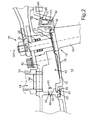
- This gap 38 is also referred to as a flag gap and is particularly good in Fig. 2 to recognize.
- this flag gap 38 In order to reduce the fuel consumption of the gas turbine, this flag gap 38 should be closed during operation as good as possible or be. Otherwise, strong throttling losses occur due to overflow and induction of turbulence. Therefore, the wall element 12 is between a sealing position, in which the wall element 12 abuts at least a portion of a wall element 12 facing side 40 of the blade 30 of the vane 18, and an open position, in which the blade 30 and the wall element 12 are spaced apart, movable.
- the sealing position of the wall element 12 is in Fig. 2 shown by solid lines, the open position with dashed lines. It is easy to see how the wall element 12 rests in the sealing position on the side 40 of the blade 30, whereby the flag gap 38 is substantially closed.
- the wall element 12 can be acted upon by a pressure for moving between the sealing position and the open position.
- the wall member 12 and an adjacent housing member 42 define a cavity 44.
- the cavity 44 is also referred to as a cavity.
- This cavity 44 is supplied via a trained as a bore 46 pressure supply line 48 with pressure.
- the pressure can be generated by ram air, which arises during the movement of an aircraft, helicopter or the like.
- bleed air from a compressor stage of the gas turbine can also be used for pressurizing the cavity 44, wherein the compressor stage is also referred to as a compressor stage.
- This pressure in the cavity 44 exerts a force on the wall element 12 so that it is moved or pressed against the side 40 of the airfoil 30.
- the congestion or bleed air can preferably also serve as cooling air for cooling the turbine housing. It can escape at least partially as a leakage flow through remaining openings or gaps to the hot gas or flow channel 14 in the latter from the cavity 44, thereby preventing hot gas from the hot gas or flow channel 14 through the openings or gaps in the cavity 44 is sucked.
- the wall element 12 Since the wall element 12 according to the present invention is designed to be movable between the sealing position and the open position, the guide vane 18, apart from a possible rotation about its axis of rotation D2, is fixed relative to the rest of the turbine housing, there is a clearance fit with a small annular gap between the wall element 12 and the vane 18 is provided. Through the annular gap of this clearance, for example, a portion of the cooling air from the cavity 44 into which the hot gas or flow channel 14 exit. If necessary, however, a sealing element, not illustrated here, can also be provided on this annular gap, in order at least largely to prevent a leakage flow.
- the housing 10 comprises a pressure discharge 50, by means of which a pressure in the cavity 44 can be reduced by fading of fluid.
- the pressure discharge 50 lead into the environment and thus blow off existing compressed air in the cavity 44.
- the wall member 12 is forced radially outwardly by the pressure difference between the pressure in the cavity 44 and a pressure in the flow channel 14, so that it is moved to the open position.
- this movement can also be effected and / or assisted by a spring element.
- the pressure discharge 50 comprises a switchable valve 52, by means of which the pressure can be controlled or regulated.
- the switchable valve 52 is in Fig. 1 only symbolically represented.
- the pressure in the cavity 44 can be increased by compressed air flowing through the pressure supply line 48 into the cavity 44 and can not escape through the closed by the valve 52 pressure discharge line 50.
- the wall element 12 is moved into the sealing position.
- the switchable valve 52 is opened, compressed air flows out of the cavity 44 via the pressure discharge line 50.
- the wall element 12 As soon as the pressure in the cavity 44 has become smaller than the pressure in the flow channel 14, the wall element 12 is thus moved into the open position and releases the flag gap 38, so that the guide vane 18 can be adjusted, without causing wear due to friction with the wall element 12 is coming.
- the valve 52 By means of the valve 52, therefore, the wall element 12 can be moved as required between the sealing position and the open position during operation of the gas turbine.
- the pressure in the cavity 44 is reduced only briefly, ie less than 10 seconds, preferably less than 2 seconds, more preferably less than 2 seconds, under the pressure in the flow channel 14, namely substantially only as long as the adjustment of the Guide vane 18 needed in time. This prevents the turbine housing from overheating during this time due to hot gas intake and the lack of supply of cooling air.
- a blow-off channel 54 of the pressure discharge line 50 has a larger cross section 56 than an access channel 58 of the pressure supply line.
- the cross section of the access channel 58 is in Fig. 2 designated by the reference numeral 60.
- the larger cross-section 56 of the Abblasskanals 54 allows a faster outflow of compressed air from the cavity 44, as can flow through the access port 58.
- the pressure supply line 48 may comprise a switchable valve.
- the pressure feed line 48 or its cross section 60 is preferably selected to be so large that an equilibrium is established between the inflow of compressed air into the cavity 44 and an outflow through leaks in the housing 10. That is, it flows in a closed valve 52 just as much compressed air, which is ensured in the cavity 44, a substantially constant pressure, which holds the wall member 12 in the sealing position. Therefore, the supply of the pressurized fluid should be selected such that not so much pressure escapes through leaks from the cavity 44, that the wall element 12 moves unintentionally in the open position. Likewise, it should not come to an undue increase in the pressure in the cavity 44.
- a pressure relief valve or a corresponding overpressure limitation can be provided by the valve 52.
- the wall element 12 has a one-sided bearing 62 on the housing element 42.
- a nose element 64 of the wall element 12 is inserted into a groove 66 of the housing element 42.
- the wall element 12 In the open position, the wall element 12 is pivoted on its side facing away from the bearing 62 62 radially outward with respect to the flow channel 14 or bent.
- the wall element 12 In the sealing position, the wall element 12 is pivoted or bent on the side 68 radially in the direction of the flow channel 14.
- the wall element 12 can also be rotatably held on a hinge on the bearing 62.
- the wall element 12 on the side facing away from the bearing 62 68 performs the largest relative movement to the housing member 42 in a movement between the sealing position and the open position. In this case, a gap between the wall element 12 and the housing element 42 is released.
- a sealing element 70 is arranged at this point. During the movement of the wall element 12, this slides along the sealing element 70.
- the wall element 12 comprises an opening 72 in which a blade plate 74 of the guide blade 18 is arranged.
- a clearance fit for example in the form of a small annular gap, is provided between the blade plate 74 and the opening 72, which makes it possible to rotate the guide blade 18 about the rotation axis D2 and largely reduces pressure losses in the flow channel 14.
- a surface 76 delimiting the flow channel 14 of the wall element 12 and the blade plate 74 adjoin one another flush in the sealing position. That is, the wall member 12 and the blade plate 74 define the flow channel 14 in the radially outward direction with an aerodynamically uniform surface so as to avoid inducing swirls or other undesirable aerodynamic phenomena in the gas flow in the flow channel 14.
- the guide vane 18 By moving in the sealing position wall member 12, the guide vane 18 is frictionally fixed thereto. Thus, the guide vane 18 is held against rotation on the wall element 12, so that can be advantageously dispensed with additional elements for fixing the vane 18.
- a stop element 78 is provided for limiting the movement of the Wandungselements 12 in the open position and a stop member 80 for limiting the movement of the Wandungselements 12 in the sealing position.
- the stop element 78 of the housing 10 is designed as a nose element.
- a corresponding nose element 82 of the wall element 12 abuts against the stop element 78 in the open position. This is particularly reliably prevents the wall element 12 is bent too far radially outward by a too high pressure difference between the flow channel 14 and the cavity 44 in the open position and thereby either itself is damaged or damaged the housing member 42.
- the stopper member 80 is formed as an edge in the housing member 42 on which a corresponding one Nose element 84 of the Wandungselements 12 can come into sealing position to the plant. This prevents that the wall element 12 moves inadmissibly far radially inward or bends. In addition, the blade 30 is protected from damage by excessive movement of the wall member 12.
- the gas turbine shown or the aircraft engine shown is operated as follows: As soon as an operating state is present, which requires an adjustment of the guide vane 18, the wall element 12 is moved from the sealing position to the open position. For this purpose, the switchable valve 52 is opened and compressed air flows out of the cavity 44 via the pressure discharge line 50. As a result, the pressure acting on the wall element 12 is reduced in the cavity 44. Due to the prevailing pressure in the flow channel 14, the wall element 12 is moved or bent into the open position and thus releases the flag gap 38. Thus, the guide vane 18 can be rotated about the axis of rotation D2 by means of the adjusting device until an optimum flow of the turbine blade 20 is set for the relevant operating point.
- the switchable valve 52 is closed again. Compressed air flowing through the pressure feed line 48 into the hollow space 44 exerts a pressure on the wall element 12, which acts on the wall element 12 radially from the outside from the hollow space 44. Accordingly, the wall element 12 is moved back into the sealing position or bent and the flag gap 38 at least largely closed. Due to the flag gap 38 and possibly other gaps during the adjustment movement of the wall element 12 and the guide vanes 18 occur so only short-term losses, which are negligible for the fuel consumption over the entire duration of flight of the aircraft, helicopters or the like. In contrast, external losses in the flow channel 14 are almost completely avoided during the remaining operation of the gas turbine or the aircraft engine, resulting in a significant efficiency gain.
- the wall element 12 relative to it in the circumferential direction adjacent further wall elements which may be formed identical to the wall element 12, for example by means not shown sealing plates which are provided in corresponding sealing grooves of the wall element 12 may be sealed, as this From the prior art is well known.
- a high degree of tightness between the circumferentially adjacent wall elements can be achieved both in the sealing position and in the open position and the transition between these positions.
- all Verstellleitschaufeln be adjusted at the same time, so that all their associated wall elements 12 are simultaneously transferred from the sealing position to the open position and back.
Landscapes
- Engineering & Computer Science (AREA)
- Mechanical Engineering (AREA)
- General Engineering & Computer Science (AREA)
- Control Of Turbines (AREA)
- Structures Of Non-Positive Displacement Pumps (AREA)
Applications Claiming Priority (1)
| Application Number | Priority Date | Filing Date | Title |
|---|---|---|---|
| DE102014214915.0A DE102014214915B3 (de) | 2014-07-30 | 2014-07-30 | Gehäuse für eine Gasturbine, Flugtriebwerk sowie ein Verfahren zum Betreiben einer Gasturbine |
Publications (2)
| Publication Number | Publication Date |
|---|---|
| EP2980366A1 true EP2980366A1 (fr) | 2016-02-03 |
| EP2980366B1 EP2980366B1 (fr) | 2020-04-08 |
Family
ID=53835875
Family Applications (1)
| Application Number | Title | Priority Date | Filing Date |
|---|---|---|---|
| EP15176353.9A Active EP2980366B1 (fr) | 2014-07-30 | 2015-07-10 | Boîtier pour une turbine à gaz, groupe motopropulseur et procédé de fonctionnement d'une turbine à gaz |
Country Status (4)
| Country | Link |
|---|---|
| US (1) | US9988927B2 (fr) |
| EP (1) | EP2980366B1 (fr) |
| DE (1) | DE102014214915B3 (fr) |
| ES (1) | ES2790578T3 (fr) |
Cited By (1)
| Publication number | Priority date | Publication date | Assignee | Title |
|---|---|---|---|---|
| CN109209525A (zh) * | 2018-11-23 | 2019-01-15 | 陈济颖 | 一种高背压蒸汽轮机组 |
Families Citing this family (5)
| Publication number | Priority date | Publication date | Assignee | Title |
|---|---|---|---|---|
| EP2960438B1 (fr) * | 2014-06-26 | 2020-09-02 | MTU Aero Engines GmbH | Système d'aubes de guidage variables pour une turbine à gaz et turbine à gaz dotée d'un tel système |
| GB2552048A (en) * | 2016-03-22 | 2018-01-10 | Gen Electric | Method, system, and apparatus for reducing a turbine clearance |
| DE102016110269A1 (de) * | 2016-06-03 | 2017-12-07 | Man Diesel & Turbo Se | Axialturbine eines Turboladers und Turbolader |
| CN109751089B (zh) * | 2017-11-03 | 2023-09-19 | 长兴永能动力科技有限公司 | 一种向心式汽轮机可调喷嘴 |
| DE102022128618A1 (de) * | 2022-10-28 | 2024-05-08 | Atlas Copco Energas Gmbh | Turbomaschinen und Verfahren zum Betrieb einer Turbomaschine |
Citations (4)
| Publication number | Priority date | Publication date | Assignee | Title |
|---|---|---|---|---|
| US2919809A (en) | 1958-12-19 | 1960-01-05 | Cal Dak Company Inc | Rack |
| US5873700A (en) * | 1996-01-26 | 1999-02-23 | Hitachi, Ltd. | Hydraulic machine |
| WO2007045874A1 (fr) * | 2005-10-20 | 2007-04-26 | Cummins Turbo Technologies Limited | Turbine avec geometrie de tuyere d’entree variable |
| EP2407673A1 (fr) * | 2010-07-12 | 2012-01-18 | Siemens Aktiengesellschaft | Compresseur |
Family Cites Families (5)
| Publication number | Priority date | Publication date | Assignee | Title |
|---|---|---|---|---|
| US2919890A (en) * | 1955-09-16 | 1960-01-05 | Gen Electric | Adjustable gas turbine nozzle assembly |
| DE2931766C2 (de) | 1979-08-04 | 1982-08-05 | MTU Motoren- und Turbinen-Union München GmbH, 8000 München | Dichtungseinrichtung für die freien Schaufelenden eines Verstell-Leitapparates einer Gasturbine |
| DE19961613A1 (de) * | 1999-12-21 | 2001-07-19 | Daimler Chrysler Ag | Abgasturbine eines Abgasturboladers für eine Brennkraftmaschine |
| US9133726B2 (en) * | 2007-09-17 | 2015-09-15 | United Technologies Corporation | Seal for gas turbine engine component |
| FR2938293B1 (fr) * | 2008-11-12 | 2015-08-21 | Snecma | Dispositif de regulation du debit d'air alimentant une cavite de ventillation de turbine d'une section de turbine de turbomachine |
-
2014
- 2014-07-30 DE DE102014214915.0A patent/DE102014214915B3/de not_active Expired - Fee Related
-
2015
- 2015-07-10 EP EP15176353.9A patent/EP2980366B1/fr active Active
- 2015-07-10 ES ES15176353T patent/ES2790578T3/es active Active
- 2015-07-29 US US14/812,204 patent/US9988927B2/en active Active
Patent Citations (4)
| Publication number | Priority date | Publication date | Assignee | Title |
|---|---|---|---|---|
| US2919809A (en) | 1958-12-19 | 1960-01-05 | Cal Dak Company Inc | Rack |
| US5873700A (en) * | 1996-01-26 | 1999-02-23 | Hitachi, Ltd. | Hydraulic machine |
| WO2007045874A1 (fr) * | 2005-10-20 | 2007-04-26 | Cummins Turbo Technologies Limited | Turbine avec geometrie de tuyere d’entree variable |
| EP2407673A1 (fr) * | 2010-07-12 | 2012-01-18 | Siemens Aktiengesellschaft | Compresseur |
Cited By (1)
| Publication number | Priority date | Publication date | Assignee | Title |
|---|---|---|---|---|
| CN109209525A (zh) * | 2018-11-23 | 2019-01-15 | 陈济颖 | 一种高背压蒸汽轮机组 |
Also Published As
| Publication number | Publication date |
|---|---|
| EP2980366B1 (fr) | 2020-04-08 |
| US20160032760A1 (en) | 2016-02-04 |
| ES2790578T3 (es) | 2020-10-28 |
| US9988927B2 (en) | 2018-06-05 |
| DE102014214915B3 (de) | 2015-12-10 |
Similar Documents
| Publication | Publication Date | Title |
|---|---|---|
| EP2980366B1 (fr) | Boîtier pour une turbine à gaz, groupe motopropulseur et procédé de fonctionnement d'une turbine à gaz | |
| DE102011054468B4 (de) | Variables Turbinenleitapparatsystem | |
| EP3388649B1 (fr) | Nacelle de moteur pour une turbosoufflante | |
| EP3306066B1 (fr) | Turbine à double flux pour un avion supersonique civil | |
| EP2835522B2 (fr) | Dispositif et procédé de soufflage d'air comprimé dans une turbine | |
| EP2955335B1 (fr) | Stator, aube directrice, bague intérieure et turbomachine | |
| DE2042478A1 (de) | Gasturbinenstrahltriebwerk für Flugzeuge mit Einrichtungen zur Bauteilkühlung und Verdichterregelung | |
| DE102011053712A1 (de) | Windturbinenrotorblatt mit betätigbaren profilpassagen | |
| DE4003802A1 (de) | Spaltregulierung für die Turbine eines Gasturbinentriebwerks | |
| DE102008028987A1 (de) | Turboproptriebwerk mit einer Vorrichtung zum Erzeugen eines Kühlluftstroms | |
| EP2596213B1 (fr) | Turbine à vapeur avec un refroidissement interne | |
| DE4214775A1 (de) | Dampfturbine mit einem Drehschieber | |
| EP2980365A1 (fr) | Aube directrice pour turbine à gaz avec eléments d'étanchéité aux extrémités | |
| EP2617947B1 (fr) | Turbine à gaz d'avion avec soufflante ajustable | |
| DE602005005903T2 (de) | Zusammenbau einer Nasenhaube einer Turbomaschine und einer Fanschaufel-Welle. | |
| DE102011103518A1 (de) | Abblaseventil | |
| DE102013002192A1 (de) | Turbine für einen Abgasturbolader | |
| DE2629049A1 (de) | Duese mit variablem querschnitt und belastungsausgleich | |
| EP2146056A2 (fr) | Turbine à gaz avec aubes directrices variables | |
| DE1274412B (de) | Verriegelungsvorrichtung | |
| WO2014012725A1 (fr) | Diffuseur parallèle pour une machine à fluide | |
| DE102019000252A1 (de) | Axialschieber-Turbine mit axial verschiebbarem Leitgitterträger | |
| WO2013072294A2 (fr) | Turbocompresseur à gaz d'échappement présentant une géométrie de turbine variable et une rondelle ressort d'étanchéité | |
| WO2017097665A1 (fr) | Turbine à gaz d'aéronef à tuyère de sortie variable d'un canal de flux secondaire | |
| EP1541803A2 (fr) | Arrangement de soulagement des paliers dans une turbine à gaz |
Legal Events
| Date | Code | Title | Description |
|---|---|---|---|
| PUAI | Public reference made under article 153(3) epc to a published international application that has entered the european phase |
Free format text: ORIGINAL CODE: 0009012 |
|
| AK | Designated contracting states |
Kind code of ref document: A1 Designated state(s): AL AT BE BG CH CY CZ DE DK EE ES FI FR GB GR HR HU IE IS IT LI LT LU LV MC MK MT NL NO PL PT RO RS SE SI SK SM TR |
|
| AX | Request for extension of the european patent |
Extension state: BA ME |
|
| 17P | Request for examination filed |
Effective date: 20160727 |
|
| RBV | Designated contracting states (corrected) |
Designated state(s): AL AT BE BG CH CY CZ DE DK EE ES FI FR GB GR HR HU IE IS IT LI LT LU LV MC MK MT NL NO PL PT RO RS SE SI SK SM TR |
|
| RIC1 | Information provided on ipc code assigned before grant |
Ipc: F04D 29/56 20060101ALI20190924BHEP Ipc: F01D 17/16 20060101AFI20190924BHEP Ipc: F01D 9/04 20060101ALI20190924BHEP |
|
| GRAP | Despatch of communication of intention to grant a patent |
Free format text: ORIGINAL CODE: EPIDOSNIGR1 |
|
| STAA | Information on the status of an ep patent application or granted ep patent |
Free format text: STATUS: GRANT OF PATENT IS INTENDED |
|
| INTG | Intention to grant announced |
Effective date: 20191105 |
|
| GRAS | Grant fee paid |
Free format text: ORIGINAL CODE: EPIDOSNIGR3 |
|
| GRAA | (expected) grant |
Free format text: ORIGINAL CODE: 0009210 |
|
| STAA | Information on the status of an ep patent application or granted ep patent |
Free format text: STATUS: THE PATENT HAS BEEN GRANTED |
|
| AK | Designated contracting states |
Kind code of ref document: B1 Designated state(s): AL AT BE BG CH CY CZ DE DK EE ES FI FR GB GR HR HU IE IS IT LI LT LU LV MC MK MT NL NO PL PT RO RS SE SI SK SM TR |
|
| REG | Reference to a national code |
Ref country code: AT Ref legal event code: REF Ref document number: 1254659 Country of ref document: AT Kind code of ref document: T Effective date: 20200415 Ref country code: CH Ref legal event code: EP |
|
| REG | Reference to a national code |
Ref country code: IE Ref legal event code: FG4D Free format text: LANGUAGE OF EP DOCUMENT: GERMAN |
|
| REG | Reference to a national code |
Ref country code: DE Ref legal event code: R096 Ref document number: 502015012200 Country of ref document: DE |
|
| REG | Reference to a national code |
Ref country code: NL Ref legal event code: MP Effective date: 20200408 |
|
| REG | Reference to a national code |
Ref country code: LT Ref legal event code: MG4D |
|
| REG | Reference to a national code |
Ref country code: ES Ref legal event code: FG2A Ref document number: 2790578 Country of ref document: ES Kind code of ref document: T3 Effective date: 20201028 |
|
| PG25 | Lapsed in a contracting state [announced via postgrant information from national office to epo] |
Ref country code: FI Free format text: LAPSE BECAUSE OF FAILURE TO SUBMIT A TRANSLATION OF THE DESCRIPTION OR TO PAY THE FEE WITHIN THE PRESCRIBED TIME-LIMIT Effective date: 20200408 Ref country code: SE Free format text: LAPSE BECAUSE OF FAILURE TO SUBMIT A TRANSLATION OF THE DESCRIPTION OR TO PAY THE FEE WITHIN THE PRESCRIBED TIME-LIMIT Effective date: 20200408 Ref country code: LT Free format text: LAPSE BECAUSE OF FAILURE TO SUBMIT A TRANSLATION OF THE DESCRIPTION OR TO PAY THE FEE WITHIN THE PRESCRIBED TIME-LIMIT Effective date: 20200408 Ref country code: NL Free format text: LAPSE BECAUSE OF FAILURE TO SUBMIT A TRANSLATION OF THE DESCRIPTION OR TO PAY THE FEE WITHIN THE PRESCRIBED TIME-LIMIT Effective date: 20200408 Ref country code: GR Free format text: LAPSE BECAUSE OF FAILURE TO SUBMIT A TRANSLATION OF THE DESCRIPTION OR TO PAY THE FEE WITHIN THE PRESCRIBED TIME-LIMIT Effective date: 20200709 Ref country code: NO Free format text: LAPSE BECAUSE OF FAILURE TO SUBMIT A TRANSLATION OF THE DESCRIPTION OR TO PAY THE FEE WITHIN THE PRESCRIBED TIME-LIMIT Effective date: 20200708 Ref country code: IS Free format text: LAPSE BECAUSE OF FAILURE TO SUBMIT A TRANSLATION OF THE DESCRIPTION OR TO PAY THE FEE WITHIN THE PRESCRIBED TIME-LIMIT Effective date: 20200808 Ref country code: PT Free format text: LAPSE BECAUSE OF FAILURE TO SUBMIT A TRANSLATION OF THE DESCRIPTION OR TO PAY THE FEE WITHIN THE PRESCRIBED TIME-LIMIT Effective date: 20200817 |
|
| PG25 | Lapsed in a contracting state [announced via postgrant information from national office to epo] |
Ref country code: RS Free format text: LAPSE BECAUSE OF FAILURE TO SUBMIT A TRANSLATION OF THE DESCRIPTION OR TO PAY THE FEE WITHIN THE PRESCRIBED TIME-LIMIT Effective date: 20200408 Ref country code: BG Free format text: LAPSE BECAUSE OF FAILURE TO SUBMIT A TRANSLATION OF THE DESCRIPTION OR TO PAY THE FEE WITHIN THE PRESCRIBED TIME-LIMIT Effective date: 20200708 Ref country code: LV Free format text: LAPSE BECAUSE OF FAILURE TO SUBMIT A TRANSLATION OF THE DESCRIPTION OR TO PAY THE FEE WITHIN THE PRESCRIBED TIME-LIMIT Effective date: 20200408 Ref country code: HR Free format text: LAPSE BECAUSE OF FAILURE TO SUBMIT A TRANSLATION OF THE DESCRIPTION OR TO PAY THE FEE WITHIN THE PRESCRIBED TIME-LIMIT Effective date: 20200408 |
|
| PG25 | Lapsed in a contracting state [announced via postgrant information from national office to epo] |
Ref country code: AL Free format text: LAPSE BECAUSE OF FAILURE TO SUBMIT A TRANSLATION OF THE DESCRIPTION OR TO PAY THE FEE WITHIN THE PRESCRIBED TIME-LIMIT Effective date: 20200408 |
|
| REG | Reference to a national code |
Ref country code: DE Ref legal event code: R097 Ref document number: 502015012200 Country of ref document: DE |
|
| PG25 | Lapsed in a contracting state [announced via postgrant information from national office to epo] |
Ref country code: DK Free format text: LAPSE BECAUSE OF FAILURE TO SUBMIT A TRANSLATION OF THE DESCRIPTION OR TO PAY THE FEE WITHIN THE PRESCRIBED TIME-LIMIT Effective date: 20200408 Ref country code: EE Free format text: LAPSE BECAUSE OF FAILURE TO SUBMIT A TRANSLATION OF THE DESCRIPTION OR TO PAY THE FEE WITHIN THE PRESCRIBED TIME-LIMIT Effective date: 20200408 Ref country code: SM Free format text: LAPSE BECAUSE OF FAILURE TO SUBMIT A TRANSLATION OF THE DESCRIPTION OR TO PAY THE FEE WITHIN THE PRESCRIBED TIME-LIMIT Effective date: 20200408 Ref country code: RO Free format text: LAPSE BECAUSE OF FAILURE TO SUBMIT A TRANSLATION OF THE DESCRIPTION OR TO PAY THE FEE WITHIN THE PRESCRIBED TIME-LIMIT Effective date: 20200408 Ref country code: IT Free format text: LAPSE BECAUSE OF FAILURE TO SUBMIT A TRANSLATION OF THE DESCRIPTION OR TO PAY THE FEE WITHIN THE PRESCRIBED TIME-LIMIT Effective date: 20200408 Ref country code: CZ Free format text: LAPSE BECAUSE OF FAILURE TO SUBMIT A TRANSLATION OF THE DESCRIPTION OR TO PAY THE FEE WITHIN THE PRESCRIBED TIME-LIMIT Effective date: 20200408 |
|
| PLBE | No opposition filed within time limit |
Free format text: ORIGINAL CODE: 0009261 |
|
| STAA | Information on the status of an ep patent application or granted ep patent |
Free format text: STATUS: NO OPPOSITION FILED WITHIN TIME LIMIT |
|
| PG25 | Lapsed in a contracting state [announced via postgrant information from national office to epo] |
Ref country code: PL Free format text: LAPSE BECAUSE OF FAILURE TO SUBMIT A TRANSLATION OF THE DESCRIPTION OR TO PAY THE FEE WITHIN THE PRESCRIBED TIME-LIMIT Effective date: 20200408 Ref country code: SK Free format text: LAPSE BECAUSE OF FAILURE TO SUBMIT A TRANSLATION OF THE DESCRIPTION OR TO PAY THE FEE WITHIN THE PRESCRIBED TIME-LIMIT Effective date: 20200408 Ref country code: MC Free format text: LAPSE BECAUSE OF FAILURE TO SUBMIT A TRANSLATION OF THE DESCRIPTION OR TO PAY THE FEE WITHIN THE PRESCRIBED TIME-LIMIT Effective date: 20200408 |
|
| REG | Reference to a national code |
Ref country code: CH Ref legal event code: PL |
|
| 26N | No opposition filed |
Effective date: 20210112 |
|
| REG | Reference to a national code |
Ref country code: BE Ref legal event code: MM Effective date: 20200731 |
|
| PG25 | Lapsed in a contracting state [announced via postgrant information from national office to epo] |
Ref country code: CH Free format text: LAPSE BECAUSE OF NON-PAYMENT OF DUE FEES Effective date: 20200731 Ref country code: LU Free format text: LAPSE BECAUSE OF NON-PAYMENT OF DUE FEES Effective date: 20200710 Ref country code: LI Free format text: LAPSE BECAUSE OF NON-PAYMENT OF DUE FEES Effective date: 20200731 |
|
| PG25 | Lapsed in a contracting state [announced via postgrant information from national office to epo] |
Ref country code: BE Free format text: LAPSE BECAUSE OF NON-PAYMENT OF DUE FEES Effective date: 20200731 Ref country code: SI Free format text: LAPSE BECAUSE OF FAILURE TO SUBMIT A TRANSLATION OF THE DESCRIPTION OR TO PAY THE FEE WITHIN THE PRESCRIBED TIME-LIMIT Effective date: 20200408 |
|
| PG25 | Lapsed in a contracting state [announced via postgrant information from national office to epo] |
Ref country code: IE Free format text: LAPSE BECAUSE OF NON-PAYMENT OF DUE FEES Effective date: 20200710 |
|
| REG | Reference to a national code |
Ref country code: AT Ref legal event code: MM01 Ref document number: 1254659 Country of ref document: AT Kind code of ref document: T Effective date: 20200710 |
|
| PG25 | Lapsed in a contracting state [announced via postgrant information from national office to epo] |
Ref country code: AT Free format text: LAPSE BECAUSE OF NON-PAYMENT OF DUE FEES Effective date: 20200710 |
|
| PG25 | Lapsed in a contracting state [announced via postgrant information from national office to epo] |
Ref country code: TR Free format text: LAPSE BECAUSE OF FAILURE TO SUBMIT A TRANSLATION OF THE DESCRIPTION OR TO PAY THE FEE WITHIN THE PRESCRIBED TIME-LIMIT Effective date: 20200408 Ref country code: MT Free format text: LAPSE BECAUSE OF FAILURE TO SUBMIT A TRANSLATION OF THE DESCRIPTION OR TO PAY THE FEE WITHIN THE PRESCRIBED TIME-LIMIT Effective date: 20200408 Ref country code: CY Free format text: LAPSE BECAUSE OF FAILURE TO SUBMIT A TRANSLATION OF THE DESCRIPTION OR TO PAY THE FEE WITHIN THE PRESCRIBED TIME-LIMIT Effective date: 20200408 |
|
| PG25 | Lapsed in a contracting state [announced via postgrant information from national office to epo] |
Ref country code: MK Free format text: LAPSE BECAUSE OF FAILURE TO SUBMIT A TRANSLATION OF THE DESCRIPTION OR TO PAY THE FEE WITHIN THE PRESCRIBED TIME-LIMIT Effective date: 20200408 |
|
| PGFP | Annual fee paid to national office [announced via postgrant information from national office to epo] |
Ref country code: GB Payment date: 20220725 Year of fee payment: 8 Ref country code: ES Payment date: 20220819 Year of fee payment: 8 Ref country code: DE Payment date: 20220621 Year of fee payment: 8 |
|
| PGFP | Annual fee paid to national office [announced via postgrant information from national office to epo] |
Ref country code: FR Payment date: 20220727 Year of fee payment: 8 |
|
| REG | Reference to a national code |
Ref country code: DE Ref legal event code: R119 Ref document number: 502015012200 Country of ref document: DE |
|
| GBPC | Gb: european patent ceased through non-payment of renewal fee |
Effective date: 20230710 |
|
| PG25 | Lapsed in a contracting state [announced via postgrant information from national office to epo] |
Ref country code: DE Free format text: LAPSE BECAUSE OF NON-PAYMENT OF DUE FEES Effective date: 20240201 Ref country code: GB Free format text: LAPSE BECAUSE OF NON-PAYMENT OF DUE FEES Effective date: 20230710 |
|
| PG25 | Lapsed in a contracting state [announced via postgrant information from national office to epo] |
Ref country code: FR Free format text: LAPSE BECAUSE OF NON-PAYMENT OF DUE FEES Effective date: 20230731 |
|
| REG | Reference to a national code |
Ref country code: ES Ref legal event code: FD2A Effective date: 20240828 |
|
| PG25 | Lapsed in a contracting state [announced via postgrant information from national office to epo] |
Ref country code: ES Free format text: LAPSE BECAUSE OF NON-PAYMENT OF DUE FEES Effective date: 20230711 |
|
| PG25 | Lapsed in a contracting state [announced via postgrant information from national office to epo] |
Ref country code: ES Free format text: LAPSE BECAUSE OF NON-PAYMENT OF DUE FEES Effective date: 20230711 |