EP2980379A1 - Dispositif d'injection et procede de fabrication associe - Google Patents
Dispositif d'injection et procede de fabrication associe Download PDFInfo
- Publication number
- EP2980379A1 EP2980379A1 EP15172830.0A EP15172830A EP2980379A1 EP 2980379 A1 EP2980379 A1 EP 2980379A1 EP 15172830 A EP15172830 A EP 15172830A EP 2980379 A1 EP2980379 A1 EP 2980379A1
- Authority
- EP
- European Patent Office
- Prior art keywords
- exhaust pipe
- nozzle
- shell
- wall
- nozzle opening
- Prior art date
- Legal status (The legal status is an assumption and is not a legal conclusion. Google has not performed a legal analysis and makes no representation as to the accuracy of the status listed.)
- Granted
Links
Images

Classifications
-
- F—MECHANICAL ENGINEERING; LIGHTING; HEATING; WEAPONS; BLASTING
- F01—MACHINES OR ENGINES IN GENERAL; ENGINE PLANTS IN GENERAL; STEAM ENGINES
- F01N—GAS-FLOW SILENCERS OR EXHAUST APPARATUS FOR MACHINES OR ENGINES IN GENERAL; GAS-FLOW SILENCERS OR EXHAUST APPARATUS FOR INTERNAL-COMBUSTION ENGINES
- F01N3/00—Exhaust or silencing apparatus having means for purifying, rendering innocuous, or otherwise treating exhaust
- F01N3/08—Exhaust or silencing apparatus having means for purifying, rendering innocuous, or otherwise treating exhaust for rendering innocuous
- F01N3/10—Exhaust or silencing apparatus having means for purifying, rendering innocuous, or otherwise treating exhaust for rendering innocuous by thermal or catalytic conversion of noxious components of exhaust
- F01N3/18—Exhaust or silencing apparatus having means for purifying, rendering innocuous, or otherwise treating exhaust for rendering innocuous by thermal or catalytic conversion of noxious components of exhaust characterised by methods of operation; Control
- F01N3/20—Exhaust or silencing apparatus having means for purifying, rendering innocuous, or otherwise treating exhaust for rendering innocuous by thermal or catalytic conversion of noxious components of exhaust characterised by methods of operation; Control specially adapted for catalytic conversion
- F01N3/206—Adding periodically or continuously substances to exhaust gases for promoting purification, e.g. catalytic material in liquid form, NOx reducing agents
- F01N3/2066—Selective catalytic reduction [SCR]
-
- F—MECHANICAL ENGINEERING; LIGHTING; HEATING; WEAPONS; BLASTING
- F01—MACHINES OR ENGINES IN GENERAL; ENGINE PLANTS IN GENERAL; STEAM ENGINES
- F01N—GAS-FLOW SILENCERS OR EXHAUST APPARATUS FOR MACHINES OR ENGINES IN GENERAL; GAS-FLOW SILENCERS OR EXHAUST APPARATUS FOR INTERNAL-COMBUSTION ENGINES
- F01N13/00—Exhaust or silencing apparatus characterised by constructional features
- F01N13/08—Other arrangements or adaptations of exhaust conduits
-
- F—MECHANICAL ENGINEERING; LIGHTING; HEATING; WEAPONS; BLASTING
- F01—MACHINES OR ENGINES IN GENERAL; ENGINE PLANTS IN GENERAL; STEAM ENGINES
- F01N—GAS-FLOW SILENCERS OR EXHAUST APPARATUS FOR MACHINES OR ENGINES IN GENERAL; GAS-FLOW SILENCERS OR EXHAUST APPARATUS FOR INTERNAL-COMBUSTION ENGINES
- F01N13/00—Exhaust or silencing apparatus characterised by constructional features
- F01N13/18—Construction facilitating manufacture, assembly, or disassembly
- F01N13/1838—Construction facilitating manufacture, assembly, or disassembly characterised by the type of connection between parts of exhaust or silencing apparatus, e.g. between housing and tubes, between tubes and baffles
-
- F—MECHANICAL ENGINEERING; LIGHTING; HEATING; WEAPONS; BLASTING
- F01—MACHINES OR ENGINES IN GENERAL; ENGINE PLANTS IN GENERAL; STEAM ENGINES
- F01N—GAS-FLOW SILENCERS OR EXHAUST APPARATUS FOR MACHINES OR ENGINES IN GENERAL; GAS-FLOW SILENCERS OR EXHAUST APPARATUS FOR INTERNAL-COMBUSTION ENGINES
- F01N13/00—Exhaust or silencing apparatus characterised by constructional features
- F01N13/18—Construction facilitating manufacture, assembly, or disassembly
- F01N13/1838—Construction facilitating manufacture, assembly, or disassembly characterised by the type of connection between parts of exhaust or silencing apparatus, e.g. between housing and tubes, between tubes and baffles
- F01N13/1844—Mechanical joints
- F01N13/185—Mechanical joints the connection being realised by deforming housing, tube, baffle, plate, or parts thereof
-
- F—MECHANICAL ENGINEERING; LIGHTING; HEATING; WEAPONS; BLASTING
- F01—MACHINES OR ENGINES IN GENERAL; ENGINE PLANTS IN GENERAL; STEAM ENGINES
- F01N—GAS-FLOW SILENCERS OR EXHAUST APPARATUS FOR MACHINES OR ENGINES IN GENERAL; GAS-FLOW SILENCERS OR EXHAUST APPARATUS FOR INTERNAL-COMBUSTION ENGINES
- F01N13/00—Exhaust or silencing apparatus characterised by constructional features
- F01N13/18—Construction facilitating manufacture, assembly, or disassembly
- F01N13/1888—Construction facilitating manufacture, assembly, or disassembly the housing of the assembly consisting of two or more parts, e.g. two half-shells
-
- F—MECHANICAL ENGINEERING; LIGHTING; HEATING; WEAPONS; BLASTING
- F01—MACHINES OR ENGINES IN GENERAL; ENGINE PLANTS IN GENERAL; STEAM ENGINES
- F01N—GAS-FLOW SILENCERS OR EXHAUST APPARATUS FOR MACHINES OR ENGINES IN GENERAL; GAS-FLOW SILENCERS OR EXHAUST APPARATUS FOR INTERNAL-COMBUSTION ENGINES
- F01N3/00—Exhaust or silencing apparatus having means for purifying, rendering innocuous, or otherwise treating exhaust
- F01N3/08—Exhaust or silencing apparatus having means for purifying, rendering innocuous, or otherwise treating exhaust for rendering innocuous
- F01N3/10—Exhaust or silencing apparatus having means for purifying, rendering innocuous, or otherwise treating exhaust for rendering innocuous by thermal or catalytic conversion of noxious components of exhaust
- F01N3/24—Exhaust or silencing apparatus having means for purifying, rendering innocuous, or otherwise treating exhaust for rendering innocuous by thermal or catalytic conversion of noxious components of exhaust characterised by constructional aspects of converting apparatus
- F01N3/28—Construction of catalytic reactors
- F01N3/2892—Exhaust flow directors or the like, e.g. upstream of catalytic device
-
- F—MECHANICAL ENGINEERING; LIGHTING; HEATING; WEAPONS; BLASTING
- F01—MACHINES OR ENGINES IN GENERAL; ENGINE PLANTS IN GENERAL; STEAM ENGINES
- F01N—GAS-FLOW SILENCERS OR EXHAUST APPARATUS FOR MACHINES OR ENGINES IN GENERAL; GAS-FLOW SILENCERS OR EXHAUST APPARATUS FOR INTERNAL-COMBUSTION ENGINES
- F01N2450/00—Methods or apparatus for fitting, inserting or repairing different elements
- F01N2450/22—Methods or apparatus for fitting, inserting or repairing different elements by welding or brazing
-
- F—MECHANICAL ENGINEERING; LIGHTING; HEATING; WEAPONS; BLASTING
- F01—MACHINES OR ENGINES IN GENERAL; ENGINE PLANTS IN GENERAL; STEAM ENGINES
- F01N—GAS-FLOW SILENCERS OR EXHAUST APPARATUS FOR MACHINES OR ENGINES IN GENERAL; GAS-FLOW SILENCERS OR EXHAUST APPARATUS FOR INTERNAL-COMBUSTION ENGINES
- F01N2470/00—Structure or shape of exhaust gas passages, pipes or tubes
-
- F—MECHANICAL ENGINEERING; LIGHTING; HEATING; WEAPONS; BLASTING
- F01—MACHINES OR ENGINES IN GENERAL; ENGINE PLANTS IN GENERAL; STEAM ENGINES
- F01N—GAS-FLOW SILENCERS OR EXHAUST APPARATUS FOR MACHINES OR ENGINES IN GENERAL; GAS-FLOW SILENCERS OR EXHAUST APPARATUS FOR INTERNAL-COMBUSTION ENGINES
- F01N2610/00—Adding substances to exhaust gases
- F01N2610/14—Arrangements for the supply of substances, e.g. conduits
- F01N2610/1453—Sprayers or atomisers; Arrangement thereof in the exhaust apparatus
-
- Y—GENERAL TAGGING OF NEW TECHNOLOGICAL DEVELOPMENTS; GENERAL TAGGING OF CROSS-SECTIONAL TECHNOLOGIES SPANNING OVER SEVERAL SECTIONS OF THE IPC; TECHNICAL SUBJECTS COVERED BY FORMER USPC CROSS-REFERENCE ART COLLECTIONS [XRACs] AND DIGESTS
- Y02—TECHNOLOGIES OR APPLICATIONS FOR MITIGATION OR ADAPTATION AGAINST CLIMATE CHANGE
- Y02T—CLIMATE CHANGE MITIGATION TECHNOLOGIES RELATED TO TRANSPORTATION
- Y02T10/00—Road transport of goods or passengers
- Y02T10/10—Internal combustion engine [ICE] based vehicles
- Y02T10/12—Improving ICE efficiencies
Definitions
- the present invention relates to an injection device for introducing a reducing agent into an exhaust gas stream of an exhaust system of an internal combustion engine.
- the present invention also relates to a method of manufacturing such an injection device.
- a reducing agent in an exhaust gas stream of an exhaust system is especially in so-called SCR systems into consideration, with SCR stands for Selective Catalytic Reduction.
- a reducing agent is a regular liquid reducing agent into consideration, namely preferably an aqueous urea solution.
- the reducing agent evaporates and can react by thermolysis and subsequent hydrolysis to ammonia and carbon dioxide.
- nitrogen oxides can thus be reduced to nitrogen and water.
- An injection device suitable for introducing the reducing agent into the exhaust gas stream usually comprises an exhaust pipe for guiding the exhaust gas stream, which has a nozzle opening in a wall, and a nozzle which is connected with an inner end to the nozzle opening and at an outer end for connecting a Injector is provided. The injector can then inject through the nozzle and through the nozzle opening through the reducing agent in the guided in the exhaust pipe exhaust stream.
- the tight connection of the nozzle to the exhaust pipe is relatively complicated, since the exhaust pipe usually has a round cross-section.
- the nozzle is preferably not connected perpendicularly or perpendicular to an outer side of the wall of the exhaust pipe, but inclined relative to the direction of the solder.
- the geometric transition between the regular designed provided with a round cross-section exhaust pipe and the nozzle regularly provided with a round cross-section comparatively complex.
- the production of such an injection device is thereby comparatively complicated.
- a relatively large flange at the inner end of the nozzle is required in order to weld it to the outside of the exhaust pipe.
- the nozzle is made integral with the flange as a casting, the nozzle receives a relatively large thermal mass.
- the nozzle during operation of the exhaust system can absorb a relatively large amount of heat and conduct it to its outer end and transferred there to the injector. Since the injector is relatively sensitive to heat, a high thermal mass of the nozzle can lead to damage or destruction of the injector.
- the use of a separate adapter is conceivable, on the one hand has the flange and is adapted to the geometry of the outside of the exhaust pipe and on the other hand is adapted to the geometry of the inner end of the nozzle.
- the adapter can then be relatively easily welded or soldered on the one hand to the neck and on the other hand with the exhaust pipe.
- the nozzle can be realized with a significantly reduced wall thickness, which reduces its thermal mass.
- this manufacturing process is relatively complex due to the increased number of parts, since relatively many steps and components are required.
- the present invention is concerned with the problem of providing for an injection device of the aforementioned type or for an associated manufacturing method, an improved embodiment, which is characterized in particular by reduced manufacturing costs.
- the invention is based on the general idea to equip the nozzle at its inner end with a laterally projecting, in the circumferential direction of the nozzle completely encircling collar, which comes to an inner side of the wall of the exhaust pipe in the region of the nozzle opening bordering the opening edge. It is also proposed to weld the nozzle in the region of its collar with the exhaust pipe.
- the integral shaping of the collar at the neck leads to a uniform, one-piece component.
- the collar can be formed, for example by plastic deformation of the nozzle. Likewise, it may be a one-piece, integral casting. Thus, ultimately, only two components are required, namely the neck with collar and the exhaust pipe, which must be joined.
- the positioning of the collar on the inside of the wall of the exhaust pipe is of crucial importance because pressure loads that occur in the interior of the exhaust pipe can be supported via the collar on the opening edge and thus as pressure forces on the exhaust pipe.
- Such compressive forces do not or only insignificantly load the welded connection between the collar and the exhaust pipe, so that a stable and sealed connection between the pipe and the exhaust pipe can be permanently created here.
- the proposal according to the invention moreover, basically only a single welded connection between the nozzle and the exhaust pipe is required to secure the nozzle to the exhaust pipe.
- the collar which represents an inner flange
- the thermal mass of the neck with collar is reduced so much that the risk of damage to the injector is reduced by overheating during operation of the exhaust system.
- the collar can be particularly easily manufactured so that it is shaped with respect to its geometry complementary to the inside of the wall in the region of the opening edge. In this way it is particularly easy to generate a large-area support of the collar on the inside of the wall.
- the collar can be welded to the wall by means of a closed circumferential weld seam, wherein the weld is located on the inside of the wall.
- the weld seam can be produced particularly easily in this way in order to produce sufficient strength and sufficient tightness.
- the exhaust pipe may be assembled from a first shell and a second shell, wherein the two shells each extend from an inlet end of the exhaust pipe to an outlet end of the exhaust pipe.
- the first shell contains the nozzle opening, and the nozzle is welded only to the first shell.
- Due to the two-shell design of the exhaust pipe it is particularly possible to assemble the nozzle with not yet assembled exhaust pipe to the first shell and to weld it.
- the exhaust pipe is open over its entire length, whereby its inside is particularly well accessible to insert the nozzle into the nozzle opening and to weld the collar to the wall of the exhaust pipe.
- a plurality of individual parts are present due to the multiple parts of the exhaust pipe, the overall result is improved manufacturability since, for example, the pipe can be inserted from the inside through the nozzle opening more easily.
- a static mixer may be inserted into the exhaust pipe in the region of an outlet end of the exhaust pipe.
- a static mixer is designed so that it on the one hand supports evaporation of the optionally introduced liquid reducing agent and on the other hand improves mixing of the reducing agent with the exhaust stream.
- Such a static mixer represents a separate component which is inserted into the exhaust pipe.
- such a static mixer may have a plurality of star-shaped vanes, which in particular have a like-minded employment with respect to the exhaust gas flow, and whereby the exhaust gas stream is acted upon in the flow through the mixer with a swirl.
- the vanes can be arranged geometrically so that the flow-through cross-section of the exhaust pipe in the axial direction, ie in the main flow direction is opaque. Liquid droplets entrained in the exhaust stream thus inevitably strike the guide vanes. As these are heated by the exhaust stream, the vanes cause vaporization of the liquid reducing agent impinging thereon.
- the integration of such a mixer in the injection device simplifies the subsequent assembly of the injection device in the exhaust system.
- the injector is installed in the exhaust system immediately upstream of an SCR catalyst so that the exhaust pipe outlet end is directly connected to an inlet end of the SCR catalyst.
- the mixer can be installed particularly advantageously in the clam-shell exhaust pipe.
- the two shells are fastened to one another along two mutually opposite connection regions, the two connection regions each extending from the inlet end of the exhaust pipe to the outlet end of the exhaust pipe.
- the mixer can now have on its outer side two engagement regions, which respectively engage in one of the connecting regions, expediently in such a way that the mixer is fastened to one another on the exhaust pipe by fastening the two shells.
- the two shells are fastened to one another along the respective connecting region by means of a continuous weld, in which the respective engagement region is incorporated.
- the respective engagement region is finally fastened or welded to at least one of the two shells, preferably to both shells, by means of the weld seam.
- the nozzle may be arranged on the exhaust pipe so that a longitudinal center axis of the nozzle is inclined relative to a perpendicular to the longitudinal center axis of the exhaust pipe in the region of the nozzle opening extending direction.
- a longitudinal center axis of the nozzle is inclined relative to a perpendicular to the longitudinal center axis of the exhaust pipe in the region of the nozzle opening extending direction.
- an inclination angle of 30 ° to 60 ° is conceivable.
- the inner end of the neck and the collar can be readily adapted geometrically to the particular desired angle of inclination, which simplifies the installation of the nozzle on the exhaust pipe.
- the exhaust pipe may have at least one arc, wherein the nozzle opening is then arranged axially aligned with an outlet end of the exhaust pipe.
- the nozzle may optionally be straight and be aligned coaxially with the outlet end of the exhaust pipe.
- the exhaust pipe may have a first arc, wherein the nozzle opening is then arranged axially aligned, in particular coaxially aligned, to an outlet end of the exhaust pipe.
- the exhaust pipe upstream of the first sheet may have a second arc, wherein the nozzle opening is arranged on a formed between the first sheet and the second sheet straight pipe section.
- the first arc and the second arc may lie in a common longitudinal center plane of the exhaust pipe. This essentially results in a two-fold two-dimensional deflection of the exhaust gas flow, in any case no three-dimensional deflection.
- the first arc and the second arc may have opposite curvatures. This ensures that an inlet end of the exhaust pipe and an outlet end of the exhaust pipe have only a relatively small offset, which simplifies the integration of the injector in the exhaust system.
- the first arc and the second arc may have substantially the same magnitude in terms of magnitude.
- the flow direction of the exhaust gas flow at the inlet end is largely parallel to the flow direction of the exhaust gas flow in the outlet end. This measure also leads to a simplified integration of the injection device in the exhaust system.
- the inventive method for producing such an injection device is characterized in that the nozzle is performed from an inner side of the wall through the nozzle opening to a formed on the inner end of the neck, laterally projecting, completely circumferential collar on the inside of the wall at one of the nozzle opening Opening edge is applied. Furthermore, then the collar is welded to the wall.
- the collar can be welded to the inside of the wall with the wall.
- the production of a sufficiently tight connection between collar and wall can be simplified.
- the collar can be welded to the wall by means of a collar which extends completely around the collar. Such a circumferential weld creates the required tightness between the nozzle and the exhaust pipe.
- the method may be carried out such that the nozzle is inserted into the nozzle opening and with the first shell before attaching the second shell to the first shell is welded.
- the second shell can then be grown after welding the nozzle with the first shell to the first shell.
- the second shell is also welded to the first shell, wherein corresponding welds are preferably attached to an outer side of the exhaust pipe. In the absence of the second shell, the mounting of the nozzle simplifies, as the inside of the exhaust pipe is thus particularly accessible.
- a static mixer in the region of an outlet end of the exhaust pipe in the first shell or in the second shell can be used prior to attaching the second shell to the first shell.
- the mixer may have two radially projecting engaging portions which engage in the connection between the first shell and second shell, so that at the same time the mixer is fixed to the exhaust pipe by fixing the first shell to the second shell.
- FIG. 1 includes an internal combustion engine 1, which may preferably be used in a motor vehicle, an engine block 2, each containing a combustion chamber 4 in a plurality of cylinders 3.
- pistons not shown here are mounted adjustable in stroke.
- a fresh air system 5 is used to supply fresh air to the combustion chambers 4.
- a corresponding fresh air flow 6 is in FIG. 1 indicated by an arrow.
- An exhaust system 7 is used for discharging exhaust gas from the combustion chambers 4.
- a corresponding exhaust gas stream 8 is in FIG. 1 indicated by an arrow.
- the exhaust system 7 may be equipped with an SCR system 9, which includes an injector 10 for introducing a reducing agent 11 into the exhaust stream 8 and an SCR catalyst 12.
- a static mixer 13 may be provided with respect to the flow direction of the exhaust stream 8 between the injector 10 and the SCR catalyst 12 is arranged.
- an injection device 14 is provided which has an exhaust pipe 15 for installation of the injection device 14 in the exhaust system 7 and a nozzle 16 for connecting the injector 10.
- the mixer 13 is a component of the injection device 14.
- the injection device 14 includes the exhaust pipe 15 for guiding the exhaust stream 8.
- a wall 17 of the exhaust pipe 15 has a nozzle opening 18.
- the wall 17 limits a flow-through of the exhaust gas stream 8 cross section of the exhaust pipe 15 radially.
- the nozzle 16 is inserted with an inner end 19 in the nozzle opening 18 and is configured at an outer end 20 for connecting the injector 10.
- a corresponding connecting piece 21 is arranged, which simplifies the connection of the injector 10.
- the connecting piece 21 may be a separate component with respect to the nozzle 16, which is attached to the nozzle 16 and in particular welded or soldered. Likewise, a screw is conceivable.
- the nozzle 16 has at its inner end 19 on a collar 22 which projects laterally from the nozzle 16 and 16 completely rotates in a circumferential direction of the nozzle.
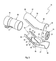
- the collar 22 is at an in FIG. 3 visible inside 23 of the wall 17 is arranged at an opening edge 24 which surrounds the nozzle opening 18. Furthermore, the collar 22 is welded to the wall 17.
- a corresponding weld joint 25 is in FIG. 2 indicated.
- the welded joint 25 can be designed as a closed circumferential weld 26 expediently.
- the weld 26 is located on the inside 23 of the wall 17th
- the exhaust pipe 15 consists in the example shown of a first shell 27 and a second shell 28. Both shells 27, 28 each extend from an inlet end 29 of the exhaust pipe 15 to an outlet end 30 of the exhaust pipe 15.
- the nozzle opening 18 is at the first Shell 27 is formed so that the nozzle 16 is attached exclusively to the first shell 27.
- the injection device 14 also includes the static mixer 13, which is used for this purpose in the region of the outlet end 30 in the exhaust pipe 15.
- the mixer 13 is a separate component with respect to the exhaust pipe 15.
- the mixer 13 has a plurality of turbine blades 31 arranged in the manner of a turbine as well as an annular jacket body 32 which completely encloses the guide blades 31 radially outward in the circumferential direction of the pattern 13.
- On the jacket 32 two diametrically opposed engaging portions 33 are formed, which engage on the respective side in a connecting region 34 between the two shells 27, 28.
- the mixer 13 is fixed to the exhaust pipe 15.
- the two shells 27, 28 are welded together in the respective connecting region 34.
- An associated weld is in Fig. 2 labeled 42. Each such weld seam 42 extends on opposite sides of the exhaust pipe 15 in each case along the respective connecting region 34.
- the exhaust pipe 15 has a first arc 35.
- the nozzle opening 18 is arranged axially aligned with the outlet end 30 of the exhaust pipe 15.
- the nozzle 16 is configured as a straight tube and aligned coaxially with the outlet end 30.
- An in FIG. 1 indicated axial direction 36 thus extends concentrically through the nozzle 16 and in the region of the outlet end 30 through the exhaust pipe 15.
- the injector 10 can now also introduce the reducing agent 11 concentric to this axial direction 36 in the exhaust stream 8.
- the exhaust pipe 15 here also has a second arc 37 and a formed between the first sheet 35 and the second arc 37 straight pipe section 38. At this straight pipe section 38, the nozzle opening 18 is arranged.
- the first arc 35 and the second arc 37 lie in a common longitudinal center plane of the exhaust pipe 15, which in FIG. 1 corresponds to the drawing plane.
- the first sheet 35 and the second sheet 37 have opposite curvatures.
- the second arc 37 a right turn, while the subsequent first arc 35 describes a left turn.
- the first arc 35 and the second arc 37 have substantially the same curvatures in terms of magnitude.
- an entrance-side longitudinal central axis of the exhaust pipe 15, which is present in the inlet end 29, is oriented substantially parallel to an exit-side longitudinal central axis of the exhaust pipe 15, which is present in the outlet end 30.
- the nozzle 16 is arranged on the exhaust pipe 15 so that its longitudinal central axis 36, which may also be referred to below as a nozzle longitudinal center axis 36, is inclined relative to a vertical direction, which is radially to a in Fig. 1 indicated longitudinal center axis 43 which has the exhaust pipe 15 in the region of the nozzle opening 18 and which may also be referred to below as tube longitudinal center axis 43.
- This inclination between the nozzle longitudinal center axis 36 and the tube longitudinal center axis 43 or its vertical direction is approximately 45 ° in the example shown.
- the curvatures of the two sheets 35, 37 may be the same size or be substantially the same size, ie have deviations of at most 20% and preferably of not more than 10% at their radii of curvature.
- the injection device 14 may further comprise a connection pipe 39 which is connected in a suitable manner fixed to the exhaust pipe 15 and which is connectable by means of a clamp 40 to an adjacent component of the exhaust system 7.
- the connecting pipe 29 may be laterally slotted at an end remote from the exhaust pipe 15. A corresponding slot 41 is in FIG. 3 recognizable.
- connection pipe 39 can be connected to the exhaust pipe 15.
- the connection pipe can be 39 axially insert into the inlet end 29 of the exhaust pipe 15 and weld it.
Landscapes
- Engineering & Computer Science (AREA)
- Chemical & Material Sciences (AREA)
- Combustion & Propulsion (AREA)
- Mechanical Engineering (AREA)
- General Engineering & Computer Science (AREA)
- Chemical Kinetics & Catalysis (AREA)
- Health & Medical Sciences (AREA)
- Toxicology (AREA)
- Exhaust Gas After Treatment (AREA)
- Exhaust Silencers (AREA)
Applications Claiming Priority (1)
| Application Number | Priority Date | Filing Date | Title |
|---|---|---|---|
| DE102014215084.1A DE102014215084C5 (de) | 2014-07-31 | 2014-07-31 | Injektionseinrichtung und zugehöriges Herstellungsverfahren |
Publications (3)
| Publication Number | Publication Date |
|---|---|
| EP2980379A1 true EP2980379A1 (fr) | 2016-02-03 |
| EP2980379B1 EP2980379B1 (fr) | 2016-10-05 |
| EP2980379B2 EP2980379B2 (fr) | 2019-05-22 |
Family
ID=53442638
Family Applications (1)
| Application Number | Title | Priority Date | Filing Date |
|---|---|---|---|
| EP15172830.0A Not-in-force EP2980379B2 (fr) | 2014-07-31 | 2015-06-19 | Dispositif d'injection et procede de fabrication associe |
Country Status (3)
| Country | Link |
|---|---|
| US (1) | US10167761B2 (fr) |
| EP (1) | EP2980379B2 (fr) |
| DE (1) | DE102014215084C5 (fr) |
Cited By (8)
| Publication number | Priority date | Publication date | Assignee | Title |
|---|---|---|---|---|
| US9664081B2 (en) | 2007-07-24 | 2017-05-30 | Faurecia Emissions Control Technologies, Germany Gmbh | Assembly and method for introducing a reducing agent into the exhaust pipe of an exhaust system of an internal combustion engine |
| US9714598B2 (en) | 2015-04-30 | 2017-07-25 | Faurecia Emissions Control Technologies, Usa, Llc | Mixer with integrated doser cone |
| US9719397B2 (en) | 2015-04-30 | 2017-08-01 | Faurecia Emissions Control Technologies Usa, Llc | Mixer with integrated doser cone |
| US9726064B2 (en) | 2015-04-30 | 2017-08-08 | Faurecia Emissions Control Technologies, Usa, Llc | Mixer for use in a vehicle exhaust system |
| US9828897B2 (en) | 2015-04-30 | 2017-11-28 | Faurecia Emissions Control Technologies Usa, Llc | Mixer for a vehicle exhaust system |
| US10227907B2 (en) | 2014-06-03 | 2019-03-12 | Faurecia Emissions Control Technologies, Usa, Llc | Mixer and doser cone assembly |
| US10697347B1 (en) | 2019-01-08 | 2020-06-30 | Eberspächer Exhaust Technology GmbH | Mixer for an exhaust system of an internal combustion engine |
| US10933387B2 (en) | 2016-10-21 | 2021-03-02 | Faurecia Emissions Control Technologies, Usa, Llc | Reducing agent mixer |
Families Citing this family (6)
| Publication number | Priority date | Publication date | Assignee | Title |
|---|---|---|---|---|
| JP6424869B2 (ja) * | 2016-09-16 | 2018-11-21 | マツダ株式会社 | エンジンの排気浄化装置 |
| US10787946B2 (en) | 2018-09-19 | 2020-09-29 | Faurecia Emissions Control Technologies, Usa, Llc | Heated dosing mixer |
| SE543916C2 (en) * | 2019-12-11 | 2021-09-21 | Scania Cv Ab | Evaporator module and exhaust aftertreatment system comprising such a module |
| JP2021156226A (ja) * | 2020-03-27 | 2021-10-07 | フタバ産業株式会社 | 排ガス浄化装置 |
| US11441460B2 (en) | 2020-10-26 | 2022-09-13 | Caterpillar Inc. | Vane mixer in engine exhaust system |
| DE102023122361A1 (de) * | 2023-08-22 | 2025-02-27 | Purem GmbH | Anschlusseinheit |
Citations (4)
| Publication number | Priority date | Publication date | Assignee | Title |
|---|---|---|---|---|
| FR1327284A (fr) * | 1962-04-06 | 1963-05-17 | Pot d'échappement | |
| DE202008001547U1 (de) * | 2007-07-24 | 2008-04-10 | Emcon Technologies Germany (Augsburg) Gmbh | Baugruppe zur Einbringung eines Reduktionsmittels in die Abgasleitung einer Abgasanlage einer Verbrennungskraftmaschine |
| DE102007048560A1 (de) * | 2007-10-09 | 2009-04-23 | Audi Ag | Vorrichtung zum Nachbehandeln von Abgasen einer magerlauffähigen Brennkraftmaschine |
| DE102010049018A1 (de) * | 2010-10-21 | 2012-04-26 | Tenneco Gmbh | Stutzen zum Einbringen von Reduktionsmittel |
Family Cites Families (15)
| Publication number | Priority date | Publication date | Assignee | Title |
|---|---|---|---|---|
| US5349817A (en) | 1993-11-12 | 1994-09-27 | Benteler Industries, Inc. | Air gap manifold port flange connection |
| US6279603B1 (en) * | 1998-10-01 | 2001-08-28 | Ambac International | Fluid-cooled injector |
| GB9915939D0 (en) | 1999-07-08 | 1999-09-08 | Johnson Matthey Plc | Improvements in pollution control |
| US6996976B2 (en) * | 2002-04-03 | 2006-02-14 | Cleaire Advanced Emmision Controls | Apparatus and method for mounting a device to a pipe |
| DE202004000200U1 (de) | 2004-01-09 | 2004-04-15 | Heinrich Gillet Gmbh | Gehäuse für Abgasanlagen |
| DE102005052064A1 (de) | 2005-10-28 | 2007-05-31 | J. Eberspächer GmbH & Co. KG | Abgasanlage |
| WO2008034981A1 (fr) | 2006-09-21 | 2008-03-27 | Renault S.A.S | Agencement pour la depollution d'un moteur thermique de vehicule automobile |
| DE102006059507B4 (de) * | 2006-12-14 | 2016-08-25 | Eberspächer Exhaust Technology GmbH & Co. KG | Abgasanlage mit Injektor |
| WO2008121319A2 (fr) * | 2007-03-30 | 2008-10-09 | Continental Automotive Systems Us, Inc. | Unité de fourniture d'agent de réduction pour une réduction catalytique sélective |
| DE202007010324U1 (de) | 2007-07-25 | 2008-11-27 | Heinrich Gillet Gmbh | Vorrichtung zum Nachbehandeln der Abgase von Dieselmotoren |
| DE102008050101A1 (de) * | 2008-10-06 | 2010-04-08 | Volkswagen Ag | Vorrichtung zur Eindosierung eines Mediums in einem Abgasstrom |
| US8240137B2 (en) * | 2009-10-27 | 2012-08-14 | Cummins Filtration Ip, Inc. | Reductant injection and decomposition system |
| US8756921B2 (en) * | 2011-01-10 | 2014-06-24 | Paccar Inc | Reductant delivery device |
| KR101484254B1 (ko) | 2012-10-26 | 2015-01-16 | 현대자동차 주식회사 | 차량의 배기 시스템용 선택적 촉매 환원 장치 |
| JP5977375B2 (ja) * | 2013-01-25 | 2016-08-24 | フタバ産業株式会社 | 排ガス浄化装置 |
-
2014
- 2014-07-31 DE DE102014215084.1A patent/DE102014215084C5/de not_active Expired - Fee Related
-
2015
- 2015-06-19 EP EP15172830.0A patent/EP2980379B2/fr not_active Not-in-force
- 2015-07-29 US US14/812,166 patent/US10167761B2/en active Active
Patent Citations (4)
| Publication number | Priority date | Publication date | Assignee | Title |
|---|---|---|---|---|
| FR1327284A (fr) * | 1962-04-06 | 1963-05-17 | Pot d'échappement | |
| DE202008001547U1 (de) * | 2007-07-24 | 2008-04-10 | Emcon Technologies Germany (Augsburg) Gmbh | Baugruppe zur Einbringung eines Reduktionsmittels in die Abgasleitung einer Abgasanlage einer Verbrennungskraftmaschine |
| DE102007048560A1 (de) * | 2007-10-09 | 2009-04-23 | Audi Ag | Vorrichtung zum Nachbehandeln von Abgasen einer magerlauffähigen Brennkraftmaschine |
| DE102010049018A1 (de) * | 2010-10-21 | 2012-04-26 | Tenneco Gmbh | Stutzen zum Einbringen von Reduktionsmittel |
Cited By (10)
| Publication number | Priority date | Publication date | Assignee | Title |
|---|---|---|---|---|
| US9664081B2 (en) | 2007-07-24 | 2017-05-30 | Faurecia Emissions Control Technologies, Germany Gmbh | Assembly and method for introducing a reducing agent into the exhaust pipe of an exhaust system of an internal combustion engine |
| US10227907B2 (en) | 2014-06-03 | 2019-03-12 | Faurecia Emissions Control Technologies, Usa, Llc | Mixer and doser cone assembly |
| US10294843B2 (en) | 2014-06-03 | 2019-05-21 | Faurecia Emissions Control Technologies, Usa, Llc | Mixer and doser cone assembly |
| US9714598B2 (en) | 2015-04-30 | 2017-07-25 | Faurecia Emissions Control Technologies, Usa, Llc | Mixer with integrated doser cone |
| US9719397B2 (en) | 2015-04-30 | 2017-08-01 | Faurecia Emissions Control Technologies Usa, Llc | Mixer with integrated doser cone |
| US9726064B2 (en) | 2015-04-30 | 2017-08-08 | Faurecia Emissions Control Technologies, Usa, Llc | Mixer for use in a vehicle exhaust system |
| US9828897B2 (en) | 2015-04-30 | 2017-11-28 | Faurecia Emissions Control Technologies Usa, Llc | Mixer for a vehicle exhaust system |
| US10933387B2 (en) | 2016-10-21 | 2021-03-02 | Faurecia Emissions Control Technologies, Usa, Llc | Reducing agent mixer |
| US10697347B1 (en) | 2019-01-08 | 2020-06-30 | Eberspächer Exhaust Technology GmbH | Mixer for an exhaust system of an internal combustion engine |
| EP3680463A1 (fr) * | 2019-01-08 | 2020-07-15 | Eberspächer Exhaust Technology GmbH | Mélangeur pour une installation de gaz d'échappement d'un moteur à combustion interne |
Also Published As
| Publication number | Publication date |
|---|---|
| US20160032808A1 (en) | 2016-02-04 |
| EP2980379B1 (fr) | 2016-10-05 |
| DE102014215084A1 (de) | 2016-02-04 |
| EP2980379B2 (fr) | 2019-05-22 |
| DE102014215084B4 (de) | 2017-08-24 |
| US10167761B2 (en) | 2019-01-01 |
| DE102014215084C5 (de) | 2023-10-05 |
Similar Documents
| Publication | Publication Date | Title |
|---|---|---|
| EP2980379B1 (fr) | Dispositif d'injection et procede de fabrication associe | |
| EP2022956B1 (fr) | Système d'échappement avec dispositif de guidage de l'écoulement | |
| EP2535535B1 (fr) | Mélangeur statique | |
| EP2865861B1 (fr) | Système de catalyseur avec section d'injection | |
| EP2006017B1 (fr) | Dispositif de mélange et/ou d'évaporation et procédé de fabrication correspondant | |
| EP1985356B1 (fr) | Dispositif de mélange et/ou d'évaporation | |
| EP1953359B1 (fr) | Dispositif d'échappement d'un moteur à combustion interne | |
| EP2813679B1 (fr) | Système d'échappement d'un moteur à combustion interne | |
| EP3015672B1 (fr) | Dispositif de traitement de gaz d'échappement | |
| EP2278133A2 (fr) | Dispositif de mélange et/ou d'évaporation | |
| EP2979750A1 (fr) | Mélangeur et dispositif de mélange pour une installation de gaz d'échappement | |
| DE102007048560A1 (de) | Vorrichtung zum Nachbehandeln von Abgasen einer magerlauffähigen Brennkraftmaschine | |
| DE102008029110A1 (de) | Misch- und/oder Verdampfungseinrichtung | |
| DE102010025611A1 (de) | Abgasstrang für ein Kraftfahrzeug | |
| EP3196434B1 (fr) | Scr système de post-traitement de gaz d'échappement | |
| EP2799681B1 (fr) | Composant de ligne d'échappement | |
| EP3549663B1 (fr) | Installation de gaz d'échappement et module mélangeur pour une installation de gaz d'échappement | |
| EP2643569B1 (fr) | Silencieux | |
| DE102012014528A1 (de) | Mehrstufiger Plattenmischer | |
| EP2915973B1 (fr) | Agencement trémie-tube | |
| WO2012035163A1 (fr) | Unité de traitement de gaz d'échappement pour une conduite de recyclage de gaz d'échappement | |
| EP3643898B1 (fr) | Procédé de fabrication d'un dispositif de traitement des gaz d'échappement | |
| EP3549662B1 (fr) | Module mélangeur | |
| EP4613987A1 (fr) | Ensemble support de sonde, en particulier pour un système d'échappement d'un moteur à combustion interne | |
| DE102004024831A1 (de) | Verfahren zum Herstellen einer Flanschanbindung und Abgasstrang-Flanschanbindung |
Legal Events
| Date | Code | Title | Description |
|---|---|---|---|
| PUAI | Public reference made under article 153(3) epc to a published international application that has entered the european phase |
Free format text: ORIGINAL CODE: 0009012 |
|
| 17P | Request for examination filed |
Effective date: 20150619 |
|
| AK | Designated contracting states |
Kind code of ref document: A1 Designated state(s): AL AT BE BG CH CY CZ DE DK EE ES FI FR GB GR HR HU IE IS IT LI LT LU LV MC MK MT NL NO PL PT RO RS SE SI SK SM TR |
|
| AX | Request for extension of the european patent |
Extension state: BA ME |
|
| GRAP | Despatch of communication of intention to grant a patent |
Free format text: ORIGINAL CODE: EPIDOSNIGR1 |
|
| INTG | Intention to grant announced |
Effective date: 20160615 |
|
| GRAS | Grant fee paid |
Free format text: ORIGINAL CODE: EPIDOSNIGR3 |
|
| GRAA | (expected) grant |
Free format text: ORIGINAL CODE: 0009210 |
|
| AK | Designated contracting states |
Kind code of ref document: B1 Designated state(s): AL AT BE BG CH CY CZ DE DK EE ES FI FR GB GR HR HU IE IS IT LI LT LU LV MC MK MT NL NO PL PT RO RS SE SI SK SM TR |
|
| REG | Reference to a national code |
Ref country code: GB Ref legal event code: FG4D Free format text: NOT ENGLISH |
|
| REG | Reference to a national code |
Ref country code: CH Ref legal event code: EP |
|
| REG | Reference to a national code |
Ref country code: AT Ref legal event code: REF Ref document number: 834878 Country of ref document: AT Kind code of ref document: T Effective date: 20161015 |
|
| REG | Reference to a national code |
Ref country code: IE Ref legal event code: FG4D Free format text: LANGUAGE OF EP DOCUMENT: GERMAN |
|
| REG | Reference to a national code |
Ref country code: DE Ref legal event code: R096 Ref document number: 502015000205 Country of ref document: DE |
|
| REG | Reference to a national code |
Ref country code: SE Ref legal event code: TRGR |
|
| REG | Reference to a national code |
Ref country code: NL Ref legal event code: MP Effective date: 20161005 |
|
| REG | Reference to a national code |
Ref country code: LT Ref legal event code: MG4D |
|
| PG25 | Lapsed in a contracting state [announced via postgrant information from national office to epo] |
Ref country code: LV Free format text: LAPSE BECAUSE OF FAILURE TO SUBMIT A TRANSLATION OF THE DESCRIPTION OR TO PAY THE FEE WITHIN THE PRESCRIBED TIME-LIMIT Effective date: 20161005 |
|
| PG25 | Lapsed in a contracting state [announced via postgrant information from national office to epo] |
Ref country code: NO Free format text: LAPSE BECAUSE OF FAILURE TO SUBMIT A TRANSLATION OF THE DESCRIPTION OR TO PAY THE FEE WITHIN THE PRESCRIBED TIME-LIMIT Effective date: 20170105 Ref country code: GR Free format text: LAPSE BECAUSE OF FAILURE TO SUBMIT A TRANSLATION OF THE DESCRIPTION OR TO PAY THE FEE WITHIN THE PRESCRIBED TIME-LIMIT Effective date: 20170106 Ref country code: LT Free format text: LAPSE BECAUSE OF FAILURE TO SUBMIT A TRANSLATION OF THE DESCRIPTION OR TO PAY THE FEE WITHIN THE PRESCRIBED TIME-LIMIT Effective date: 20161005 |
|
| PG25 | Lapsed in a contracting state [announced via postgrant information from national office to epo] |
Ref country code: NL Free format text: LAPSE BECAUSE OF FAILURE TO SUBMIT A TRANSLATION OF THE DESCRIPTION OR TO PAY THE FEE WITHIN THE PRESCRIBED TIME-LIMIT Effective date: 20161005 Ref country code: IS Free format text: LAPSE BECAUSE OF FAILURE TO SUBMIT A TRANSLATION OF THE DESCRIPTION OR TO PAY THE FEE WITHIN THE PRESCRIBED TIME-LIMIT Effective date: 20170205 Ref country code: FI Free format text: LAPSE BECAUSE OF FAILURE TO SUBMIT A TRANSLATION OF THE DESCRIPTION OR TO PAY THE FEE WITHIN THE PRESCRIBED TIME-LIMIT Effective date: 20161005 Ref country code: HR Free format text: LAPSE BECAUSE OF FAILURE TO SUBMIT A TRANSLATION OF THE DESCRIPTION OR TO PAY THE FEE WITHIN THE PRESCRIBED TIME-LIMIT Effective date: 20161005 Ref country code: PL Free format text: LAPSE BECAUSE OF FAILURE TO SUBMIT A TRANSLATION OF THE DESCRIPTION OR TO PAY THE FEE WITHIN THE PRESCRIBED TIME-LIMIT Effective date: 20161005 Ref country code: RS Free format text: LAPSE BECAUSE OF FAILURE TO SUBMIT A TRANSLATION OF THE DESCRIPTION OR TO PAY THE FEE WITHIN THE PRESCRIBED TIME-LIMIT Effective date: 20161005 Ref country code: ES Free format text: LAPSE BECAUSE OF FAILURE TO SUBMIT A TRANSLATION OF THE DESCRIPTION OR TO PAY THE FEE WITHIN THE PRESCRIBED TIME-LIMIT Effective date: 20161005 Ref country code: PT Free format text: LAPSE BECAUSE OF FAILURE TO SUBMIT A TRANSLATION OF THE DESCRIPTION OR TO PAY THE FEE WITHIN THE PRESCRIBED TIME-LIMIT Effective date: 20170206 |
|
| REG | Reference to a national code |
Ref country code: FR Ref legal event code: PLFP Year of fee payment: 3 |
|
| REG | Reference to a national code |
Ref country code: DE Ref legal event code: R026 Ref document number: 502015000205 Country of ref document: DE |
|
| PLBI | Opposition filed |
Free format text: ORIGINAL CODE: 0009260 |
|
| PG25 | Lapsed in a contracting state [announced via postgrant information from national office to epo] |
Ref country code: EE Free format text: LAPSE BECAUSE OF FAILURE TO SUBMIT A TRANSLATION OF THE DESCRIPTION OR TO PAY THE FEE WITHIN THE PRESCRIBED TIME-LIMIT Effective date: 20161005 Ref country code: DK Free format text: LAPSE BECAUSE OF FAILURE TO SUBMIT A TRANSLATION OF THE DESCRIPTION OR TO PAY THE FEE WITHIN THE PRESCRIBED TIME-LIMIT Effective date: 20161005 Ref country code: RO Free format text: LAPSE BECAUSE OF FAILURE TO SUBMIT A TRANSLATION OF THE DESCRIPTION OR TO PAY THE FEE WITHIN THE PRESCRIBED TIME-LIMIT Effective date: 20161005 Ref country code: SK Free format text: LAPSE BECAUSE OF FAILURE TO SUBMIT A TRANSLATION OF THE DESCRIPTION OR TO PAY THE FEE WITHIN THE PRESCRIBED TIME-LIMIT Effective date: 20161005 Ref country code: CZ Free format text: LAPSE BECAUSE OF FAILURE TO SUBMIT A TRANSLATION OF THE DESCRIPTION OR TO PAY THE FEE WITHIN THE PRESCRIBED TIME-LIMIT Effective date: 20161005 |
|
| PLAX | Notice of opposition and request to file observation + time limit sent |
Free format text: ORIGINAL CODE: EPIDOSNOBS2 |
|
| PLBB | Reply of patent proprietor to notice(s) of opposition received |
Free format text: ORIGINAL CODE: EPIDOSNOBS3 |
|
| 26 | Opposition filed |
Opponent name: TENNECO GMBH Effective date: 20170705 |
|
| PG25 | Lapsed in a contracting state [announced via postgrant information from national office to epo] |
Ref country code: SM Free format text: LAPSE BECAUSE OF FAILURE TO SUBMIT A TRANSLATION OF THE DESCRIPTION OR TO PAY THE FEE WITHIN THE PRESCRIBED TIME-LIMIT Effective date: 20161005 Ref country code: BG Free format text: LAPSE BECAUSE OF FAILURE TO SUBMIT A TRANSLATION OF THE DESCRIPTION OR TO PAY THE FEE WITHIN THE PRESCRIBED TIME-LIMIT Effective date: 20170105 |
|
| PG25 | Lapsed in a contracting state [announced via postgrant information from national office to epo] |
Ref country code: SI Free format text: LAPSE BECAUSE OF FAILURE TO SUBMIT A TRANSLATION OF THE DESCRIPTION OR TO PAY THE FEE WITHIN THE PRESCRIBED TIME-LIMIT Effective date: 20161005 |
|
| PG25 | Lapsed in a contracting state [announced via postgrant information from national office to epo] |
Ref country code: MC Free format text: LAPSE BECAUSE OF FAILURE TO SUBMIT A TRANSLATION OF THE DESCRIPTION OR TO PAY THE FEE WITHIN THE PRESCRIBED TIME-LIMIT Effective date: 20161005 |
|
| REG | Reference to a national code |
Ref country code: IE Ref legal event code: MM4A |
|
| PG25 | Lapsed in a contracting state [announced via postgrant information from national office to epo] |
Ref country code: LU Free format text: LAPSE BECAUSE OF NON-PAYMENT OF DUE FEES Effective date: 20170619 Ref country code: IE Free format text: LAPSE BECAUSE OF NON-PAYMENT OF DUE FEES Effective date: 20170619 |
|
| REG | Reference to a national code |
Ref country code: BE Ref legal event code: MM Effective date: 20170630 |
|
| REG | Reference to a national code |
Ref country code: FR Ref legal event code: PLFP Year of fee payment: 4 |
|
| REG | Reference to a national code |
Ref country code: DE Ref legal event code: R082 Ref document number: 502015000205 Country of ref document: DE Representative=s name: RUTTENSPERGER LACHNIT TROSSIN GOMOLL, PATENT- , DE Ref country code: DE Ref legal event code: R082 Ref document number: 502015000205 Country of ref document: DE Representative=s name: RUTTENSPERGER LACHNIT TROSSIN GOMOLL PATENT- U, DE |
|
| PG25 | Lapsed in a contracting state [announced via postgrant information from national office to epo] |
Ref country code: BE Free format text: LAPSE BECAUSE OF NON-PAYMENT OF DUE FEES Effective date: 20170630 |
|
| PGFP | Annual fee paid to national office [announced via postgrant information from national office to epo] |
Ref country code: IT Payment date: 20180630 Year of fee payment: 4 |
|
| PG25 | Lapsed in a contracting state [announced via postgrant information from national office to epo] |
Ref country code: MT Free format text: LAPSE BECAUSE OF FAILURE TO SUBMIT A TRANSLATION OF THE DESCRIPTION OR TO PAY THE FEE WITHIN THE PRESCRIBED TIME-LIMIT Effective date: 20161005 |
|
| APAH | Appeal reference modified |
Free format text: ORIGINAL CODE: EPIDOSCREFNO |
|
| APBM | Appeal reference recorded |
Free format text: ORIGINAL CODE: EPIDOSNREFNO |
|
| APBP | Date of receipt of notice of appeal recorded |
Free format text: ORIGINAL CODE: EPIDOSNNOA2O |
|
| REG | Reference to a national code |
Ref country code: CH Ref legal event code: PL |
|
| APBU | Appeal procedure closed |
Free format text: ORIGINAL CODE: EPIDOSNNOA9O |
|
| PUAH | Patent maintained in amended form |
Free format text: ORIGINAL CODE: 0009272 |
|
| STAA | Information on the status of an ep patent application or granted ep patent |
Free format text: STATUS: PATENT MAINTAINED AS AMENDED |
|
| PG25 | Lapsed in a contracting state [announced via postgrant information from national office to epo] |
Ref country code: CH Free format text: LAPSE BECAUSE OF NON-PAYMENT OF DUE FEES Effective date: 20180630 Ref country code: LI Free format text: LAPSE BECAUSE OF NON-PAYMENT OF DUE FEES Effective date: 20180630 |
|
| 27A | Patent maintained in amended form |
Effective date: 20190522 |
|
| AK | Designated contracting states |
Kind code of ref document: B2 Designated state(s): AL AT BE BG CH CY CZ DE DK EE ES FI FR GB GR HR HU IE IS IT LI LT LU LV MC MK MT NL NO PL PT RO RS SE SI SK SM TR |
|
| REG | Reference to a national code |
Ref country code: DE Ref legal event code: R102 Ref document number: 502015000205 Country of ref document: DE |
|
| REG | Reference to a national code |
Ref country code: SE Ref legal event code: RPEO |
|
| PG25 | Lapsed in a contracting state [announced via postgrant information from national office to epo] |
Ref country code: HU Free format text: LAPSE BECAUSE OF FAILURE TO SUBMIT A TRANSLATION OF THE DESCRIPTION OR TO PAY THE FEE WITHIN THE PRESCRIBED TIME-LIMIT; INVALID AB INITIO Effective date: 20150619 |
|
| PG25 | Lapsed in a contracting state [announced via postgrant information from national office to epo] |
Ref country code: CY Free format text: LAPSE BECAUSE OF FAILURE TO SUBMIT A TRANSLATION OF THE DESCRIPTION OR TO PAY THE FEE WITHIN THE PRESCRIBED TIME-LIMIT Effective date: 20161005 |
|
| PG25 | Lapsed in a contracting state [announced via postgrant information from national office to epo] |
Ref country code: MK Free format text: LAPSE BECAUSE OF FAILURE TO SUBMIT A TRANSLATION OF THE DESCRIPTION OR TO PAY THE FEE WITHIN THE PRESCRIBED TIME-LIMIT Effective date: 20161005 |
|
| PG25 | Lapsed in a contracting state [announced via postgrant information from national office to epo] |
Ref country code: TR Free format text: LAPSE BECAUSE OF FAILURE TO SUBMIT A TRANSLATION OF THE DESCRIPTION OR TO PAY THE FEE WITHIN THE PRESCRIBED TIME-LIMIT Effective date: 20161005 |
|
| PG25 | Lapsed in a contracting state [announced via postgrant information from national office to epo] |
Ref country code: IT Free format text: LAPSE BECAUSE OF NON-PAYMENT OF DUE FEES Effective date: 20190619 |
|
| PG25 | Lapsed in a contracting state [announced via postgrant information from national office to epo] |
Ref country code: AL Free format text: LAPSE BECAUSE OF FAILURE TO SUBMIT A TRANSLATION OF THE DESCRIPTION OR TO PAY THE FEE WITHIN THE PRESCRIBED TIME-LIMIT Effective date: 20161005 |
|
| REG | Reference to a national code |
Ref country code: DE Ref legal event code: R082 Ref document number: 502015000205 Country of ref document: DE Representative=s name: RUTTENSPERGER LACHNIT TROSSIN GOMOLL, PATENT- , DE Ref country code: DE Ref legal event code: R081 Ref document number: 502015000205 Country of ref document: DE Owner name: PUREM GMBH, DE Free format text: FORMER OWNER: EBERSPAECHER EXHAUST TECHNOLOGY GMBH & CO. KG, 66539 NEUNKIRCHEN, DE |
|
| REG | Reference to a national code |
Ref country code: AT Ref legal event code: MM01 Ref document number: 834878 Country of ref document: AT Kind code of ref document: T Effective date: 20200619 |
|
| REG | Reference to a national code |
Ref country code: GB Ref legal event code: 732E Free format text: REGISTERED BETWEEN 20210902 AND 20210908 |
|
| PG25 | Lapsed in a contracting state [announced via postgrant information from national office to epo] |
Ref country code: AT Free format text: LAPSE BECAUSE OF NON-PAYMENT OF DUE FEES Effective date: 20200619 |
|
| PGFP | Annual fee paid to national office [announced via postgrant information from national office to epo] |
Ref country code: GB Payment date: 20240620 Year of fee payment: 10 |
|
| PGFP | Annual fee paid to national office [announced via postgrant information from national office to epo] |
Ref country code: DE Payment date: 20240617 Year of fee payment: 10 |
|
| PGFP | Annual fee paid to national office [announced via postgrant information from national office to epo] |
Ref country code: FR Payment date: 20240621 Year of fee payment: 10 |
|
| PGFP | Annual fee paid to national office [announced via postgrant information from national office to epo] |
Ref country code: SE Payment date: 20240620 Year of fee payment: 10 |
|
| REG | Reference to a national code |
Ref country code: DE Ref legal event code: R119 Ref document number: 502015000205 Country of ref document: DE |
|
| REG | Reference to a national code |
Ref country code: SE Ref legal event code: EUG |
|
| GBPC | Gb: european patent ceased through non-payment of renewal fee |
Effective date: 20250619 |
|
| PG25 | Lapsed in a contracting state [announced via postgrant information from national office to epo] |
Ref country code: GB Free format text: LAPSE BECAUSE OF NON-PAYMENT OF DUE FEES Effective date: 20250619 |
|
| PG25 | Lapsed in a contracting state [announced via postgrant information from national office to epo] |
Ref country code: DE Free format text: LAPSE BECAUSE OF NON-PAYMENT OF DUE FEES Effective date: 20260101 |
|
| PG25 | Lapsed in a contracting state [announced via postgrant information from national office to epo] |
Ref country code: FR Free format text: LAPSE BECAUSE OF NON-PAYMENT OF DUE FEES Effective date: 20250630 |