EP2980384B1 - Dispositif de refroidissement d'air d'admission - Google Patents
Dispositif de refroidissement d'air d'admission Download PDFInfo
- Publication number
- EP2980384B1 EP2980384B1 EP14775523.5A EP14775523A EP2980384B1 EP 2980384 B1 EP2980384 B1 EP 2980384B1 EP 14775523 A EP14775523 A EP 14775523A EP 2980384 B1 EP2980384 B1 EP 2980384B1
- Authority
- EP
- European Patent Office
- Prior art keywords
- intake
- water
- air
- water conduit
- conduit pipes
- Prior art date
- Legal status (The legal status is an assumption and is not a legal conclusion. Google has not performed a legal analysis and makes no representation as to the accuracy of the status listed.)
- Active
Links
Images



Classifications
-
- F—MECHANICAL ENGINEERING; LIGHTING; HEATING; WEAPONS; BLASTING
- F02—COMBUSTION ENGINES; HOT-GAS OR COMBUSTION-PRODUCT ENGINE PLANTS
- F02C—GAS-TURBINE PLANTS; AIR INTAKES FOR JET-PROPULSION PLANTS; CONTROLLING FUEL SUPPLY IN AIR-BREATHING JET-PROPULSION PLANTS
- F02C7/00—Features, components parts, details or accessories, not provided for in, or of interest apart form groups F02C1/00 - F02C6/00; Air intakes for jet-propulsion plants
- F02C7/12—Cooling of plants
- F02C7/14—Cooling of plants of fluids in the plant, e.g. lubricant or fuel
- F02C7/141—Cooling of plants of fluids in the plant, e.g. lubricant or fuel of working fluid
- F02C7/143—Cooling of plants of fluids in the plant, e.g. lubricant or fuel of working fluid before or between the compressor stages
- F02C7/1435—Cooling of plants of fluids in the plant, e.g. lubricant or fuel of working fluid before or between the compressor stages by water injection
-
- F—MECHANICAL ENGINEERING; LIGHTING; HEATING; WEAPONS; BLASTING
- F01—MACHINES OR ENGINES IN GENERAL; ENGINE PLANTS IN GENERAL; STEAM ENGINES
- F01D—NON-POSITIVE DISPLACEMENT MACHINES OR ENGINES, e.g. STEAM TURBINES
- F01D25/00—Component parts, details, or accessories, not provided for in, or of interest apart from, other groups
- F01D25/08—Cooling; Heating; Heat-insulation
- F01D25/12—Cooling
-
- F—MECHANICAL ENGINEERING; LIGHTING; HEATING; WEAPONS; BLASTING
- F01—MACHINES OR ENGINES IN GENERAL; ENGINE PLANTS IN GENERAL; STEAM ENGINES
- F01D—NON-POSITIVE DISPLACEMENT MACHINES OR ENGINES, e.g. STEAM TURBINES
- F01D9/00—Stators
- F01D9/02—Nozzles; Nozzle boxes; Stator blades; Guide conduits, e.g. individual nozzles
- F01D9/04—Nozzles; Nozzle boxes; Stator blades; Guide conduits, e.g. individual nozzles forming ring or sector
- F01D9/041—Nozzles; Nozzle boxes; Stator blades; Guide conduits, e.g. individual nozzles forming ring or sector using blades
-
- F—MECHANICAL ENGINEERING; LIGHTING; HEATING; WEAPONS; BLASTING
- F02—COMBUSTION ENGINES; HOT-GAS OR COMBUSTION-PRODUCT ENGINE PLANTS
- F02C—GAS-TURBINE PLANTS; AIR INTAKES FOR JET-PROPULSION PLANTS; CONTROLLING FUEL SUPPLY IN AIR-BREATHING JET-PROPULSION PLANTS
- F02C3/00—Gas-turbine plants characterised by the use of combustion products as the working fluid
- F02C3/20—Gas-turbine plants characterised by the use of combustion products as the working fluid using a special fuel, oxidant, or dilution fluid to generate the combustion products
- F02C3/30—Adding water, steam or other fluids for influencing combustion, e.g. to obtain cleaner exhaust gases
-
- F—MECHANICAL ENGINEERING; LIGHTING; HEATING; WEAPONS; BLASTING
- F02—COMBUSTION ENGINES; HOT-GAS OR COMBUSTION-PRODUCT ENGINE PLANTS
- F02C—GAS-TURBINE PLANTS; AIR INTAKES FOR JET-PROPULSION PLANTS; CONTROLLING FUEL SUPPLY IN AIR-BREATHING JET-PROPULSION PLANTS
- F02C7/00—Features, components parts, details or accessories, not provided for in, or of interest apart form groups F02C1/00 - F02C6/00; Air intakes for jet-propulsion plants
- F02C7/04—Air intakes for gas-turbine plants or jet-propulsion plants
-
- F—MECHANICAL ENGINEERING; LIGHTING; HEATING; WEAPONS; BLASTING
- F02—COMBUSTION ENGINES; HOT-GAS OR COMBUSTION-PRODUCT ENGINE PLANTS
- F02C—GAS-TURBINE PLANTS; AIR INTAKES FOR JET-PROPULSION PLANTS; CONTROLLING FUEL SUPPLY IN AIR-BREATHING JET-PROPULSION PLANTS
- F02C9/00—Controlling gas-turbine plants; Controlling fuel supply in air- breathing jet-propulsion plants
- F02C9/16—Control of working fluid flow
-
- F—MECHANICAL ENGINEERING; LIGHTING; HEATING; WEAPONS; BLASTING
- F04—POSITIVE - DISPLACEMENT MACHINES FOR LIQUIDS; PUMPS FOR LIQUIDS OR ELASTIC FLUIDS
- F04B—POSITIVE-DISPLACEMENT MACHINES FOR LIQUIDS; PUMPS
- F04B17/00—Pumps characterised by combination with, or adaptation to, specific driving engines or motors
- F04B17/03—Pumps characterised by combination with, or adaptation to, specific driving engines or motors driven by electric motors
-
- F—MECHANICAL ENGINEERING; LIGHTING; HEATING; WEAPONS; BLASTING
- F04—POSITIVE - DISPLACEMENT MACHINES FOR LIQUIDS; PUMPS FOR LIQUIDS OR ELASTIC FLUIDS
- F04B—POSITIVE-DISPLACEMENT MACHINES FOR LIQUIDS; PUMPS
- F04B49/00—Control, e.g. of pump delivery, or pump pressure of, or safety measures for, machines, pumps, or pumping installations, not otherwise provided for, or of interest apart from, groups F04B1/00 - F04B47/00
- F04B49/06—Control using electricity
-
- F—MECHANICAL ENGINEERING; LIGHTING; HEATING; WEAPONS; BLASTING
- F04—POSITIVE - DISPLACEMENT MACHINES FOR LIQUIDS; PUMPS FOR LIQUIDS OR ELASTIC FLUIDS
- F04B—POSITIVE-DISPLACEMENT MACHINES FOR LIQUIDS; PUMPS
- F04B2201/00—Pump parameters
- F04B2201/12—Parameters of driving or driven means
- F04B2201/1201—Rotational speed of the axis
-
- F—MECHANICAL ENGINEERING; LIGHTING; HEATING; WEAPONS; BLASTING
- F04—POSITIVE - DISPLACEMENT MACHINES FOR LIQUIDS; PUMPS FOR LIQUIDS OR ELASTIC FLUIDS
- F04B—POSITIVE-DISPLACEMENT MACHINES FOR LIQUIDS; PUMPS
- F04B2203/00—Motor parameters
- F04B2203/02—Motor parameters of rotating electric motors
- F04B2203/0209—Rotational speed
-
- F—MECHANICAL ENGINEERING; LIGHTING; HEATING; WEAPONS; BLASTING
- F04—POSITIVE - DISPLACEMENT MACHINES FOR LIQUIDS; PUMPS FOR LIQUIDS OR ELASTIC FLUIDS
- F04B—POSITIVE-DISPLACEMENT MACHINES FOR LIQUIDS; PUMPS
- F04B2205/00—Fluid parameters
- F04B2205/09—Flow through the pump
-
- F—MECHANICAL ENGINEERING; LIGHTING; HEATING; WEAPONS; BLASTING
- F05—INDEXING SCHEMES RELATING TO ENGINES OR PUMPS IN VARIOUS SUBCLASSES OF CLASSES F01-F04
- F05D—INDEXING SCHEME FOR ASPECTS RELATING TO NON-POSITIVE-DISPLACEMENT MACHINES OR ENGINES, GAS-TURBINES OR JET-PROPULSION PLANTS
- F05D2210/00—Working fluids
- F05D2210/10—Kind or type
- F05D2210/12—Kind or type gaseous, i.e. compressible
-
- F—MECHANICAL ENGINEERING; LIGHTING; HEATING; WEAPONS; BLASTING
- F05—INDEXING SCHEMES RELATING TO ENGINES OR PUMPS IN VARIOUS SUBCLASSES OF CLASSES F01-F04
- F05D—INDEXING SCHEME FOR ASPECTS RELATING TO NON-POSITIVE-DISPLACEMENT MACHINES OR ENGINES, GAS-TURBINES OR JET-PROPULSION PLANTS
- F05D2220/00—Application
- F05D2220/30—Application in turbines
- F05D2220/32—Application in turbines in gas turbines
-
- F—MECHANICAL ENGINEERING; LIGHTING; HEATING; WEAPONS; BLASTING
- F05—INDEXING SCHEMES RELATING TO ENGINES OR PUMPS IN VARIOUS SUBCLASSES OF CLASSES F01-F04
- F05D—INDEXING SCHEME FOR ASPECTS RELATING TO NON-POSITIVE-DISPLACEMENT MACHINES OR ENGINES, GAS-TURBINES OR JET-PROPULSION PLANTS
- F05D2260/00—Function
- F05D2260/20—Heat transfer, e.g. cooling
- F05D2260/212—Heat transfer, e.g. cooling by water injection
-
- F—MECHANICAL ENGINEERING; LIGHTING; HEATING; WEAPONS; BLASTING
- F05—INDEXING SCHEMES RELATING TO ENGINES OR PUMPS IN VARIOUS SUBCLASSES OF CLASSES F01-F04
- F05D—INDEXING SCHEME FOR ASPECTS RELATING TO NON-POSITIVE-DISPLACEMENT MACHINES OR ENGINES, GAS-TURBINES OR JET-PROPULSION PLANTS
- F05D2270/00—Control
- F05D2270/30—Control parameters, e.g. input parameters
- F05D2270/311—Air humidity
Definitions
- the present invention relates to an intake-air cooling device which cools intake air introduced into a compressor of a gas turbine.
- a gas turbine for power generation including a compressor, a combustor, and a turbine
- the output of the turbine is affected by the temperature of intake air suctioned into the compressor.
- the temperature of intake air suctioned into the compressor For instance, in summer, when the ambient temperature is high, the density of the intake air decreases and the mass flow rate decreases, which results in a decrease in the output of the turbine.
- an intake-air cooling device which sprays coolant water to the intake air having a high temperature and cools the intake air by utilizing the evaporative latent heat of the water.
- JP 2011-111944 A discloses an intake-air cooling device which includes a plurality of cooling-medium supply systems to adjust the amount of cooling medium which is to be sprayed to intake air and vaporizes a cooling medium efficiently so as to prevent over-fogging by switching each cooling-medium supply system between on and off in accordance with the atmospheric conditions.
- JP 2001-234755 A discloses an intake-air cooling device where a plurality of concentric water conduit pipes are arranged and a plurality of nozzles are respectively equally distributed along the length of the annular water conduit pipes.
- WO 2004/111413 A1 discloses an intake-air cooling device with a plurality of nozzles arranged in linear conduit pipes which are moreover branched from header pipes so as to be parallel to each other. A different pump is used for different nozzle arrangements,
- US 2005/0279101 A1 discloses a further intake-air cooling device with water conduit pipes that are either arranged radially or circumferentially. A single pump is used for a segmented supply of water.
- Each cooling-medium supply system includes a pump for supplying a cooling medium from a tank and a water conduit pipe for guiding the cooling medium supplied from the pump to injection nozzles. Due to unevenness in the pressure distribution inside the water conduit pipe during introduction of the cooling medium from the pump to the water conduit pipe, variation is caused in the mist spray from the injection nozzles disposed on the water conduit pipe.
- An object of the invention is to provide a novel and improved intake-air cooling device capable of uniformly spraying water even during partial operation.
- the present invention provides an intake-air cooling device as defined by claim 1 or claim 2.
- the present invention is an intake-air cooling device disposed on a rear-stage side of a pre-filter disposed on an intake-air inlet side of an intake-air duct for guiding intake air taken in from an intake-air inlet to a compressor, for cooling the intake air by spraying water to the intake air.
- the intake-air cooling device includes: a plurality of nozzles configured to spray the water to the intake air; a plurality of water conduit pipes including the plurality of nozzles arranged in an axial direction of the water conduit pipes; and a plurality of supply pumps configured to supply the water to corresponding one of the plurality of water conduit pipes.
- Each of the plurality of water conduit pipes is an endless member having a different perimeter.
- the nozzles are disposed in an endless fashion, variation of the in-pipe pressure is reduced even in partial operation of the intake-air cooling device, which makes it possible to spray water to the intake air uniformly.
- the intake-air cooling efficiency is improved.
- the plurality of nozzles are arranged to have a distribution in which a density increases from a portion of the water conduit pipes connected to the supply pumps toward a portion opposite to the portion.
- the nozzles are disposed less densely at a portion where the in-pipe pressure is high and more densely at a portion where the in-pipe pressure is low.
- variation of the amount of water sprayed per unit area is reduced, which makes it possible to spray a cooling medium to the intake air uniformly.
- the water conduit pipes are divided intermittently, and the water is supplied to each divided section of the water conduit pipes from the supply pumps.
- the supply pumps may be variable-speed pumps capable of adjusting a flow rate of the water through inverter control.
- the supply pumps may be configured to adjust the flow rate of the water on the basis of at least one of a temperature of the intake air, a humidity of the intake air, an opening degree of inlet guide vanes of the compressor, and a load of a gas turbine.
- FIG. 1 is a schematic configuration diagram of an intake-air cooling device according to one embodiment of the present invention.
- an intake-air cooling device 100 of the present embodiment includes a plurality of nozzles 102a, 102b, 102c for spraying water to intake air, a plurality of water conduit pipes 104a, 104b, 104c in which the plurality of nozzles 102a, 102b, 102c is disposed in the axial direction of the pipes, and a plurality of supply pumps 106a, 106b, 106c for supplying water to the respective water conduit pipes 104a, 104b, 104c.
- intake air refers to air taken in from an intake-air inlet of an intake-air duct described below to be introduced into a compressor.
- Water supplied from the supply pumps 106a, 106b, 106c is respectively introduced to the nozzles 102a, 102b, 102c via the respective water conduit pipes 104a, 104b, 104c. That is, each of the supply pumps 106a, 106b, 106c has an independent water supply system.
- the water conduit pipes 104a, 104b, 104c respectively include nozzle arrangement parts 103a, 103b, 103c on which the nozzles 102a, 102b, 102c are disposed in the axial direction of the pipes, and introduction parts 105a, 105b, 105c for introducing water supplied from the supply pumps 106a, 106b, 106c to the nozzle arrangement parts 103a, 103b, 103c.
- the nozzles 102a, 102b, 102c are disposed concentrically in an endless fashion. Specifically, as illustrated in FIG.
- the nozzle arrangement parts 103a, 103b, 103c are endless members having perimeters varied among the water conduit pipes 104a, 104b, 104c, and the nozzle arrangement parts 103a, 103b, 103c are disposed concentrically.
- the nozzles 102a, 102b, 102c are disposed concentrically and in an endless fashion.
- variation in the in-pipe pressure of the water conduit pipes 104a, 104b, 104c is reduced.
- the intake-air cooling device 100 is partially operated, it is possible to spray water to the intake air uniformly, which improves the intake-air cooling efficiency.
- FIG. 2 is a block diagram showing a configuration of a gas turbine plant including the intake-air cooling device according to one embodiment of the present invention.
- a gas turbine plant 10 serving as a power generation plant includes an intake-air duct 12, a compressor 14, a combustor 16, a gas turbine 18, and a generator 20. Further, the gas turbine plant 10 includes the intake-air cooling device 100 for cooling intake air of the gas turbine 18.
- the intake-air duct 12 guides the intake-air (ambient air: air) taken in from an intake-air inlet 22 to the compressor 14.
- the compressor 14 compresses the intake air supplied via the intake-air duct 12.
- An inlet guide vane (IGV) 15 is disposed on the inlet of the compressor 14.
- the IGV serves to fluctuate the opening degree to adjust the amount of air for combustion to be suctioned.
- the opening degree of the IGV 15 is adjusted by a control part 110 in accordance with the output of the gas turbine 18, which is the load of the gas turbine 18. For instance, during partial-load operation, the angle of the IGV 15 with respect to the axial direction of the gas turbine 18 is increased, and control is performed to reduce the intake-air flow rate. Further, in the present embodiment, the control part 110 adjusts the flow rate of the water supplied from the supply pump 106 included in the intake-air cooling device 100, on the basis of the IGV opening degree of the compressor 14 or the load of the gas turbine 18.
- the combustor 16 combusts fuel using the intake air supplied from the compressor 14.
- the gas turbine 18 is rotated by combustion gas supplied from the combustor 16.
- the generator 20 generates electric power from rotation of the gas turbine 18.
- the intake-air duct 12 includes a horizontal duct 12a, a curved duct 12b, and a vertical duct 12c from the upstream side in this order.
- a manifold part 12d is disposed at the downstream side of the vertical duct 12c for guiding the intake air to the compressor 14 while rectifying the flow of the intake air.
- the manifold part 12d extends downward via the vertical duct 12c bending downward in the vertical direction with respect to the horizontal duct 12a.
- the intake-air cooling device 100 of the present embodiment may be applied also to an intake-air duct configured to have a different shape such as a straight shape.
- a pre-filter 24 for removing relatively large dust or the like from intake air taken in from the intake-air inlet 22 is disposed at the intake-air inlet side of the intake-air duct 12. Further, at the rear stage of the pre-filter 24 inside the intake-air duct 12 (horizontal duct 12a), the intake-air cooling device 100 for spraying water to intake air that has passed through the pre-filter 24 to cool the intake air is disposed. That is, the intake-air cooling device 100 has a function to spray water to intake air which is to be introduced into the compressor 14 to cool the intake air.
- the intake-air cooling device 100 includes the plurality of nozzles 102 for spraying water to intake air. Water is supplied to the nozzles 102 from a tank 108 via the supply pumps 106 (106a, 106b, 106c) provided respectively for the plurality of water conduit pipes 104 (104a, 104b, 104c).
- variable-speed pumps capable of adjusting the flow rate of water through inverter control are used as the supply pumps 106 (106a, 106b, 106c) to adjust the amount of spray from the respective nozzles 102 (102a, 102b, 102c) more precisely, after reducing the unevenness in the in-pipe pressure of the water conduit pipes 104 (104a, 104b, 104c).
- the supply pumps 106 make the amount of water injection variable by the control part 110, on the basis of at least one of a temperature of the intake air, a humidity of the intake air, an IGV degree of the compressor 14, and the load of the gas turbine 18.
- the supply pumps 106 introduce water to the water conduit pipes 104 so that the flow rate becomes more precise on the basis of the above-described varying factors. As a result, the intake air is cooled without causing over-fogging.
- the nozzle arrangement parts 103a, 103b, 103c (see FIG. 1 ) of the water conduit pipes 104 are endless members.
- the supply pumps 106 being variable-speed pumps, it is possible to adjust the amount of spray from the nozzles more precisely after reducing the unevenness in the in-pipe pressure by adjusting the flow rate of water to be sprayed and the number of pumps to be operated.
- a silencer 40 for restricting vibration including sound that is generated during intake of air is disposed at the downstream side of the intake-air cooling device 100.
- a filter 42 for removing, for instance, impure substances contained in the intake air introduced via the vertical duct 12c and a bolt or the like dropped during, e.g., work inside the intake-air duct is disposed at the inlet side of the manifold part 12d connected to the vertical duct 12c of the intake-air duct 12.
- the nozzles 102a, 102b, 102c are disposed in an endless fashion via the nozzle arrangement parts 103a, 103b, 103c of the water conduit pipes 104.
- variation in the in-pipe pressure of the water conduit pipes 104 is reduced even during partial operation of the intake-air cooling device 100.
- the flow rate of water injection is adjustable in accordance with the IGV opening degree of the compressor 14, the load of the gas turbine, or the temperature or humidity of the intake air, it is possible to optimize water spray to intake air more precisely under a condition where the amount of water is not the maximum both in the vertical and horizontal directions, i.e., during partial load or partial cooling.
- FIG. 3 is a schematic configuration diagram of an intake-air cooling device according to another embodiment of the present invention.
- an intake-air cooling device 200 of the present embodiment includes a plurality of nozzles 202a, 202b, 202c for spraying water to intake air, a plurality of water conduit pipes 204a, 204b, 204c on which the plurality of nozzles 202a, 202b, 202c is disposed in the axial direction of the pipes, and a plurality of supply pumps 206a, 206b, 206c for supplying water to the respective water conduit pipes 204a, 204b, 204c.
- Water supplied from the supply pumps 206a, 206b, 206c is respectively introduced to the nozzles 202a, 202b, 202c via the respective water conduit pipes 204a, 204b, 204c. That is, each of the supply pumps 206a, 206b, 206c has an independent water supply system.
- the water conduit pipes 204a, 204b, 204c respectively include nozzle arrangement parts 203a, 203b, 203c on which the nozzles 202a, 202b, 202c are respectively disposed, and introduction parts 205a, 205b, 205c for introducing water supplied from the supply pumps 206a, 206b, 206c to the above nozzle arrangement parts 203a, 203b, 203c.
- the nozzle arrangement parts 203a, 203b, 203c are endless members having perimeters varied among the water conduit pipes 20a, 204b, 204c, and the nozzle arrangement parts 203a, 203b, 103c are disposed concentrically.
- the arrangement of the nozzles 202a, 202b, 202c is different from that of the first embodiment. Specifically, as illustrated in FIG. 3 , the nozzles 202a, 202b, 202c are arranged in an endless fashion to have such a distribution that the density increases from a portion connecting the nozzle arrangement parts 203a, 203b, 203c and the introduction parts 205a, 205b, 205c toward a portion that is opposite to that portion.
- the nozzles 202a, 202b, 202c at a portion in the vicinity of the supply pumps 206a, 206b, 206c having a high in-pipe pressure are arranged to be less dense, while the nozzles 202a, 202b, 202c at a portion opposite to that portion having a low in-pipe pressure are arranged to be dense.
- Arranging the nozzles 202a, 202b, 202c as described above reduces variation of the amount of water sprayed per unit area, which makes it possible to spray water to intake air uniformly. Specifically, it is possible to make the amount of water sprayed per unit area more uniform between a portion in the vicinity of the supply pumps 206a, 206b, 206c having a high in-pipe pressure and a portion opposite to that portion having a low in-pipe pressure. As a result, variation of water sprayed to the intake air is reduced, and it is possible to improve the intake-air cooling efficiency.
- variable-speed pumps capable of adjusting the flow rate of water through inverter control are used as the supply pumps 206 (206a, 206b, 206c) to adjust the amount of spray from the respective nozzles 202a, 202b, 202c more precisely after reducing the unevenness in the in-pipe pressure of the water conduit pipes 204a, 204b, 204c.
- the supply pumps 206 make the amount of water injection variable on the basis of at least one of a temperature of the intake air, a humidity of the intake air, an IGV degree of the compressor 14, and the load of the gas turbine 18.
- the supply pumps 206 being variable-speed pumps, it is possible to adjust the amount of spray from the nozzles more precisely after reducing the unevenness in the in-pipe pressure by adjusting the flow rate of water to be sprayed and the number of pumps to be operated.
- FIG. 4 is a schematic configuration diagram of an intake-air cooling device according to the another embodiment of the present invention.
- an intake-air cooling device 300 of the present embodiment includes a plurality of nozzles 302a, 302b, 302c for spraying water to intake air, a plurality of water conduit pipes 304a, 304b, 304c on which the plurality of nozzles 302a, 302b, 302c is disposed in the axial direction of the pipes, and a plurality of supply pumps 306a, 306b, 306c for respectively supplying water to the water conduit pipes 304a, 304b, 304c.
- Water supplied from the supply pumps 306a, 306b, 306c is respectively introduced to the nozzles 302a, 302b, 302c via the respective water conduit pipes 304a, 304b, 304c. That is, each of the supply pumps 306a, 306b, 306c has an independent water supply system.
- the water conduit pipes 304a, 304b, 304c respectively include nozzle arrangement parts 303a1 to 303a4, 303b1 to 303b4, 303cl to 303c4 on which the respective nozzles 302a, 302b, 302c are disposed, and introduction parts 305a, 305b, 305c for introducing water supplied from the supply pumps 306a, 306b, 306c to the above nozzle arrangement parts 303a1 to 303a4, 303b1 to 303b4, 303c1 to 303c4.
- the nozzle arrangement parts 303a1 to 303a4, 303b1 to 303b4, 303c1 to 303c4 are endless members having perimeters varied among the water conduit pipes 304a, 304b, 304c, and the nozzle arrangement parts 303a1 to 303a4, 303b1 to 303b4, 303c1 to 303c4 are disposed concentrically.
- the present embodiment is different from the first embodiment in the configuration of the nozzle arrangement parts 303a1 to 303a4, 303b1 to 303b4, 303c1 to 303c4 of the water conduit pipes 304a, 304b, 304c.
- the nozzle arrangement parts 303a1 to 303a4, 303b1 to 303b4, 303cl to 303c4 are divided intermittently, and water is supplied to each divided section of the nozzle arrangement parts 303a1 to 303a4, 303b1 to 303b4, 303c1 to 303c4 from the supply pumps 306a, 306b, 306c.
- the nozzle arrangement parts 303al to 303a4, 303b1 to 303b4, 303c1 to 303c4 are divided intermittently to shorten the length of each of the nozzle arrangement parts 303a1 to 303a4, 303b1 to 303b4, 303c1 to 303c4, and the nozzle arrangement parts 303a1 to 303a4, 303b1 to 303b4, 303c1 to 303c4 are disposed so as to form endless members.
- the nozzle arrangement parts 303a1 to 303a4, 303b1 to 303b4, 303c1 to 303c4 are rectangular endless members formed by being divided into sides.
- the nozzle arrangement parts 303a1 to 303a4, 303b1 to 303b4, 303c1 to 303c4 are not limited to those illustrated in FIG. 4 divided into four sections, and may be divided intermittently into five or more sections to further reduce unevenness in the in-pipe pressure, for instance, and water may be supplied to each divided pipe channel with the supply pumps.
- the nozzle arrangement parts 303a1 to 303a4, 303b1 to 303b4, 303c1 to 303c4 are divided intermittently to shorten each length. In this way, variation in the in-pipe pressure of each divided section of the nozzle arrangement parts 303a1 to 303a4, 303b1 to 303b4, 303c1 to 303c4 is reduced, which makes it easier to supply water uniformly. Thus, even during partial operation of the intake-air cooling device 300, it is possible to reduce unevenness of the in-pipe pressure and to spray water to intake air uniformly.
- nozzle arrangement parts 303a1 to 303a4, 303b1 to 303b4, 303c1 to 303c4 having an intermittently divided structure, it is possible to produce divided sections first and then join the divided sections to form the nozzle arrangement parts 303a1 to 303a4, 303b1 to 303b4, 303c1 to 303c4. As a result, it is possible to produce the nozzle arrangement parts having an endless form easily, which improves the efficiency in producing the intake-air cooling device 300 with the nozzle arrangement parts.
- variable-speed pumps capable of adjusting the flow rate of water through inverter control are used as the supply pumps 306 (306a, 306b, 306c) to adjust the amount of spray from the respective nozzles 302a, 302b, 302c more precisely after reducing the unevenness in the in-pipe pressure in the water conduit pipes 304a, 304b, 304c.
- the supply pumps 306 make the amount of water injection variable on the basis of at least one of a temperature of the intake air, a humidity of the intake air, an IGV degree of the compressor 14, and the load of the gas turbine 18.
- supply pumps 306 being variable-speed pumps as described above, it is possible to adjust the amount of spray from the nozzles more precisely after reducing the unevenness in the in-pipe pressure by adjusting the flow rate of water to be sprayed and the number of pumps to be operated.
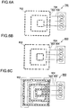
- each of nozzle arrangement parts 403, 503, 603 may have an annular structure of a substantially circular shape, or may be endless members having other shapes including an ellipse shape and a polygon shape other than a rectangle such as a triangle and a pentagon.
- the nozzle arrangement parts of the water conduit pipes of the intake-air cooling device are disposed in a concentric fashion in each of the first to third embodiments, the nozzle arrangement parts only need to be at least endless members and to have different perimeters.
- the arrangement is not limited to a concentric fashion. Specifically, it is sufficient if water conduit pipes having the same shape are arranged in an endless fashion with perimeters different from one another.
- nozzle arrangement parts 703, 803, 903 may be arranged not in a concentric fashion but in an arrangement in which the nozzle arrangement parts are eccentric to each other.
Landscapes
- Engineering & Computer Science (AREA)
- Chemical & Material Sciences (AREA)
- Combustion & Propulsion (AREA)
- Mechanical Engineering (AREA)
- General Engineering & Computer Science (AREA)
- Physics & Mathematics (AREA)
- Fluid Mechanics (AREA)
- Structures Of Non-Positive Displacement Pumps (AREA)
- Control Of Positive-Displacement Pumps (AREA)
- Compressor (AREA)
Claims (4)
- Dispositif (200 ; 500 ; 800) de refroidissement de l'air d'admission, monté d'un côté d'étage arrière d'un préfiltre (24) monté d'un côté d'entrée d'air d'admission d'un conduit (12) d'air d'admission, pour conduire de l'air d'admission d'une entrée (22) d'air d'admission à un compresseur (14), afin de refroidir l'air d'admission en pulvérisant de l'eau sur l'air d'admission, le dispositif (200 ; 500 ; 800) de refroidissement d'air d'admission comprenant :une pluralité de buses (202 ; 502 ; 802) configurées pour pulvériser l'eau sur l'air d'admission ;une pluralité de tuyaux (204 ; 504 ; 804) de conduite d'eau, chacun comprenant une partie (203 ; 503 ; 803) d'agencement de buses, sur laquelle la pluralité de buses (202 ; 502 ; 802) est montée dans une direction axiale des tuyaux (204 ; 504 ; 804) de conduite d'eau ; etune pluralité de pompes (P1, P2, P3) d'alimentation prévues pour les tuyaux (204 ; 504 ; 804) de conduite d'eau respectifs et configurées pour envoyer l'eau à l'un correspondant de la pluralité de tuyaux (204 ; 504 ; 804) de conduite d'eau,dans lequel chacune des parties (203 ; 503 ; 803) d'agencement de buses de la pluralité de tuyaux (204 ; 504 ; 804) de conduite d'eau est un élément sans fin ayant une structure annulaire d'un périmètre différent,dans lequel les parties (203 ; 503 ; 803) d'agencement de buses de la pluralité de tuyaux (204 ; 504 ; 804) de conduite d'eau sont disposées concentriquement ou excentriquement, etdans lequel la pluralité de buses (202 ; 502 ; 802) est disposée de manière à avoir une répartition, dans laquelle une densité augmente d'une partie des tuyaux (204 ; 504 ; 804) de conduite d'eau communiquant avec les pompes (P1, P2, P3) d'alimentation à une partie opposée à cette partie.
- Dispositif (300 ; 600 ; 900) de refroidissement d'air d'admission monté d'un côté d'étage arrière d'un préfiltre (24) monté d'un côté d'entrée d'air d'admission d'un conduit (12) d'air d'admission, pour conduire de l'air d'admission d'une entrée (22) d'air d'admission à un compresseur (14), afin de refroidir l'air d'admission en pulvérisant de l'eau sur l'air d'admission, le dispositif (300 ; 600 ; 900) de refroidissement d'air d'admission comprenant :une pluralité de buses (302 ; 602 ; 902) configurées pour pulvériser l'eau sur l'air d'admission ;une pluralité de tuyaux (304 ; 604 ; 904) de conduite d'eau, chacun comprenant une partie (303 ; 603 ; 903) d'agencement de buses, sur laquelle la pluralité de buses (302 ; 602 ; 902) est montée dans une direction axiale des tuyaux (304 ; 604 ; 804) de conduite d'eau ; etune pluralité de pompes (P1, P2, P3) d'alimentation prévues pour les tuyaux (304 ; 604 ; 904) de conduite d'eau respectifs et configurées pour envoyer l'eau à l'un correspondant de la pluralité de tuyaux (304 ; 504 ; 804) de conduite d'eau,dans lequel chacune des parties (303 ; 603 ; 903) d'agencement de buses de la pluralité de tuyaux (304 ; 604 ; 904) de conduite d'eau est un élément sans fin ayant une structure annulaire d'un périmètre différent,dans lequel les parties (303 ; 603 ; 903) d'agencement de buses de la pluralité de tuyaux (304 ; 604 ; 904) de conduite d'eau sont disposées concentriquement ou excentriquement, etdans lequel chacune des parties (303 ; 603 ; 903) d'agencement de buses de la pluralité de tuyaux (304 ; 604 ; 904) de conduite d'eau est subdivisée de manière intermittente et l'eau est envoyée à chaque partie subdivisée des parties (303 ; 603 ; 903) d'agencement de buses des tuyaux (304 ; 604 ; 904) de conduite d'eau, à partir des pompes (P1, P2, P3) d'alimentation.
- Dispositif (200 ; 300 ; 500 ; 600 ; 800 ; 900) de refroidissement d'air d'admission suivant la revendication 1 ou 2,
dans lequel les pompes (P1, P2, P3) d'alimentation sont des pompes à vitesse variable aptes à régler un débit de l'eau par une commande à inverseur. - Dispositif (200 ; 300 ; 500 ; 600 ; 800 ; 900) de refroidissement d'air d'admission suivant la revendication 3,
dans lequel les pompes (P1, P2, P3) d'alimentation sont configurées pour régler le débit de l'eau sur la base d'au moins l'un d'une température de l'air d'admission, d'une humidité de l'air d'admission, d'un degré d'ouverture des aubes (15) directrices d'entrée du compresseur (14) et d'une charge d'une turbine (18) à gaz.
Applications Claiming Priority (2)
| Application Number | Priority Date | Filing Date | Title |
|---|---|---|---|
| JP2013064453A JP6180145B2 (ja) | 2013-03-26 | 2013-03-26 | 吸気冷却装置 |
| PCT/JP2014/051864 WO2014156277A1 (fr) | 2013-03-26 | 2014-01-28 | Dispositif de refroidissement d'air d'admission |
Publications (3)
| Publication Number | Publication Date |
|---|---|
| EP2980384A1 EP2980384A1 (fr) | 2016-02-03 |
| EP2980384A4 EP2980384A4 (fr) | 2016-11-16 |
| EP2980384B1 true EP2980384B1 (fr) | 2020-02-19 |
Family
ID=51623279
Family Applications (1)
| Application Number | Title | Priority Date | Filing Date |
|---|---|---|---|
| EP14775523.5A Active EP2980384B1 (fr) | 2013-03-26 | 2014-01-28 | Dispositif de refroidissement d'air d'admission |
Country Status (5)
| Country | Link |
|---|---|
| US (1) | US9790858B2 (fr) |
| EP (1) | EP2980384B1 (fr) |
| JP (1) | JP6180145B2 (fr) |
| TW (1) | TWI557312B (fr) |
| WO (1) | WO2014156277A1 (fr) |
Families Citing this family (49)
| Publication number | Priority date | Publication date | Assignee | Title |
|---|---|---|---|---|
| US9650879B2 (en) | 2012-11-16 | 2017-05-16 | Us Well Services Llc | Torsional coupling for electric hydraulic fracturing fluid pumps |
| US10407990B2 (en) | 2012-11-16 | 2019-09-10 | U.S. Well Services, LLC | Slide out pump stand for hydraulic fracturing equipment |
| US9410410B2 (en) | 2012-11-16 | 2016-08-09 | Us Well Services Llc | System for pumping hydraulic fracturing fluid using electric pumps |
| US10020711B2 (en) | 2012-11-16 | 2018-07-10 | U.S. Well Services, LLC | System for fueling electric powered hydraulic fracturing equipment with multiple fuel sources |
| US9970278B2 (en) | 2012-11-16 | 2018-05-15 | U.S. Well Services, LLC | System for centralized monitoring and control of electric powered hydraulic fracturing fleet |
| US10232332B2 (en) * | 2012-11-16 | 2019-03-19 | U.S. Well Services, Inc. | Independent control of auger and hopper assembly in electric blender system |
| US10036238B2 (en) | 2012-11-16 | 2018-07-31 | U.S. Well Services, LLC | Cable management of electric powered hydraulic fracturing pump unit |
| US11959371B2 (en) | 2012-11-16 | 2024-04-16 | Us Well Services, Llc | Suction and discharge lines for a dual hydraulic fracturing unit |
| US9995218B2 (en) * | 2012-11-16 | 2018-06-12 | U.S. Well Services, LLC | Turbine chilling for oil field power generation |
| US9893500B2 (en) | 2012-11-16 | 2018-02-13 | U.S. Well Services, LLC | Switchgear load sharing for oil field equipment |
| US11449018B2 (en) | 2012-11-16 | 2022-09-20 | U.S. Well Services, LLC | System and method for parallel power and blackout protection for electric powered hydraulic fracturing |
| US9745840B2 (en) | 2012-11-16 | 2017-08-29 | Us Well Services Llc | Electric powered pump down |
| NO336863B1 (no) * | 2013-06-18 | 2015-11-16 | Vetco Gray Scandinavia As | Undersjøisk varmeveksler |
| JP6165514B2 (ja) * | 2013-06-19 | 2017-07-19 | 三菱日立パワーシステムズ株式会社 | 噴霧冷却装置 |
| EP2824285B1 (fr) * | 2013-07-11 | 2016-03-16 | Alstom Technology Ltd | Turbine à gaz comprenant un système de contrôle du flux d'entrée |
| CA2908276C (fr) | 2014-10-14 | 2022-11-01 | Us Well Services Llc | Alimentation parallele et protection contre une panne totale pour la fracturation hydraulique electrique |
| US9932856B2 (en) * | 2014-11-22 | 2018-04-03 | General Electric Company | Cooling apparatus for turbomachinery with method of installation |
| US10267234B2 (en) * | 2015-07-06 | 2019-04-23 | Dresser-Rand Company | Motive air conditioning system for gas turbines |
| US12078110B2 (en) | 2015-11-20 | 2024-09-03 | Us Well Services, Llc | System for gas compression on electric hydraulic fracturing fleets |
| KR101835421B1 (ko) * | 2015-12-31 | 2018-03-08 | 한국항공우주연구원 | 습식 압축용 환형 분사 장치 |
| US10371048B2 (en) * | 2016-02-22 | 2019-08-06 | Mitsubishi Hitachi Power Systems, Ltd. | Combustor and gas turbine |
| US12027831B2 (en) | 2016-04-15 | 2024-07-02 | U.S. Well Services, LLC | Switchgear load sharing for oil field equipment |
| US10378447B2 (en) * | 2016-09-30 | 2019-08-13 | General Electric Company | System and method for purging fuel or coolant from turbomachine |
| US11181107B2 (en) | 2016-12-02 | 2021-11-23 | U.S. Well Services, LLC | Constant voltage power distribution system for use with an electric hydraulic fracturing system |
| US11022038B2 (en) | 2017-05-04 | 2021-06-01 | General Electric Company | Compressor circumferential fluid distribution system |
| US10280724B2 (en) | 2017-07-07 | 2019-05-07 | U.S. Well Services, Inc. | Hydraulic fracturing equipment with non-hydraulic power |
| US11067481B2 (en) | 2017-10-05 | 2021-07-20 | U.S. Well Services, LLC | Instrumented fracturing slurry flow system and method |
| WO2019084283A1 (fr) | 2017-10-25 | 2019-05-02 | U.S. Well Services, LLC | Système et procédé de fracturation intelligente |
| US10648311B2 (en) | 2017-12-05 | 2020-05-12 | U.S. Well Services, LLC | High horsepower pumping configuration for an electric hydraulic fracturing system |
| US11114857B2 (en) | 2018-02-05 | 2021-09-07 | U.S. Well Services, LLC | Microgrid electrical load management |
| US11035207B2 (en) | 2018-04-16 | 2021-06-15 | U.S. Well Services, LLC | Hybrid hydraulic fracturing fleet |
| WO2020056258A1 (fr) | 2018-09-14 | 2020-03-19 | U.S. Well Services, LLC | Support de colonne montante pour sites de puits |
| WO2020081313A1 (fr) | 2018-10-09 | 2020-04-23 | U.S. Well Services, LLC | Système de pompe de fracturation hydraulique électrique comprenant des remorques de fracturation pour pompe à pistons multiples à alimentation électrique unique, unités de filtration, et plate-forme coulissante |
| US11578577B2 (en) | 2019-03-20 | 2023-02-14 | U.S. Well Services, LLC | Oversized switchgear trailer for electric hydraulic fracturing |
| US11728709B2 (en) | 2019-05-13 | 2023-08-15 | U.S. Well Services, LLC | Encoderless vector control for VFD in hydraulic fracturing applications |
| AR119134A1 (es) | 2019-06-10 | 2021-11-24 | U S Well Services Llc | Calentador integrado de gas de combustión para equipos móviles de acondicionamiento de combustible |
| WO2021022048A1 (fr) | 2019-08-01 | 2021-02-04 | U.S. Well Services, LLC | Système de stockage d'énergie à haute capacité pour fracturation hydraulique électrique |
| US11459863B2 (en) | 2019-10-03 | 2022-10-04 | U.S. Well Services, LLC | Electric powered hydraulic fracturing pump system with single electric powered multi-plunger fracturing pump |
| US12012952B2 (en) | 2019-11-18 | 2024-06-18 | U.S. Well Services, LLC | Electrically actuated valves for manifold trailers or skids |
| US12509974B2 (en) | 2019-12-27 | 2025-12-30 | U.S. Well Services, LLC | Systems and methods for fluid end health monitoring |
| US11009162B1 (en) | 2019-12-27 | 2021-05-18 | U.S. Well Services, LLC | System and method for integrated flow supply line |
| US11885206B2 (en) | 2019-12-30 | 2024-01-30 | U.S. Well Services, LLC | Electric motor driven transportation mechanisms for fracturing blenders |
| US11846167B2 (en) | 2019-12-30 | 2023-12-19 | U.S. Well Services, LLC | Blender tub overflow catch |
| US11492886B2 (en) | 2019-12-31 | 2022-11-08 | U.S. Wells Services, LLC | Self-regulating FRAC pump suction stabilizer/dampener |
| US11960305B2 (en) | 2019-12-31 | 2024-04-16 | U.S. Well Services, LLC | Automated blender bucket testing and calibration |
| US11560887B2 (en) | 2019-12-31 | 2023-01-24 | U.S. Well Services, LLC | Segmented fluid end plunger pump |
| CN112173137B (zh) * | 2020-09-25 | 2022-09-30 | 中国直升机设计研究所 | 一种直升机降温进气道 |
| CN113638892B (zh) * | 2021-08-10 | 2022-06-21 | 萨震压缩机(上海)有限公司 | 一种可进行进气口增压的高速离心式空压机 |
| US20250122833A1 (en) * | 2023-10-17 | 2025-04-17 | Ge Infrastructure Technology Llc | Airless sprint & water wash system |
Family Cites Families (17)
| Publication number | Priority date | Publication date | Assignee | Title |
|---|---|---|---|---|
| JPH0777060A (ja) | 1993-09-03 | 1995-03-20 | Nippon Steel Corp | 高炉ガス回収装置及び高炉炉頂圧回収タービンのバイパス運転方法 |
| JPH08284685A (ja) | 1995-04-10 | 1996-10-29 | Mitsubishi Heavy Ind Ltd | ガスタービンの吸気冷却装置 |
| JPH1113486A (ja) * | 1997-06-27 | 1999-01-19 | Hitachi Ltd | ガスタービン |
| JP3538807B2 (ja) | 1999-04-05 | 2004-06-14 | 吉秀 中村 | ガスタービンプラント |
| GB2365074B (en) * | 1999-07-13 | 2003-08-13 | Allison Advanced Dev Co | Gas turbine engine power boost using micro droplet liquid injection |
| JP3691711B2 (ja) * | 2000-02-21 | 2005-09-07 | 株式会社日立製作所 | ガスタービンプラント |
| US6478289B1 (en) * | 2000-11-06 | 2002-11-12 | General Electric Company | Apparatus and methods for controlling the supply of water mist to a gas-turbine compressor |
| GB2382848A (en) * | 2001-12-06 | 2003-06-11 | Alstom | Gas turbine wet compression |
| DE10256193A1 (de) * | 2002-12-02 | 2004-06-09 | Alstom Technology Ltd | Verfahren zur Steuerung der Flüssigkeitseinspritzung in einen Zuströmkanal einer Kraft- oder Arbeitsmaschine |
| US7416137B2 (en) | 2003-01-22 | 2008-08-26 | Vast Power Systems, Inc. | Thermodynamic cycles using thermal diluent |
| ITMI20031245A1 (it) * | 2003-06-19 | 2004-12-20 | Edoardo Lossa S P A | Sistema di trattamento e messa in pressione d'acqua per il raffreddamento adiabatico d'aria comburente |
| CN1788143B (zh) * | 2004-06-14 | 2011-07-06 | 燃气涡轮效率股份有限公司 | 用于收集和处理来自发动机清洁的废水的系统和装置 |
| GB2429937A (en) * | 2005-09-08 | 2007-03-14 | Siemens Ind Turbomachinery Ltd | Apparatus for mixing gas streams |
| TW200930850A (en) | 2008-01-03 | 2009-07-16 | Green Energy Technology Inc | Cooling structure for body of crystal growth furnace |
| JP5523881B2 (ja) * | 2009-08-31 | 2014-06-18 | 株式会社東芝 | ガスタービン吸気冷却装置 |
| JP2011111944A (ja) * | 2009-11-25 | 2011-06-09 | Toshiba Corp | ガスタービン吸気冷却装置 |
| US8978386B2 (en) * | 2010-09-30 | 2015-03-17 | Mitsubishi Hitachi Power Systems, Ltd. | Gas turbine system, control device for gas turbine system, and control method for gas turbine system |
-
2013
- 2013-03-26 JP JP2013064453A patent/JP6180145B2/ja active Active
-
2014
- 2014-01-27 TW TW103102940A patent/TWI557312B/zh active
- 2014-01-28 US US14/769,237 patent/US9790858B2/en active Active
- 2014-01-28 WO PCT/JP2014/051864 patent/WO2014156277A1/fr not_active Ceased
- 2014-01-28 EP EP14775523.5A patent/EP2980384B1/fr active Active
Non-Patent Citations (1)
| Title |
|---|
| None * |
Also Published As
| Publication number | Publication date |
|---|---|
| TW201502358A (zh) | 2015-01-16 |
| JP2014190182A (ja) | 2014-10-06 |
| US9790858B2 (en) | 2017-10-17 |
| US20150377133A1 (en) | 2015-12-31 |
| WO2014156277A1 (fr) | 2014-10-02 |
| TWI557312B (zh) | 2016-11-11 |
| JP6180145B2 (ja) | 2017-08-16 |
| EP2980384A4 (fr) | 2016-11-16 |
| EP2980384A1 (fr) | 2016-02-03 |
Similar Documents
| Publication | Publication Date | Title |
|---|---|---|
| EP2980384B1 (fr) | Dispositif de refroidissement d'air d'admission | |
| US8465573B2 (en) | System and method for conditioning air flow to a gas turbine | |
| RU2318122C2 (ru) | Диффузор наземного или авиационного газотурбинного двигателя | |
| US8257025B2 (en) | Combustion turbine including a diffuser section with cooling fluid passageways and associated methods | |
| RU2365821C2 (ru) | Диффузор для кольцевой камеры сгорания, в частности для турбинного двигателя самолета, а также камера сгорания и авиационный турбовинтовой двигатель, содержащие такой диффузор | |
| US20120186261A1 (en) | System and method for a gas turbine exhaust diffuser | |
| US7717667B2 (en) | Method and apparatus for operating gas turbine engines | |
| CN1217091C (zh) | 闭路冷却叶片涡轮机 | |
| US9488191B2 (en) | Gas turbine diffuser strut including coanda flow injection | |
| KR20190008346A (ko) | 산업용 가스터빈엔진을 새로 장착하기 위한 프로세스 및 새로 장착된 산업용 가스터빈엔진을 포함하는 파워플랜트 | |
| JP2008255987A (ja) | ターボ機械の冷却及びシーリング空気システムのためのミキサ | |
| US20130199202A1 (en) | System and method for gas turbine inlet air heating | |
| US20090038313A1 (en) | Method and apparatus for supplying pressure for spray inlet temperature suppressor of gas turbines | |
| CA2606580C (fr) | Plenum d'ouie d'entree ameliore pour turbine a gaz | |
| US20130091845A1 (en) | Power plant and method for retrofit | |
| RU2519678C1 (ru) | Охлаждаемая турбина газотурбинного двигателя | |
| CN102128085A (zh) | 用于燃气涡轮机功率增大的系统和方法 | |
| JP2020515798A (ja) | ガスタービンエンジンの燃焼器セクションにおける冷却流体の二重利用のための導管配置を備えたシステム | |
| US10794215B2 (en) | Cooling arrangement for a turbine casing of a gas turbine engine | |
| RU2347091C1 (ru) | Газотурбинный двигатель | |
| RU2261350C2 (ru) | Турбина газотурбинного двигателя | |
| US20130312385A1 (en) | Gas turbine system having a plasma actuator flow control arrangement | |
| RU2180046C2 (ru) | Уплотнительное устройство за компрессором газотурбинного двигателя | |
| RU2525379C1 (ru) | Способ охлаждения рабочих лопаток турбины двухконтурного газотурбинного двигателя и устройство для его осуществления | |
| RU2347914C1 (ru) | Многоступенчатая турбина газотурбинного двигателя |
Legal Events
| Date | Code | Title | Description |
|---|---|---|---|
| PUAI | Public reference made under article 153(3) epc to a published international application that has entered the european phase |
Free format text: ORIGINAL CODE: 0009012 |
|
| 17P | Request for examination filed |
Effective date: 20150730 |
|
| AK | Designated contracting states |
Kind code of ref document: A1 Designated state(s): AL AT BE BG CH CY CZ DE DK EE ES FI FR GB GR HR HU IE IS IT LI LT LU LV MC MK MT NL NO PL PT RO RS SE SI SK SM TR |
|
| AX | Request for extension of the european patent |
Extension state: BA ME |
|
| DAX | Request for extension of the european patent (deleted) | ||
| A4 | Supplementary search report drawn up and despatched |
Effective date: 20161013 |
|
| RIC1 | Information provided on ipc code assigned before grant |
Ipc: F04B 49/06 20060101ALI20161007BHEP Ipc: F02C 7/04 20060101ALI20161007BHEP Ipc: F04B 17/03 20060101ALI20161007BHEP Ipc: F02C 7/143 20060101ALI20161007BHEP Ipc: F02C 3/30 20060101AFI20161007BHEP |
|
| STAA | Information on the status of an ep patent application or granted ep patent |
Free format text: STATUS: EXAMINATION IS IN PROGRESS |
|
| 17Q | First examination report despatched |
Effective date: 20171123 |
|
| GRAP | Despatch of communication of intention to grant a patent |
Free format text: ORIGINAL CODE: EPIDOSNIGR1 |
|
| STAA | Information on the status of an ep patent application or granted ep patent |
Free format text: STATUS: GRANT OF PATENT IS INTENDED |
|
| INTG | Intention to grant announced |
Effective date: 20191009 |
|
| GRAS | Grant fee paid |
Free format text: ORIGINAL CODE: EPIDOSNIGR3 |
|
| GRAA | (expected) grant |
Free format text: ORIGINAL CODE: 0009210 |
|
| STAA | Information on the status of an ep patent application or granted ep patent |
Free format text: STATUS: THE PATENT HAS BEEN GRANTED |
|
| AK | Designated contracting states |
Kind code of ref document: B1 Designated state(s): AL AT BE BG CH CY CZ DE DK EE ES FI FR GB GR HR HU IE IS IT LI LT LU LV MC MK MT NL NO PL PT RO RS SE SI SK SM TR |
|
| REG | Reference to a national code |
Ref country code: CH Ref legal event code: EP |
|
| REG | Reference to a national code |
Ref country code: DE Ref legal event code: R096 Ref document number: 602014061239 Country of ref document: DE |
|
| REG | Reference to a national code |
Ref country code: AT Ref legal event code: REF Ref document number: 1235229 Country of ref document: AT Kind code of ref document: T Effective date: 20200315 |
|
| REG | Reference to a national code |
Ref country code: IE Ref legal event code: FG4D |
|
| REG | Reference to a national code |
Ref country code: NL Ref legal event code: MP Effective date: 20200219 |
|
| PG25 | Lapsed in a contracting state [announced via postgrant information from national office to epo] |
Ref country code: FI Free format text: LAPSE BECAUSE OF FAILURE TO SUBMIT A TRANSLATION OF THE DESCRIPTION OR TO PAY THE FEE WITHIN THE PRESCRIBED TIME-LIMIT Effective date: 20200219 Ref country code: NO Free format text: LAPSE BECAUSE OF FAILURE TO SUBMIT A TRANSLATION OF THE DESCRIPTION OR TO PAY THE FEE WITHIN THE PRESCRIBED TIME-LIMIT Effective date: 20200519 Ref country code: RS Free format text: LAPSE BECAUSE OF FAILURE TO SUBMIT A TRANSLATION OF THE DESCRIPTION OR TO PAY THE FEE WITHIN THE PRESCRIBED TIME-LIMIT Effective date: 20200219 |
|
| REG | Reference to a national code |
Ref country code: LT Ref legal event code: MG4D |
|
| PG25 | Lapsed in a contracting state [announced via postgrant information from national office to epo] |
Ref country code: GR Free format text: LAPSE BECAUSE OF FAILURE TO SUBMIT A TRANSLATION OF THE DESCRIPTION OR TO PAY THE FEE WITHIN THE PRESCRIBED TIME-LIMIT Effective date: 20200520 Ref country code: IS Free format text: LAPSE BECAUSE OF FAILURE TO SUBMIT A TRANSLATION OF THE DESCRIPTION OR TO PAY THE FEE WITHIN THE PRESCRIBED TIME-LIMIT Effective date: 20200619 Ref country code: BG Free format text: LAPSE BECAUSE OF FAILURE TO SUBMIT A TRANSLATION OF THE DESCRIPTION OR TO PAY THE FEE WITHIN THE PRESCRIBED TIME-LIMIT Effective date: 20200519 Ref country code: HR Free format text: LAPSE BECAUSE OF FAILURE TO SUBMIT A TRANSLATION OF THE DESCRIPTION OR TO PAY THE FEE WITHIN THE PRESCRIBED TIME-LIMIT Effective date: 20200219 Ref country code: SE Free format text: LAPSE BECAUSE OF FAILURE TO SUBMIT A TRANSLATION OF THE DESCRIPTION OR TO PAY THE FEE WITHIN THE PRESCRIBED TIME-LIMIT Effective date: 20200219 Ref country code: LV Free format text: LAPSE BECAUSE OF FAILURE TO SUBMIT A TRANSLATION OF THE DESCRIPTION OR TO PAY THE FEE WITHIN THE PRESCRIBED TIME-LIMIT Effective date: 20200219 |
|
| PG25 | Lapsed in a contracting state [announced via postgrant information from national office to epo] |
Ref country code: NL Free format text: LAPSE BECAUSE OF FAILURE TO SUBMIT A TRANSLATION OF THE DESCRIPTION OR TO PAY THE FEE WITHIN THE PRESCRIBED TIME-LIMIT Effective date: 20200219 |
|
| PG25 | Lapsed in a contracting state [announced via postgrant information from national office to epo] |
Ref country code: DK Free format text: LAPSE BECAUSE OF FAILURE TO SUBMIT A TRANSLATION OF THE DESCRIPTION OR TO PAY THE FEE WITHIN THE PRESCRIBED TIME-LIMIT Effective date: 20200219 Ref country code: ES Free format text: LAPSE BECAUSE OF FAILURE TO SUBMIT A TRANSLATION OF THE DESCRIPTION OR TO PAY THE FEE WITHIN THE PRESCRIBED TIME-LIMIT Effective date: 20200219 Ref country code: CZ Free format text: LAPSE BECAUSE OF FAILURE TO SUBMIT A TRANSLATION OF THE DESCRIPTION OR TO PAY THE FEE WITHIN THE PRESCRIBED TIME-LIMIT Effective date: 20200219 Ref country code: LT Free format text: LAPSE BECAUSE OF FAILURE TO SUBMIT A TRANSLATION OF THE DESCRIPTION OR TO PAY THE FEE WITHIN THE PRESCRIBED TIME-LIMIT Effective date: 20200219 Ref country code: RO Free format text: LAPSE BECAUSE OF FAILURE TO SUBMIT A TRANSLATION OF THE DESCRIPTION OR TO PAY THE FEE WITHIN THE PRESCRIBED TIME-LIMIT Effective date: 20200219 Ref country code: EE Free format text: LAPSE BECAUSE OF FAILURE TO SUBMIT A TRANSLATION OF THE DESCRIPTION OR TO PAY THE FEE WITHIN THE PRESCRIBED TIME-LIMIT Effective date: 20200219 Ref country code: SM Free format text: LAPSE BECAUSE OF FAILURE TO SUBMIT A TRANSLATION OF THE DESCRIPTION OR TO PAY THE FEE WITHIN THE PRESCRIBED TIME-LIMIT Effective date: 20200219 Ref country code: SK Free format text: LAPSE BECAUSE OF FAILURE TO SUBMIT A TRANSLATION OF THE DESCRIPTION OR TO PAY THE FEE WITHIN THE PRESCRIBED TIME-LIMIT Effective date: 20200219 Ref country code: PT Free format text: LAPSE BECAUSE OF FAILURE TO SUBMIT A TRANSLATION OF THE DESCRIPTION OR TO PAY THE FEE WITHIN THE PRESCRIBED TIME-LIMIT Effective date: 20200712 |
|
| REG | Reference to a national code |
Ref country code: AT Ref legal event code: MK05 Ref document number: 1235229 Country of ref document: AT Kind code of ref document: T Effective date: 20200219 |
|
| REG | Reference to a national code |
Ref country code: DE Ref legal event code: R097 Ref document number: 602014061239 Country of ref document: DE |
|
| REG | Reference to a national code |
Ref country code: DE Ref legal event code: R082 Ref document number: 602014061239 Country of ref document: DE Representative=s name: HENKEL & PARTNER MBB PATENTANWALTSKANZLEI, REC, DE Ref country code: DE Ref legal event code: R081 Ref document number: 602014061239 Country of ref document: DE Owner name: MITSUBISHI POWER, LTD., JP Free format text: FORMER OWNER: MITSUBISHI HITACHI POWER SYSTEMS, LTD., YOKOHAMA-SHI, KANAGAWA, JP |
|
| PLBE | No opposition filed within time limit |
Free format text: ORIGINAL CODE: 0009261 |
|
| STAA | Information on the status of an ep patent application or granted ep patent |
Free format text: STATUS: NO OPPOSITION FILED WITHIN TIME LIMIT |
|
| 26N | No opposition filed |
Effective date: 20201120 |
|
| PG25 | Lapsed in a contracting state [announced via postgrant information from national office to epo] |
Ref country code: IT Free format text: LAPSE BECAUSE OF FAILURE TO SUBMIT A TRANSLATION OF THE DESCRIPTION OR TO PAY THE FEE WITHIN THE PRESCRIBED TIME-LIMIT Effective date: 20200219 Ref country code: AT Free format text: LAPSE BECAUSE OF FAILURE TO SUBMIT A TRANSLATION OF THE DESCRIPTION OR TO PAY THE FEE WITHIN THE PRESCRIBED TIME-LIMIT Effective date: 20200219 |
|
| PG25 | Lapsed in a contracting state [announced via postgrant information from national office to epo] |
Ref country code: PL Free format text: LAPSE BECAUSE OF FAILURE TO SUBMIT A TRANSLATION OF THE DESCRIPTION OR TO PAY THE FEE WITHIN THE PRESCRIBED TIME-LIMIT Effective date: 20200219 Ref country code: SI Free format text: LAPSE BECAUSE OF FAILURE TO SUBMIT A TRANSLATION OF THE DESCRIPTION OR TO PAY THE FEE WITHIN THE PRESCRIBED TIME-LIMIT Effective date: 20200219 |
|
| PG25 | Lapsed in a contracting state [announced via postgrant information from national office to epo] |
Ref country code: MC Free format text: LAPSE BECAUSE OF FAILURE TO SUBMIT A TRANSLATION OF THE DESCRIPTION OR TO PAY THE FEE WITHIN THE PRESCRIBED TIME-LIMIT Effective date: 20200219 |
|
| REG | Reference to a national code |
Ref country code: CH Ref legal event code: PL |
|
| GBPC | Gb: european patent ceased through non-payment of renewal fee |
Effective date: 20210128 |
|
| PG25 | Lapsed in a contracting state [announced via postgrant information from national office to epo] |
Ref country code: LU Free format text: LAPSE BECAUSE OF NON-PAYMENT OF DUE FEES Effective date: 20210128 |
|
| REG | Reference to a national code |
Ref country code: BE Ref legal event code: MM Effective date: 20210131 |
|
| PG25 | Lapsed in a contracting state [announced via postgrant information from national office to epo] |
Ref country code: FR Free format text: LAPSE BECAUSE OF NON-PAYMENT OF DUE FEES Effective date: 20210131 |
|
| PG25 | Lapsed in a contracting state [announced via postgrant information from national office to epo] |
Ref country code: LI Free format text: LAPSE BECAUSE OF NON-PAYMENT OF DUE FEES Effective date: 20210131 Ref country code: CH Free format text: LAPSE BECAUSE OF NON-PAYMENT OF DUE FEES Effective date: 20210131 Ref country code: GB Free format text: LAPSE BECAUSE OF NON-PAYMENT OF DUE FEES Effective date: 20210128 |
|
| PG25 | Lapsed in a contracting state [announced via postgrant information from national office to epo] |
Ref country code: IE Free format text: LAPSE BECAUSE OF NON-PAYMENT OF DUE FEES Effective date: 20210128 |
|
| PG25 | Lapsed in a contracting state [announced via postgrant information from national office to epo] |
Ref country code: BE Free format text: LAPSE BECAUSE OF NON-PAYMENT OF DUE FEES Effective date: 20210131 |
|
| PG25 | Lapsed in a contracting state [announced via postgrant information from national office to epo] |
Ref country code: HU Free format text: LAPSE BECAUSE OF FAILURE TO SUBMIT A TRANSLATION OF THE DESCRIPTION OR TO PAY THE FEE WITHIN THE PRESCRIBED TIME-LIMIT; INVALID AB INITIO Effective date: 20140128 |
|
| PG25 | Lapsed in a contracting state [announced via postgrant information from national office to epo] |
Ref country code: CY Free format text: LAPSE BECAUSE OF FAILURE TO SUBMIT A TRANSLATION OF THE DESCRIPTION OR TO PAY THE FEE WITHIN THE PRESCRIBED TIME-LIMIT Effective date: 20200219 |
|
| PG25 | Lapsed in a contracting state [announced via postgrant information from national office to epo] |
Ref country code: MK Free format text: LAPSE BECAUSE OF FAILURE TO SUBMIT A TRANSLATION OF THE DESCRIPTION OR TO PAY THE FEE WITHIN THE PRESCRIBED TIME-LIMIT Effective date: 20200219 |
|
| PG25 | Lapsed in a contracting state [announced via postgrant information from national office to epo] |
Ref country code: TR Free format text: LAPSE BECAUSE OF FAILURE TO SUBMIT A TRANSLATION OF THE DESCRIPTION OR TO PAY THE FEE WITHIN THE PRESCRIBED TIME-LIMIT Effective date: 20200219 |
|
| PG25 | Lapsed in a contracting state [announced via postgrant information from national office to epo] |
Ref country code: MT Free format text: LAPSE BECAUSE OF FAILURE TO SUBMIT A TRANSLATION OF THE DESCRIPTION OR TO PAY THE FEE WITHIN THE PRESCRIBED TIME-LIMIT Effective date: 20200219 |
|
| PGFP | Annual fee paid to national office [announced via postgrant information from national office to epo] |
Ref country code: DE Payment date: 20251203 Year of fee payment: 13 |