EP2980443A1 - Zusammengesetztes dämpfungsmaterial - Google Patents
Zusammengesetztes dämpfungsmaterial Download PDFInfo
- Publication number
- EP2980443A1 EP2980443A1 EP13880324.2A EP13880324A EP2980443A1 EP 2980443 A1 EP2980443 A1 EP 2980443A1 EP 13880324 A EP13880324 A EP 13880324A EP 2980443 A1 EP2980443 A1 EP 2980443A1
- Authority
- EP
- European Patent Office
- Prior art keywords
- needle
- dielectric
- damping
- piezoelectric fiber
- present
- Prior art date
- Legal status (The legal status is an assumption and is not a legal conclusion. Google has not performed a legal analysis and makes no representation as to the accuracy of the status listed.)
- Withdrawn
Links
Images


Classifications
-
- F—MECHANICAL ENGINEERING; LIGHTING; HEATING; WEAPONS; BLASTING
- F16—ENGINEERING ELEMENTS AND UNITS; GENERAL MEASURES FOR PRODUCING AND MAINTAINING EFFECTIVE FUNCTIONING OF MACHINES OR INSTALLATIONS; THERMAL INSULATION IN GENERAL
- F16F—SPRINGS; SHOCK-ABSORBERS; MEANS FOR DAMPING VIBRATION
- F16F13/00—Units comprising springs of the non-fluid type as well as vibration-dampers, shock-absorbers, or fluid springs
- F16F13/04—Units comprising springs of the non-fluid type as well as vibration-dampers, shock-absorbers, or fluid springs comprising both a plastics spring and a damper, e.g. a friction damper
-
- G—PHYSICS
- G10—MUSICAL INSTRUMENTS; ACOUSTICS
- G10K—SOUND-PRODUCING DEVICES; METHODS OR DEVICES FOR PROTECTING AGAINST, OR FOR DAMPING, NOISE OR OTHER ACOUSTIC WAVES IN GENERAL; ACOUSTICS NOT OTHERWISE PROVIDED FOR
- G10K11/00—Methods or devices for transmitting, conducting or directing sound in general; Methods or devices for protecting against, or for damping, noise or other acoustic waves in general
- G10K11/16—Methods or devices for protecting against, or for damping, noise or other acoustic waves in general
- G10K11/162—Selection of materials
- G10K11/165—Particles in a matrix
-
- C—CHEMISTRY; METALLURGY
- C08—ORGANIC MACROMOLECULAR COMPOUNDS; THEIR PREPARATION OR CHEMICAL WORKING-UP; COMPOSITIONS BASED THEREON
- C08L—COMPOSITIONS OF MACROMOLECULAR COMPOUNDS
- C08L9/00—Compositions of homopolymers or copolymers of conjugated diene hydrocarbons
- C08L9/02—Copolymers with acrylonitrile
-
- F—MECHANICAL ENGINEERING; LIGHTING; HEATING; WEAPONS; BLASTING
- F16—ENGINEERING ELEMENTS AND UNITS; GENERAL MEASURES FOR PRODUCING AND MAINTAINING EFFECTIVE FUNCTIONING OF MACHINES OR INSTALLATIONS; THERMAL INSULATION IN GENERAL
- F16F—SPRINGS; SHOCK-ABSORBERS; MEANS FOR DAMPING VIBRATION
- F16F1/00—Springs
- F16F1/36—Springs made of rubber or other material having high internal friction, e.g. thermoplastic elastomers
- F16F1/3605—Springs made of rubber or other material having high internal friction, e.g. thermoplastic elastomers characterised by their material
-
- F—MECHANICAL ENGINEERING; LIGHTING; HEATING; WEAPONS; BLASTING
- F16—ENGINEERING ELEMENTS AND UNITS; GENERAL MEASURES FOR PRODUCING AND MAINTAINING EFFECTIVE FUNCTIONING OF MACHINES OR INSTALLATIONS; THERMAL INSULATION IN GENERAL
- F16F—SPRINGS; SHOCK-ABSORBERS; MEANS FOR DAMPING VIBRATION
- F16F15/00—Suppression of vibrations in systems; Means or arrangements for avoiding or reducing out-of-balance forces, e.g. due to motion
- F16F15/005—Suppression of vibrations in systems; Means or arrangements for avoiding or reducing out-of-balance forces, e.g. due to motion using electro- or magnetostrictive actuation means
-
- F—MECHANICAL ENGINEERING; LIGHTING; HEATING; WEAPONS; BLASTING
- F16—ENGINEERING ELEMENTS AND UNITS; GENERAL MEASURES FOR PRODUCING AND MAINTAINING EFFECTIVE FUNCTIONING OF MACHINES OR INSTALLATIONS; THERMAL INSULATION IN GENERAL
- F16F—SPRINGS; SHOCK-ABSORBERS; MEANS FOR DAMPING VIBRATION
- F16F15/00—Suppression of vibrations in systems; Means or arrangements for avoiding or reducing out-of-balance forces, e.g. due to motion
- F16F15/02—Suppression of vibrations of non-rotating, e.g. reciprocating systems; Suppression of vibrations of rotating systems by use of members not moving with the rotating systems
-
- C—CHEMISTRY; METALLURGY
- C08—ORGANIC MACROMOLECULAR COMPOUNDS; THEIR PREPARATION OR CHEMICAL WORKING-UP; COMPOSITIONS BASED THEREON
- C08K—Use of inorganic or non-macromolecular organic substances as compounding ingredients
- C08K3/00—Use of inorganic substances as compounding ingredients
- C08K3/18—Oxygen-containing compounds, e.g. metal carbonyls
- C08K3/20—Oxides; Hydroxides
- C08K3/22—Oxides; Hydroxides of metals
- C08K2003/2237—Oxides; Hydroxides of metals of titanium
- C08K2003/2241—Titanium dioxide
-
- C—CHEMISTRY; METALLURGY
- C08—ORGANIC MACROMOLECULAR COMPOUNDS; THEIR PREPARATION OR CHEMICAL WORKING-UP; COMPOSITIONS BASED THEREON
- C08K—Use of inorganic or non-macromolecular organic substances as compounding ingredients
- C08K2201/00—Specific properties of additives
- C08K2201/001—Conductive additives
-
- C—CHEMISTRY; METALLURGY
- C08—ORGANIC MACROMOLECULAR COMPOUNDS; THEIR PREPARATION OR CHEMICAL WORKING-UP; COMPOSITIONS BASED THEREON
- C08K—Use of inorganic or non-macromolecular organic substances as compounding ingredients
- C08K3/00—Use of inorganic substances as compounding ingredients
- C08K3/02—Elements
- C08K3/04—Carbon
-
- C—CHEMISTRY; METALLURGY
- C08—ORGANIC MACROMOLECULAR COMPOUNDS; THEIR PREPARATION OR CHEMICAL WORKING-UP; COMPOSITIONS BASED THEREON
- C08K—Use of inorganic or non-macromolecular organic substances as compounding ingredients
- C08K3/00—Use of inorganic substances as compounding ingredients
- C08K3/34—Silicon-containing compounds
-
- F—MECHANICAL ENGINEERING; LIGHTING; HEATING; WEAPONS; BLASTING
- F16—ENGINEERING ELEMENTS AND UNITS; GENERAL MEASURES FOR PRODUCING AND MAINTAINING EFFECTIVE FUNCTIONING OF MACHINES OR INSTALLATIONS; THERMAL INSULATION IN GENERAL
- F16F—SPRINGS; SHOCK-ABSORBERS; MEANS FOR DAMPING VIBRATION
- F16F2224/00—Materials; Material properties
- F16F2224/02—Materials; Material properties solids
- F16F2224/0283—Materials; Material properties solids piezoelectric; electro- or magnetostrictive
Definitions
- the present invention relates to a damping material for converting vibration energy into electrical energy to attenuate vibration, and in particular, relates to a composite damping material utilized for equipment anti-vibration, noise absorption, and the like.
- vibration and noise generated by various kinds of equipment have come to be viewed as a problem from the viewpoint of health management or environmental preservation.
- vibration, in particular, low frequency vibration increased by the spread of various kinds of precision machines such as an audio instrument or a personal computer
- the above points (1) and (2) relate to a stiff structure design for causing vibration not to occur
- the above point (3) relates to a flexible structure and employs an idea that it is preferable to allow vibration to occur freely and to attenuate the vibration quickly afterward.
- vibration attenuation there is proposed and implemented a method of reducing the amplitude rapidly to stop the vibration by converting the vibration energy of a vibrated body into heat to consume the energy.
- damping materials each utilizing the attenuation ability of the material itself.
- an organic polymer-based damping material in which a low molecular weight compound having a piezoelectric property, a dielectric property, and a conductive property is diffused into a non-piezoelectric organic polymer matrix, for example.
- the effect of such a damping material has a principle different from the principle of the conventional damping effect and attenuates the vibration by converting the vibration energy first into electric energy and then into thermal energy for consumption, and, since electric energy loss caused by a piezoelectricity-conductivity effect is added, the effect enables a more effective vibration attenuation (refer to Patent Literature 1 and Patent Literature 2, for example).
- the present invention has been achieved in consideration of the problems of the conventional techniques discussed above, and an object thereof is to provide a composite damping material capable of exhibiting a more effective damping effect in a low frequency range.
- the present invention achieved based on such finding is a composite damping material comprising a needle-like dielectric having a high dielectric constant, a piezoelectric fiber made of an organic material, and a polymer material serving as a matrix, wherein the needle-like dielectric and the piezoelectric fiber are mixed in the polymer material.
- the present invention is a composite damping material comprising a needle-like dielectric having a high dielectric constant, a piezoelectric fiber made of an organic material, a flat filler made of an inorganic material, conductive fine particles, and a polymer material serving as matrix, wherein the needle-like dielectric, the piezoelectric fiber, the flat filler, and the conductive fine particles are mixed in the polymer material.
- the present invention is also effective in a case that the needle-like dielectric is made of titanium dioxide.
- the present invention is also effective in a case that the needle-like dielectric comprises a needle-like core made of titanium dioxide, and a conductive material layer provided on a surface of the needle-like core.
- the present invention is also effective in a case that the piezoelectric fiber is made of a cellulose fiber.
- FIG. 1 is a cross-sectional schematic diagram to show an outline configuration of a composite damping material of the present invention.
- FIG. 2 (a) is a schematic diagram to show a size relationship of a needle-like dielectric used in the present invention.
- FIG. 2 (b) is a cross-sectional diagram to show a configuration of a needle-like dielectric in which a conductive material layer is provided on the surface of a titanium dioxide, and
- FIG. 2 (c) is a schematic diagram to show a size relationship of a piezoelectric fiber used in the present invention.
- a composite damping material 1 of the present invention includes a needle-like dielectric having a high dielectric constant 3 and a piezoelectric fiber 4 made of an organic material mixed into a polymer material 2 serving as a matrix, and preferably further includes a flat filler 5 made of an inorganic material and conductive fine particles 6 mixed into the polymer material 2.
- the polymer material 2 serving as a matrix is not limited in particular, and it is possible to use various elastomers or polymer resins.
- Examples of the elastomer used in the present invention include, for example, acryl rubber (ACR), butyl rubber (IIR), acrylonitrile-butadiene rubber (NBR), acrylonitrile-butadiene rubber blended with vinyl chloride resin (NBR/PVC), styrene-butadiene rubber (SBR), butadiene rubber (BR), natural rubber (NR), isoprene rubber (IR), butyl rubber (IIR), ethylene propylene rubber (EPM), chloroprene rubber (CR), and the like.
- ACR acryl rubber
- IIR acrylonitrile-butadiene rubber
- NBR/PVC acrylonitrile-butadiene rubber blended with vinyl chloride resin
- SBR styrene-butadiene rubber
- BR butadiene rubber
- NR natural rubber
- IR isoprene rubber
- IIR butyl rubber
- EPM ethylene propylene rubber
- NBR/PVC vinyl chloride resin
- examples of the polymer resin used in the present invention include, for example, polylactic resin, polyurethane resin, acrylate resin, epoxy resin, polypropylene resin, polycarbonate resin, polyester resin, polyether resin, vinyl acetate resin, polymethylmethacrylate resin, polyvinylidene fluoride resin, polystyrene resin, ethylene-vinyl acetate copolymer, ethylene-vinylchloride copolymer, ethylene-methacrylate copolymer, acrylonitrile-styrene copolymer, acrylonitrile-butadiene-styrene copolymer, chlorinated polyethylene, chlorinated polypropylene, chlorinated polybutylene, and the like.
- the needle-like dielectric having a high dielectric constant (in the following, called a "needle-like dielectric") 3 used in the present invention is configured with a needle-like titanium dioxide (triO 2 ), for example.
- a needle-like titanium dioxide titanium dioxide
- needle-like means a shape having the length L 1 of the long axis longer than the diameter L 2 of the short axis as shown in FIG. 2(a) , and has the same meaning as spindle-like and rod-like.
- the aspect ratio that is, a ratio of the long axis length L 1 and the short axis diameter L 2 (L 1 /L 2 ), to be from 10 to 30.
- the aspect ratio of the needle-like dielectric 3 is preferably set to be as large (long and narrow) as possible from the viewpoint of making generated electric energy larger and causing a more effective damping effect to be exhibited in a low frequency range.
- the needle-like dielectric 3 having an aspect ratio exceeding 30.
- the aspect ratio of the needle-like dielectric 3 is less than 10, sufficient electric energy cannot be generated.
- This needle-like dielectric 3 while details are not clear, is considered to have a so-called mono-domain structure in which molecules are arranged in one direction by stress caused by pressure in particle manufacturing or pressure in mixing (kneading and mixing) into the polymer material 2, for example.
- the needle-like dielectric 3 is considered to have a molecular arrangement structure in which a piezoelectric effect is exhibited and further the generated electric energy easily flows along the longitudinal direction of the particles.
- a conductive material layer 30 can be provided on the surface of the titanium dioxide using the titanium dioxide as a core in the needle-like dielectric 3.
- the conductive material layer 30 on the surface of the titanium dioxide in the needle-like dielectric 3, it is possible to increase the amount of current flowing on the surface of the needle-like dielectric 3, and therefore it is possible to perform a more effective damping using a smaller amount of the needle-like dielectric 3.
- the material of the conductive material layer 30 is not limited in particular, it is possible preferably to use tin dioxide (SnO 2 ) doped with antimony (Sb) from the viewpoint of manufacturing easiness and conductivity improvement at a smaller amount.
- the thickness of the conductive material layer 30 is preferably set to be 1 to 20 ⁇ m in the case of printing.
- the thickness of the conductive material layer 30 can be set to be 0.1 to 100 ⁇ m.
- the resistivity of the needle-like dielectric 3 (including also the needle-like dielectric on which the conductive material layer 30 is formed) of the present invention is preferably 2 to 80 ⁇ cm, and more preferably 10 to 60 ⁇ ⁇ cm.
- piezoelectric fiber 4 made of an organic material used in the present invention is not limited in particular, a piezoelectric fiber made of cellulose can be used preferably, for example.
- a fiber having a small aspect ratio (cellulose powder) can be used in addition to a fiber having a large aspect ratio (cellulose fiber).
- Cellulose made of wood is known to have piezoelectricity, and also the cellulose fiber (powder) used in the present invention has piezoelectricity.
- the piezoelectric fiber 4 it is preferable to use a fiber-like material having an aspect ratio, that is, the ratio of the long axis length l 1 and the short axis length l 2 (l 1 /l 2 ) (refer to FIG. 2(c) ), as large (long and narrow) as possible from the viewpoint of increasing the electric energy generated by an electric dipole and causing a more effective damping effect in a low frequency range.
- the mixing amount of the needle-like dielectric 3 in the composite dampingmaterial 1 is preferably set to be 3 wt % to 7 wt %.
- the mixing amount of the needle-like dielectric 3 is less than 3 wt %, the composite damping material 1 cannot exhibit a sufficient damping effect, and, on the other hand, the mixing amount exceeding 7 wt % is not preferable because the composite damping material 1 becomes fragile after formation.
- the mixing amount of the piezoelectric fiber 4 made of organic material in the composite damping material 1 is preferably set to be 4 wt % to 10 wt %, and more preferably set to be 8 wt % to 10 wt %.
- the mixing amount of the piezoelectric fiber 4 made of organic material is less than 4 wt %, the composite damping material 1 cannot exhibit a sufficient damping effect, and, on the other hand, the mixing amount exceeding 10 wt % is not preferable because it is difficult to disperse the piezoelectric fibers 4 uniformly.
- the flat filler 5 made of inorganic material and the conductive fine particles 6 can be mixed as needed.
- the flat filler 5 made of inorganic material used in the present invention improves the damping ability and also provides a desired mechanical property (elasticity and the like) of the whole composite material.
- a filler made of a layered mica can be preferably used as the flat filler 5, for example.
- the mixing amount of the filler 5 made of an inorganic material is preferably set to be 10 wt % to 30 wt % in consideration of the above purpose.
- the conductive fine particles 6 used in the present invention are a material for improving and adjusting conductivity of the whole composite material.
- conductive fine particles 6 As the conductive fine particles 6 like this, it is possible to preferably use conductive fine particles made of carbon black, for example.
- conductive fine particles added preliminarily to the polymer material 2 can be used as the conductive fine particles 6.
- the mixing amount of the conductive fine particles 6 in the composite damping material 1 is preferably set to be 5 wt % to 20 wt % in consideration of the above purpose.
- a usual method may be used for obtaining the composite damping material 1 and a compact thereof according to the present invention.
- the above needle-like dielectric 3 and the piezoelectric fiber 4 made of an organicmaterial, and, as needed, the flat filler 5 made of an inorganic material and the conductive fine particles 6 are added to the polymer material 2 for the matrix in predetermined amounts, kneaded and mixed at a predetermined temperature, and cut into a predetermined size after roll press forming, for example.
- the composite damping material 1 of the present invention can be used as a compact having various shapes.
- the composite damping material 1 can be used as compacts having various shapes such a disk shape, a cylindrical shape, a rectangular shape, a polyhedron shape, and a spherical shape, in addition to a film compact.
- the composite damping material 1 can be formed in a fiber shape to be used as a fabric and also can be used as a non-woven fabric.
- FIG. 3 is a cross-sectional schematic diagram to show an electric charge generation state when vibration is applied to the composite damping material of the present invention
- FIGS. 4(a) to 4(c) are schematic diagrams to show the principle of the present invention.
- a potential difference is caused periodically across both end parts of the piezoelectric fiber 4 in the polymer material 2 by the piezoelectric effect thereof (electric dipole 4a and 4b).
- the electric dipole 4a and 4b generated in the piezoelectric fiber 4 come to have a larger value.
- electric dipole 3c and 3d is generated by interfacial polarization at the interface between the needle-like dielectric 3 and the polymer material 2.
- an electrical circuit is formed on the surface of the needle-like dielectric 3 by the electric dipole 3a and 3d and the electric dipole 3b and 3c generated in the needle-like dielectric 3, and AC current flows on the surface of the needle-like dielectric 3.
- the resistance of a piezoelectric composite material in which particles having piezoelectricity are mixed is defined as R
- the capacitance of the piezoelectric particles is defined as C
- the vibration frequency of vibration to be attenuated is defined as ⁇
- the electric dipole 3a and 3b is generated in the needle-like dielectric 3 by the piezoelectric effect thereof when vibration is applied, and the electric dipole 3c and 3d is generated by the electric dipole 4a and 4b generated in the piezoelectric fiber 4, and thereby a large current flows on the conductive surface of the needle-like dielectric 3 caused by both of the electric dipoles 3a to 3d, this electric energy is consumed into Joule heat in a large amount, and the vibration is absorbed.
- the needle-like shape causes the electric dipole to be generated by the interfacial polarization at a low frequency (less than 500 Hz) (refer to Japanese Patent Laid-Open Publication No. 10-312191 , for example), according to the present invention, it is possible to provide a composite damping material to perform the vibration damping in the most appropriate condition for equipment and the like which vibrate at a low frequency.
- a composite damping material sample in example 1 was prepared by the use of following materials.
- NBR/PVC Acrylonitrile-butadiene rubber blended with vinyl chloride resin
- NBRPVC601A manufactured by INB Planning Co., Ltd.
- Conductive particles made of carbon black were added to this polymer material.
- Needle-like titanium dioxide fine particles having a conductive material layer (product name: FT-4000 manufactured by ISHIHARA SANGYO KAISHA, LTD., long axis length: 10 ⁇ m, short axis diameter: 0.5 ⁇ m, aspect ratio: 20) were used as the needle-like dielectric having a high dielectric constant.
- a cellulose fiber having an aspect ratio of 2.11 (product name: Solka Flock #100 manufactured by IMAZU CHEMICAL CO., LTD., long axis length: 40 ⁇ m, short axis diameter: 19 ⁇ m) was used as the piezoelectric fiber made of an organic material.
- a layered mica (product name: Kula light mica manufactured by Kuraray Co., Ltd.) was used as the flat filler.
- This layered mica is included in an organic composite material for providing damping at a certain mixing ratio together with a processing aid.
- This example 1 includes both of the needle-like titanium dioxide fine particles and the cellulose fiber in the polymer material serving as the matrix.
- This comparative example 1 does not include either of the needle-like titanium dioxide fine particles or the cellulose fiber in the polymer material serving as the matrix.
- This comparative example 2 includes only the needle-like titanium dioxide fine particles but does not include the cellulose fiber in the polymer material serving as the matrix.
- a system configured with a oscillator of Type 2825, an amplifier of Type 2718, a vibrator of Type 4809, and an acceleration sensor of Type 8001 (all manufactured by B&K Co.) was used, and a personal computer was used to control each of the instruments.
- a loss tangent (tan ⁇ ) was measured at 30°C to 70°C by the use of a dynamic viscoelasticity measurement apparatus (DVA-200S manufacture by ITK Co. Ltd.).
- vibration frequency was changed to 0.2 Hz, 1 Hz, and 6 Hz for the measurement.
- example 1 (mixing both of the needle-like titanium dioxide fine particles and the cellulose fiber in the polymer material serving as the matrix) exhibits a clearly larger loss coefficient than comparative example 1 (not including either of the needle-like titanium dioxide fine particles or the cellulose fiber) and comparative example 2 (mixing only the needle-like titanium dioxide fine particles) in a frequency range of approximately 300 Hz to approximately 5000 Hz; and the synergy effect by the coexistence of the needle-like dielectric having a high dielectric constant and the piezoelectric fiber made of an organic material is clearly exhibited as a feature of the present invention.
- example 1 (mixing both of the needle-like titanium dioxide fine particles and the cellulose fiber in the polymer material serving as the matrix) exhibits a clearly larger loss tangent than comparative example 1 (not including either of the needle-like titanium dioxide fine particles or the cellulose fiber) and comparative example 2 (mixing only the needle-like titanium dioxide fine particles) in a temperature range of 30°C to 70°C where the temperature dependence of the loss tangent becomes approximately constant; and the synergy effect by the coexistence of the needle-like dielectric having a high dielectric constant and the piezoelectric fiber made of an organic material is clearly exhibited also here as a feature of the present invention.
- the differences of the loss tangent in example 1 from those in comparative example 1 and comparative example 2 change with respect to the frequency in the order of 0.2 Hz > 1 Hz > 6 Hz.
- the present invention exhibits a larger damping effect in a lower frequency range.
- the present invention exhibits a larger damping effect in a lower frequency range, also from the result that the differences of the dielectric loss factor (e") in example 1 from those in comparative example 1 and comparative example 2 becomes larger as the frequency becomes lower in a low frequency range not higher than approximately 500 Hz in the graph of dielectric loss factor measurement shown in FIG. 10 .
- a composite damping material sample of example 2 was prepared by the use of the following materials.
- the acrylonitrile-butadiene rubber blended with vinyl chloride resin (NBR/PVC, product name: NBRPVC601A manufactured by INB Planning Co., Ltd.) was used as the polymer material for the matrix.
- the conductive particles made of carbon black were added to this polymer material.
- the needle-like titanium dioxide fine particles having a conductive material layer (product name: FT-4000 manufactured by ISHIHARA SANGYO KAISHA, LTD., long axis length: 10 ⁇ m, short axis diameter: 0.5 ⁇ m, aspect ratio: 20) was used as the needle-like dielectric having a high dielectric constant.
- the cellulose fiber having an aspect ratio of 2.11 (product name: Solka Flock #100 manufactured by Imazu Chemical Co., Ltd., long axis length : 40 ⁇ m, short axis diameter: 19 ⁇ m) was used as the piezoelectric fiber made of an organic material.
- the layered mica (product name: Kula light mica manufactured by Kuraray Co., Ltd.) was used as the flat filler.
- 3.1 wt % of the above needle-like titanium dioxide fine particles, 4.3 wt % of the cellulose fiber, 20 wt % of the mica, 20 wt % of the organic composite material for providing damping, 3.1 wt % of the processing aid, and 1.5 wt % of the cross-linking agent were added to 48 wt % of the above NBR/PVC (15 wt % of the conductive fine particles is included therein) and kneaded and mixed at a temperature of 140°C, and a test film was obtained after the heat roll press forming. The test film was cut into a size of 10 mm x 200 mm and had a thickness of 1 mm.
- a damping material sample was prepared under the same conditions as in example 2 except a cellulose fiber having an aspect ratio of 3.44 (product name: Solka Flock #40 manufactured by Imazu Chemical Co., Ltd., long axis length : 55 ⁇ m, short axis diameter: 16 ⁇ m) was used as the piezoelectric fiber made of an organic material.
- a cellulose fiber having an aspect ratio of 3.44 product name: Solka Flock #40 manufactured by Imazu Chemical Co., Ltd., long axis length : 55 ⁇ m, short axis diameter: 16 ⁇ m
- a damping material sample was prepared under the same conditions as in example 2 except a cellulose fiber having an aspect ratio of 6.22 (product name: Solka Flock #10 manufactured by Imazu Chemical Co., Ltd., long axis length : 100 ⁇ m, short axis diameter: 16 ⁇ m) was used as the piezoelectric fiber made of an organic material.
- a cellulose fiber having an aspect ratio of 6.22 product name: Solka Flock #10 manufactured by Imazu Chemical Co., Ltd., long axis length : 100 ⁇ m, short axis diameter: 16 ⁇ m
- a damping material sample was prepared under the same conditions as in example 2 except the needle-like titanium dioxide fine particles and the piezoelectric fiber made of an organic material were not added to the above NBR/PVC.
- This damping material includes 40 wt % of the conductive fine particles.
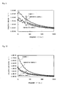
- the frequency dependences of the loss coefficient were measured by the center exciting method (steel plate of 10 x 200 x 0.8 mm and 12.35 g).
- the system configured with the oscillator of Type 2825, the amplifier of Type 2718, the vibrator of Type 4809, and the acceleration sensor of Type 8001 (all manufactured by B&K Co.) was used, and the personal computer was used to control each of the instruments.
- the damping materials of example 2 to example 4 exhibit loss coefficients more than twice as high as that of the damping material of comparative example 3 in a low frequency range of approximately 60 Hz to approximately 500 Hz, and thereby the effect of the present invention could be demonstrated.
- damping materials of example 2 to example 4 exhibit larger loss coefficients as the aspect ratio of the cellulose fiber of the piezoelectric fiber becomes larger, that is, in the order of example 4, example 3, and example 2, in the low frequency range of approximately 60 Hz to approximately 500 Hz.
Landscapes
- Engineering & Computer Science (AREA)
- General Engineering & Computer Science (AREA)
- Mechanical Engineering (AREA)
- Acoustics & Sound (AREA)
- Physics & Mathematics (AREA)
- Chemical & Material Sciences (AREA)
- Aviation & Aerospace Engineering (AREA)
- Multimedia (AREA)
- Health & Medical Sciences (AREA)
- Chemical Kinetics & Catalysis (AREA)
- Medicinal Chemistry (AREA)
- Polymers & Plastics (AREA)
- Organic Chemistry (AREA)
- Compositions Of Macromolecular Compounds (AREA)
Applications Claiming Priority (2)
| Application Number | Priority Date | Filing Date | Title |
|---|---|---|---|
| JP2013067226A JP6180148B2 (ja) | 2012-03-28 | 2013-03-27 | 複合制振材料 |
| PCT/JP2013/076310 WO2014155786A1 (ja) | 2013-03-27 | 2013-09-27 | 複合制振材料 |
Publications (2)
| Publication Number | Publication Date |
|---|---|
| EP2980443A1 true EP2980443A1 (de) | 2016-02-03 |
| EP2980443A4 EP2980443A4 (de) | 2016-11-09 |
Family
ID=51625712
Family Applications (1)
| Application Number | Title | Priority Date | Filing Date |
|---|---|---|---|
| EP13880324.2A Withdrawn EP2980443A4 (de) | 2013-03-27 | 2013-09-27 | Zusammengesetztes dämpfungsmaterial |
Country Status (5)
| Country | Link |
|---|---|
| US (1) | US20160040744A1 (de) |
| EP (1) | EP2980443A4 (de) |
| CN (1) | CN105190086A (de) |
| TW (1) | TW201437002A (de) |
| WO (1) | WO2014155786A1 (de) |
Families Citing this family (7)
| Publication number | Priority date | Publication date | Assignee | Title |
|---|---|---|---|---|
| US10446289B2 (en) | 2015-04-02 | 2019-10-15 | Cnh Industrial Canada, Ltd. | Method of providing electrical conductivity properties in biocomposite materials |
| JP6376167B2 (ja) * | 2016-03-31 | 2018-08-22 | マツダ株式会社 | 吸音材 |
| KR102070374B1 (ko) | 2016-12-28 | 2020-01-29 | 아사히 가세이 가부시키가이샤 | 셀룰로오스 함유 수지 조성물 및 셀룰로오스 제제 |
| CN108051870A (zh) * | 2017-11-29 | 2018-05-18 | 新马(安徽)制衣有限公司 | 一种抗干扰的检针方法 |
| KR102771063B1 (ko) * | 2018-12-31 | 2025-02-21 | 엘지디스플레이 주식회사 | 진동발생장치 및 이를 포함하는 디스플레이 장치 |
| US10951992B2 (en) | 2018-12-31 | 2021-03-16 | Lg Display Co., Ltd. | Vibration generating device and display apparatus including the same |
| JP6977942B2 (ja) * | 2019-12-04 | 2021-12-08 | 株式会社タイテックスジャパン | Cfrtp積層体及びその製造方法 |
Family Cites Families (12)
| Publication number | Priority date | Publication date | Assignee | Title |
|---|---|---|---|---|
| JPS6051750A (ja) * | 1983-08-30 | 1985-03-23 | Murata Mfg Co Ltd | 防振複合体 |
| JPH0685346A (ja) | 1992-09-04 | 1994-03-25 | Koa Oil Co Ltd | 圧電複合材料 |
| JP3192400B2 (ja) | 1997-01-10 | 2001-07-23 | 雅夫 住田 | 圧電分散型有機系複合制振材料 |
| US6002196A (en) * | 1997-01-10 | 1999-12-14 | Masao Sumita | Piezoelectric dispersion type organic damping composite |
| JPH10312191A (ja) | 1997-05-12 | 1998-11-24 | Tokai Rubber Ind Ltd | 高減衰材料 |
| US20020004543A1 (en) * | 2000-04-28 | 2002-01-10 | Carman Greg P. | Damping in composite materials through domain wall motion |
| JP2002069424A (ja) * | 2000-08-31 | 2002-03-08 | Masao Sumita | 有機ハイブリッド系制振材料、その製造方法およびそれに用いる制振改良剤 |
| US6566431B1 (en) * | 2000-09-25 | 2003-05-20 | Masao Sumita | Organohybrid-based damping material, method for producing the same, and method for damping using the same |
| DE10104604A1 (de) * | 2001-02-02 | 2002-08-22 | Daimler Chrysler Ag | Bauteil mit schwingungsdämpfenden Eigenschaften, Gemenge zur Herstellung des Bauteils, sowie Verfahren zur Herstellung eines derartigen Bauteils |
| US7029598B2 (en) * | 2002-06-19 | 2006-04-18 | Fuji Photo Film Co., Ltd. | Composite material for piezoelectric transduction |
| JP2010254777A (ja) * | 2009-04-23 | 2010-11-11 | Dainippon Printing Co Ltd | 制振層及び制振材 |
| JP2011099497A (ja) * | 2009-11-05 | 2011-05-19 | Titecs Japan:Kk | 複合制振材料、制振部材及び制振フィルム |
-
2013
- 2013-09-27 EP EP13880324.2A patent/EP2980443A4/de not_active Withdrawn
- 2013-09-27 WO PCT/JP2013/076310 patent/WO2014155786A1/ja not_active Ceased
- 2013-09-27 TW TW102135064A patent/TW201437002A/zh unknown
- 2013-09-27 CN CN201380075116.5A patent/CN105190086A/zh active Pending
-
2015
- 2015-09-28 US US14/867,492 patent/US20160040744A1/en not_active Abandoned
Also Published As
| Publication number | Publication date |
|---|---|
| CN105190086A (zh) | 2015-12-23 |
| US20160040744A1 (en) | 2016-02-11 |
| WO2014155786A1 (ja) | 2014-10-02 |
| EP2980443A4 (de) | 2016-11-09 |
| TW201437002A (zh) | 2014-10-01 |
Similar Documents
| Publication | Publication Date | Title |
|---|---|---|
| EP2980443A1 (de) | Zusammengesetztes dämpfungsmaterial | |
| Singh et al. | Flexible and robust piezoelectric polymer nanocomposites based energy harvesters | |
| Wu et al. | Entropy penalty-induced self-assembly in carbon black or carbon fiber filled polymer blends | |
| Litvinov et al. | EPDM− Carbon black interactions and the reinforcement mechanisms, as studied by low-resolution 1H NMR | |
| Shehzad et al. | Effects of carbon nanotubes aspect ratio on the qualitative and quantitative aspects of frequency response of electrical conductivity and dielectric permittivity in the carbon nanotube/polymer composites | |
| Han et al. | Self-poled poly (vinylidene fluoride)/MXene piezoelectric energy harvester with boosted power generation ability and the roles of crystalline orientation and polarized interfaces | |
| Wu et al. | Carbon black as a self-diagnosing probe to trace polymer dynamics in highly filled compositions | |
| Novikov et al. | Multifunctional elastic nanocomposites with extremely low concentrations of single-walled carbon nanotubes | |
| Xu et al. | Enhanced mechanical performance of segregated carbon nanotube/poly (lactic acid) composite for efficient electromagnetic interference shielding | |
| Wang et al. | Compressive relaxation of the stress and resistance for carbon nanotube filled silicone rubber composite | |
| Ferreira et al. | Effect of filler dispersion on the electromechanical response of epoxy/vapor-grown carbon nanofiber composites | |
| JP6180148B2 (ja) | 複合制振材料 | |
| Kumar et al. | Enhancement of electromechanical properties of natural rubber by adding barium titanate filler: An electro‐mechanical study | |
| US11015067B2 (en) | Slurry for flexible electrodes, and flexible electrode using same | |
| Li et al. | Tuning the structure and performance of bulk and porous vapor sensors based on co-continuous carbon nanotube-filled blends of poly (vinylidene fluoride) and polycarbonates by varying melt viscosity | |
| Prasad Sahoo et al. | Multiwalled carbon nanotube‐filled ethylene acrylic elastomer nanocomposites: influence of ionic liquids on the mechanical, dynamic mechanical, and dielectric properties | |
| Cho et al. | An extremely inexpensive, simple, and flexible carbon fiber electrode for tunable elastomeric piezo-resistive sensors and devices realized by LSTM RNN | |
| Amin et al. | Fabrication, mechanical, thermal, and electrical characterization of epoxy/silica composites for high-voltage insulation | |
| Arul et al. | Flexible electrospun PVDF/WO3 nanocomposite fibers for piezoelectric energy harvesting applications | |
| Mohebbi et al. | Polymer ferroelectret based on polypropylene foam: piezoelectric properties prediction using dynamic mechanical analysis | |
| Bello et al. | Universality and percolation in biodegradable poly (ε-caprolactone)/multiwalled carbon nanotube nanocomposites from broad band alternating and direct current conductivity at various temperatures | |
| Sanchez et al. | PVDF BaTiO3/carbon nanotubes ternary nanocomposites: Effect of nanofillers and processing | |
| Nakaramontri et al. | Enhancement of electrical conductivity and other related properties of epoxidized natural rubber/carbon nanotube composites by optimizing concentration of 3‐aminopropyltriethoxy silane | |
| Bhadra et al. | Development of a piezoelectric nanogenerator based on mesoporous silica/zinc oxide hybrid nanocomposite fibres | |
| Khosroshahi et al. | Preparation of Cross‐Linked Sponge With Piezoelectric Properties Based on Low Density Polyethylene/Poly (Ethylene‐Co‐Vinyl Acetate) and Barium Titanate: Relationship Between Mechanical Properties, and Cell Structure With Piezoelectric Coefficients |
Legal Events
| Date | Code | Title | Description |
|---|---|---|---|
| PUAI | Public reference made under article 153(3) epc to a published international application that has entered the european phase |
Free format text: ORIGINAL CODE: 0009012 |
|
| 17P | Request for examination filed |
Effective date: 20151027 |
|
| AK | Designated contracting states |
Kind code of ref document: A1 Designated state(s): AL AT BE BG CH CY CZ DE DK EE ES FI FR GB GR HR HU IE IS IT LI LT LU LV MC MK MT NL NO PL PT RO RS SE SI SK SM TR |
|
| AX | Request for extension of the european patent |
Extension state: BA ME |
|
| DAX | Request for extension of the european patent (deleted) | ||
| A4 | Supplementary search report drawn up and despatched |
Effective date: 20161012 |
|
| RIC1 | Information provided on ipc code assigned before grant |
Ipc: H01L 41/193 20060101ALI20161006BHEP Ipc: H01L 41/113 20060101ALI20161006BHEP Ipc: F16F 15/02 20060101AFI20161006BHEP Ipc: G10K 11/165 20060101ALI20161006BHEP |
|
| STAA | Information on the status of an ep patent application or granted ep patent |
Free format text: STATUS: THE APPLICATION IS DEEMED TO BE WITHDRAWN |
|
| 18D | Application deemed to be withdrawn |
Effective date: 20170509 |