EP2980448A1 - Dispositif d'engrenage à onde de déformation - Google Patents
Dispositif d'engrenage à onde de déformation Download PDFInfo
- Publication number
- EP2980448A1 EP2980448A1 EP14773038.6A EP14773038A EP2980448A1 EP 2980448 A1 EP2980448 A1 EP 2980448A1 EP 14773038 A EP14773038 A EP 14773038A EP 2980448 A1 EP2980448 A1 EP 2980448A1
- Authority
- EP
- European Patent Office
- Prior art keywords
- gear
- planetary gear
- internal
- internal gear
- strain wave
- Prior art date
- Legal status (The legal status is an assumption and is not a legal conclusion. Google has not performed a legal analysis and makes no representation as to the accuracy of the status listed.)
- Withdrawn
Links
Images



Classifications
-
- F—MECHANICAL ENGINEERING; LIGHTING; HEATING; WEAPONS; BLASTING
- F16—ENGINEERING ELEMENTS AND UNITS; GENERAL MEASURES FOR PRODUCING AND MAINTAINING EFFECTIVE FUNCTIONING OF MACHINES OR INSTALLATIONS; THERMAL INSULATION IN GENERAL
- F16H—GEARING
- F16H49/00—Other gearings
- F16H49/001—Wave gearings, e.g. harmonic drive transmissions
-
- F—MECHANICAL ENGINEERING; LIGHTING; HEATING; WEAPONS; BLASTING
- F16—ENGINEERING ELEMENTS AND UNITS; GENERAL MEASURES FOR PRODUCING AND MAINTAINING EFFECTIVE FUNCTIONING OF MACHINES OR INSTALLATIONS; THERMAL INSULATION IN GENERAL
- F16H—GEARING
- F16H49/00—Other gearings
- F16H49/001—Wave gearings, e.g. harmonic drive transmissions
- F16H2049/003—Features of the flexsplines therefor
-
- F—MECHANICAL ENGINEERING; LIGHTING; HEATING; WEAPONS; BLASTING
- F16—ENGINEERING ELEMENTS AND UNITS; GENERAL MEASURES FOR PRODUCING AND MAINTAINING EFFECTIVE FUNCTIONING OF MACHINES OR INSTALLATIONS; THERMAL INSULATION IN GENERAL
- F16H—GEARING
- F16H49/00—Other gearings
- F16H2049/006—Wave generators producing a non-elliptical shape of flexsplines, i.e. with a qualified different shape than elliptical
-
- F—MECHANICAL ENGINEERING; LIGHTING; HEATING; WEAPONS; BLASTING
- F16—ENGINEERING ELEMENTS AND UNITS; GENERAL MEASURES FOR PRODUCING AND MAINTAINING EFFECTIVE FUNCTIONING OF MACHINES OR INSTALLATIONS; THERMAL INSULATION IN GENERAL
- F16H—GEARING
- F16H57/00—General details of gearing
- F16H57/12—Arrangements for adjusting or for taking-up backlash not provided for elsewhere
- F16H2057/126—Self-adjusting during operation, e.g. by a spring
Definitions
- the present invention relates to a strain wave gearing apparatus and, in particular, to a strain wave gearing apparatus suitable for a so-called flat type structure.
- An existing flat type strain wave gearing apparatus is equipped with a rigid first internal gear, a rigid second internal gear arranged side by side with the first internal gear, a flexible planetary gear arranged on the inner peripheral side of the first and second internal gears and deflected in the radial direction so that a swollen portion thereof is brought into mesh with the first and second internal gears, and a wave generator fitted into the flexible planetary gear and configured to deflect the flexible planetary gear.
- the overall configuration is compact, and the flexible planetary gear is of a simple cylindrical configuration, so that no excessive stress is applied during rotation, making it advantageously possible to maintain a sufficient configuration retainability while maintaining flexibility.
- Japanese Laid-Open Patent Disclosure 1 JP-A-hei 2-221740
- Japanese Laid-Open Patent Disclosure 2 JP-A-2009-156462
- the strain wave gearing apparatus requires no backlash for the mesh-engagement between the gears; when used in a robot arm or the like, it is necessary to enhance the stopping accuracy, so that there is a demand for realizing a non-backlash mesh-engagement.
- the flexible planetary gear is cylindrical, so that such a pre-load as in the case of the cup-shaped structure is not to be expected.
- the Disclosure 1 proposes the formation of a large deflected portion through enhancement of the degree of ellipticity of the flexible planetary gear to realize a non-backlash mesh-engagement by realizing the pre-load of this deflected portion.
- a large deflected portion is forcibly formed, so that when an abrupt fluctuation in torque is generated, jumping is likely to occur.
- this structure is obviously inferior to the cup-shaped one also in terms of the backlash improving effect.
- the Disclosure 2 proposes, in contrast to the flat type structure, the realization of a non-backlash mesh-engagement through enhancement of the tooth shape precision. This proposal, however, is not realistic since it involves an excessive burden in terms of the gear manufacturing.
- the present invention has been made in view of the above problems in the prior art; it is an object of the present invention to provide a novel and useful strain wave gearing apparatus which can utilize the advantage in shape of the flat type apparatus as it is and which can realize an ideal non-backlash mesh-engagement without involving high dimensional precision or any special adjustment mechanism.
- the present inventor has found out that, by making the base portion of an internal gear elastic, the internal gear elastically receives an external gear to realize an ideal non-backlash mesh-engagement between the two gears, and that it is possible to prevent permanent deformation of the internal gear through mitigation of the wear thereof, making it possible to chronologically secure the above-mentioned non-backlash mesh-engagement, thus completing the present invention.
- a strain wave gearing apparatus including; a first internal gear, a second internal gear arranged side by side with the first internal gear, a flexible planetary gear arranged on the inner peripheral side of the first and second internal gears and deflected in the radial direction to be partially brought into mesh with the first and second internal gears, and a wave generator arranged on the inner side of the flexible planetary gear and configured to deflect the flexible planetary gear while continuously deforming the same through rotation, with a relative rotation being generated between the first internal gear and the second internal gear in accordance with a difference in number of teeth therebetween, wherein the first internal gear has an elastic base portion on the inner side of which is formed an inner teeth, and a rigid mounting portion connected to the base portion in a cantilever-like fashion, the second internal gear has an elastic base portion on the inner side of which is formed an inner teeth, and a rigid mounting portion connected to the base portion in a cantilever-like fashion, and the relative movement in the axial direction of
- a strain wave gearing apparatus in the first aspect, wherein the first and second internal gears are formed by thin-walled members.
- a strain wave gearing apparatus in the second aspect, wherein a back-up ring is arranged on the outer peripheral side of the first and second internal gears.
- a strain wave gearing apparatus in the second or third aspect, wherein the first and second internal gears consist of conical gears, and the flexible planetary gear consists of a biconical gear; and both tapered surface sides of the flexible planetary gear are respectively held by the internal gear sides to constrain relative movement in the axial direction.
- a strain wave gearing apparatus in one of the first to fourth aspects, wherein the wave generator has three or more mesh-engagement correspondence protrusions protruding outwardly to bring the first and second internal gears into mesh with the flexible planetary gear.
- strain wave gearing apparatus of the present invention it is possible to utilize the merit in shape of the flat type structure, and to realize an ideal non-backlash mesh-engagement without involving high dimensional precision and any special adjustment mechanism.
- a strain wave gearing apparatus 1 according to the first embodiment of the present invention will be described with reference to the drawings.
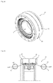
- this strain wave gearing apparatus 1 is equipped with a stationary internal gear 3, a rotary internal gear 11, a flexible planetary gear 19, and a wave generator 27; all of these components are formed of a metal material.
- a base portion 5 of the stationary internal gear 3 is generally substantially cylindrical; its contour on the inner peripheral side is formed so as to be conical in sectional view; and inner teeth 7 are formed on the tapered surface on the inner peripheral side thereof to constitute a conical internal gear.
- the base portion 5 is thin-walled, and the base portion 5 as a whole is elastic.
- a rigid mounting portion 9 is mounted to the divergent side end portion of the base portion 5.
- the rotary internal gear 11 also has a base portion 13, inner teeth 15, and a mounting portion 17 formed in the same manner as those of the stationary internal gear 3.
- the number of teeth of the rotary internal gear 11 is smaller than that of the stationary internal gear 3 by three (minus three).
- the base portions 5 and 13 of the internal gears 3 and 11 are substantially of the same configuration, so that the above difference in the number of teeth is realized through difference in tooth width and tooth length.
- a base portion 21 of the flexible planetary gear 19 is substantially cylindrical as a whole; however, its outer peripheral side contour is formed so as to be biconical in sectional view, and outer teeth 23 and 25 are formed on the outer peripheral tapered surface of the base portion 21 to constitute a biconical gear.
- the flexible planetary gear 19 is thin-walled, and elastic as a whole, and is configured to be deflected in conformity with pressure from the inner and outer peripheral sides.
- the wave generator 27 is equipped with a cam portion 29 of a substantially triangular outer contour, and a strain wave bearing 31 fitted onto the cam portion 29, with the hollow portion of the cam portion 29 constituting a connecting portion for the rotation shaft (not shown) of a motor.
- the strain wave bearing 31 has a plurality of balls 35 retained by a retainer 33, an inner ring 37, and an outer ring 39.
- the inner ring 37 is fixed to the outer periphery of the cam portion 29, and the outer ring 39 is fit-engaged with the inner peripheral side of the flexible planetary gear 19.
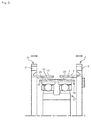
- the strain wave gearing apparatus 1 is formed through the combination of the above members; as shown in Fig. 3 , the stationary internal gear 3 and the rotary internal gear 11 are arranged side by side, and the flexible planetary gear 19 is arranged on the inner peripheral side thereof; the inner teeth 7 of the stationary internal gear 3 are in mesh with the outer teeth 23 of the flexible planetary gear 19, and the inner teeth 15 of the rotary internal gear 11 are in mesh with the outer teeth 25 of the flexible planetary gear 19.
- the wave generator 27 is fitted into the flexible planetary gear 19.
- the cam portion 29 of the wave generator 27 is substantially of a triangular outer peripheral contour and has three apex portions 30 constituting mesh-engagement correspondence protrusions 30, so that the flexible planetary gear 19 greatly protrudes radially outwards at the three portions, with the corresponding portions 30C being in mesh with the internal gears 3 and 11.
- the base portion 5 with the inner teeth 7 is, so to speak, connected to the rigid mounting portion 9 in a cantilever-like fashion; since the entire base portion 5 is elastic, the deflection of the outwardly protruding portions of the flexible planetary gear 19 side are elastically absorbed at the mesh-engagement portions, thereby eliminating backlash.
- the rotary internal gear 11 side also provides a similar action.
- the base portions 5 and 13 of the internal gears 3 and 11 are deflectable; with the convergent sides of the tapered surfaces of the base portions 5 and 13 being opposite each other, they are arranged on the outer side of the biconical tapered surface of the flexible planetary gear 19.
- the stationary internal gear 3 and the rotary internal gear 11 are brought sufficiently close to each other from both axial ends, whereby it is possible to constrain relative axial displacement, with the gap being minimized.
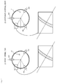
- Fig. 6(1) shows the mesh-engagement state prior to the movement; in this case, the conical effect cannot be utilized to the utmost, and the pre-load is small, with the deflection amount being so much the smaller.
- Fig. 6(2) shows the mesh-engagement state after the movement; under this constraint state, when the flexible planetary gear 19 rotates, and the swollen correspondence portion 30C comes around, the stationary internal gear 3 and the rotary internal gear 11, which have the elastic base portions 5 and 13, are deflected as indicated by the arrows, making it possible to apply a pre-load to the mesh-engagement portions between themselves and the outer teeth 23 of the flexible planetary gear 19.
- the magnitude of the pre-load can be optimized through adjustment of the axial movement amount. This pre-load helps to further diminish backlash.
- the balls 35 of the flexible planetary gear 19 revolve along the stationary internal gear 3 while rotating, and, while continuously deforming the flexible planetary gear 19, the mesh-engagement position between the stationary internal gear 3 and the flexible planetary gear 19, and the mesh-engagement position between the rotary internal gear 11 and the flexible planetary gear 19, are moved in the circumferential direction.
- the flexible planetary gear 19 functions as a reverse idler shaft, and relative rotation is generated in accordance with the difference in the number of teeth, with decelerated rotation being output to the rotary internal gear 11 side.
- the inner configuration of the internal gears 3 and 11 is conical, and the outer configuration of the flexible planetary gear 19 is conical, so that the mesh-engagement is effected through point contact; however, since both the base portions 5 and 13 are elastic, the point contact area is larger as compared with the case where one of them is rigid. Further, the flexible planetary gear 19 protrudes in a triangular form to be mesh-engaged with the internal gears 3 and 11 at three portions.
- a strain wave gearing apparatus 41 according to the second embodiment of the present invention will be described with reference to the drawings.
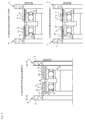
- annular back-up rings 43 and 45 are added to the strain wave apparatus 1.
- One axial end of the back-up ring 43 is connected to the mounting portion 9 of the stationary internal gear 3, and it surrounds the base portion 5 from the outer peripheral side with a slight gap therebetween; and one axial end of the back-up ring 45 is connected to the mounting portion 17 of the rotary internal gear 11, and it surrounds the base portion 13 from the outer peripheral side with a slight gap therebetween.
- the strain wave bearing may employ runners.
- the flexible planetary gear it is possible to change the number of mesh-engagement portions through a change in the configuration of the cam portion, so that the number may be set to an arbitrary number of two or more according to use.
- the two gears of the biconical gear may be of the same tapered configuration or of the same gear design; further, the bottom surfaces of the two cones may not directly face each other but through the intermediation of a spacer.
- 1 ... strain wave gearing apparatus (first embodiment), 3 ... stationary internal gear, 5 ... base portion, 7 ... inner teeth, 9 ... mounting portion, 11 ... rotary internal gear, 13 ... base portion, 15 ... inner teeth, 17 ... mounting portion, 19 ... flexible planetary gear, 21 ... base portion, 23, 25 ... outer teeth, 27 ... wave generator, 29 ... cam portion, 30 ... mesh-engagement correspondence protrusion, 31 ... strain wave bearing, 33 ... retainer, 35 ... ball, 37 ... inner ring, 39 ... outer ring, 41 ... strain wave gearing apparatus (second embodiment), 43, 45 ... back-up ring.
Landscapes
- Engineering & Computer Science (AREA)
- General Engineering & Computer Science (AREA)
- Mechanical Engineering (AREA)
- Retarders (AREA)
Applications Claiming Priority (2)
| Application Number | Priority Date | Filing Date | Title |
|---|---|---|---|
| JP2013065367A JP6030981B2 (ja) | 2013-03-27 | 2013-03-27 | 波動歯車装置 |
| PCT/JP2014/001696 WO2014156118A1 (fr) | 2013-03-27 | 2014-03-25 | Dispositif d'engrenage à onde de déformation |
Publications (2)
| Publication Number | Publication Date |
|---|---|
| EP2980448A1 true EP2980448A1 (fr) | 2016-02-03 |
| EP2980448A4 EP2980448A4 (fr) | 2016-10-05 |
Family
ID=51623131
Family Applications (1)
| Application Number | Title | Priority Date | Filing Date |
|---|---|---|---|
| EP14773038.6A Withdrawn EP2980448A4 (fr) | 2013-03-27 | 2014-03-25 | Dispositif d'engrenage à onde de déformation |
Country Status (8)
| Country | Link |
|---|---|
| US (1) | US9822864B2 (fr) |
| EP (1) | EP2980448A4 (fr) |
| JP (1) | JP6030981B2 (fr) |
| KR (1) | KR102148521B1 (fr) |
| CN (1) | CN105074272B (fr) |
| HK (1) | HK1214853A1 (fr) |
| TW (1) | TWI623695B (fr) |
| WO (1) | WO2014156118A1 (fr) |
Cited By (3)
| Publication number | Priority date | Publication date | Assignee | Title |
|---|---|---|---|---|
| EP3279512A1 (fr) * | 2016-08-05 | 2018-02-07 | Hamilton Sundstrand Corporation | Cannelure flexible jointe pour commande harmonique de composé |
| DE102017126527A1 (de) * | 2016-11-16 | 2018-05-17 | Schaeffler Technologies AG & Co. KG | Wellgetriebe |
| DE102018116255B4 (de) | 2017-09-27 | 2023-11-09 | Sumitomo Heavy Industries, Ltd. | Getriebevorrichtung des Biegeeingrifftyps |
Families Citing this family (24)
| Publication number | Priority date | Publication date | Assignee | Title |
|---|---|---|---|---|
| JP6218690B2 (ja) * | 2014-07-23 | 2017-10-25 | 株式会社ハーモニック・ドライブ・システムズ | デュアルタイプの波動歯車装置 |
| JP6338538B2 (ja) * | 2015-02-03 | 2018-06-06 | 住友重機械工業株式会社 | 撓み噛合い式歯車装置 |
| CA2927596A1 (fr) * | 2015-04-20 | 2016-10-20 | Nabors Lux Finance 2 Sarl | Transmission harmonique |
| US20160305528A1 (en) * | 2015-04-20 | 2016-10-20 | Nabors Lux Finance 2 Sarl | Harmonic Gear Drive |
| TWI572796B (zh) * | 2015-05-15 | 2017-03-01 | Harmonic gear differential gearbox | |
| DE102015109426A1 (de) * | 2015-06-12 | 2016-12-15 | Ovalo Gmbh | Radial bauraumsparendes Spannungswellengetriebe |
| JP6400200B2 (ja) * | 2015-07-07 | 2018-10-03 | 株式会社ハーモニック・ドライブ・システムズ | 波動歯車装置および波動発生器 |
| JP6644447B2 (ja) * | 2015-12-11 | 2020-02-12 | 株式会社ハーモニック・ドライブ・システムズ | フラット型波動歯車装置 |
| CN107795662B (zh) * | 2016-08-31 | 2020-06-19 | 比亚迪股份有限公司 | 用于谐波减速器的刚轮、谐波减速器以及机器人 |
| US10539210B2 (en) * | 2016-10-13 | 2020-01-21 | Superturbo Technologies, Inc. | Angular contact ball ramps for driven turbocharger |
| DE102016220919A1 (de) * | 2016-10-25 | 2018-04-26 | Schaeffler Technologies AG & Co. KG | Verstellgetriebeanordnung für ein Fahrzeug, Fahrzeug mit der Verstellgetriebeanordnung sowie Verfahren zur Montage der Verstellgetriebeanordnung |
| US10337561B2 (en) * | 2016-12-15 | 2019-07-02 | Boston Dynamics, Inc. | Transmission with integrated overload protection for a legged robot |
| CN110177958A (zh) * | 2017-01-21 | 2019-08-27 | 谐波传动系统有限公司 | 波动齿轮装置 |
| JP6904004B2 (ja) * | 2017-03-30 | 2021-07-14 | セイコーエプソン株式会社 | ロボットおよび歯車装置 |
| KR102185296B1 (ko) * | 2017-04-28 | 2020-12-01 | 가부시키가이샤 하모닉 드라이브 시스템즈 | 파동기어장치 및 파동발생기 |
| NO344461B1 (no) | 2017-07-06 | 2019-12-23 | Well Conveyor As | Trekkeverktøy benyttet i et borehull og/eller rørledning og en drivmodul for et trekkeverktøy |
| EP3719349B1 (fr) * | 2017-11-29 | 2025-04-23 | Harmonic Drive Systems Inc. | Dispositif d'engrenage à ondes |
| US10655711B2 (en) | 2018-04-06 | 2020-05-19 | Superturbo Technologies, Inc. | Single angular contact ball ramp for driven turbocharger |
| CN109737196A (zh) * | 2019-03-15 | 2019-05-10 | 苏州绿的谐波传动科技股份有限公司 | 一种高次频的精密谐波减速器 |
| JP7221132B2 (ja) * | 2019-05-24 | 2023-02-13 | 住友重機械工業株式会社 | 撓み噛合い式歯車装置 |
| JP7585096B2 (ja) * | 2021-03-05 | 2024-11-18 | ナブテスコ株式会社 | 波動歯車装置の製造方法 |
| CN114017486B (zh) * | 2021-11-25 | 2023-07-21 | 江苏科技大学 | 一种机器人关节多传动比的传动装置 |
| JP2024152380A (ja) * | 2023-04-14 | 2024-10-25 | 住友重機械工業株式会社 | 撓み噛合い式歯車装置 |
| CN121184533B (zh) * | 2025-11-26 | 2026-02-24 | 江苏旭泉电机股份有限公司 | 具有柔性圆柱随轮的不偏心单多齿差双啮合行星轮减速器 |
Family Cites Families (12)
| Publication number | Priority date | Publication date | Assignee | Title |
|---|---|---|---|---|
| JP2796109B2 (ja) | 1989-02-23 | 1998-09-10 | 株式会社ハーモニック・ドライブ・システムズ | 波動歯車の波動発生器 |
| JPH05141485A (ja) * | 1991-11-16 | 1993-06-08 | Harmonic Drive Syst Ind Co Ltd | 低減速比を有するコツプ型波動歯車装置 |
| JPH05141486A (ja) * | 1991-11-16 | 1993-06-08 | Harmonic Drive Syst Ind Co Ltd | 低減速比を有するフラツト型波動歯車装置 |
| US5937710A (en) * | 1998-04-06 | 1999-08-17 | Teijin Seiki Boston, Inc | Harmonic-drive transmission |
| JP2000120811A (ja) * | 1998-08-12 | 2000-04-28 | Teijin Seiki Co Ltd | 撓み噛み合い式減速機 |
| US7306535B2 (en) * | 2004-06-29 | 2007-12-11 | Delphi Technologies, Inc. | Vehicle steering device and method |
| JP4877837B2 (ja) | 2007-12-04 | 2012-02-15 | 株式会社ハーモニック・ドライブ・システムズ | フラット型波動歯車装置の同歯数側歯車の歯形設定方法 |
| JP4948479B2 (ja) * | 2008-06-26 | 2012-06-06 | 株式会社ハーモニック・ドライブ・システムズ | 複合型波動歯車減速機 |
| JP2010014207A (ja) * | 2008-07-03 | 2010-01-21 | Kikuchi Haguruma Kk | 駆動装置 |
| JP2010151196A (ja) * | 2008-12-24 | 2010-07-08 | Kikuchi Haguruma Kk | 減速装置 |
| JP5256249B2 (ja) * | 2010-06-18 | 2013-08-07 | 住友重機械工業株式会社 | 撓み噛合い式歯車装置 |
| JP2012167770A (ja) * | 2011-02-16 | 2012-09-06 | Daiken Co Ltd | 外歯歯車の製造方法、減速機、及びクラッチ |
-
2013
- 2013-03-27 JP JP2013065367A patent/JP6030981B2/ja active Active
-
2014
- 2014-03-25 US US14/773,607 patent/US9822864B2/en not_active Expired - Fee Related
- 2014-03-25 EP EP14773038.6A patent/EP2980448A4/fr not_active Withdrawn
- 2014-03-25 KR KR1020157024535A patent/KR102148521B1/ko active Active
- 2014-03-25 WO PCT/JP2014/001696 patent/WO2014156118A1/fr not_active Ceased
- 2014-03-25 HK HK16102755.3A patent/HK1214853A1/zh unknown
- 2014-03-25 CN CN201480016375.5A patent/CN105074272B/zh active Active
- 2014-03-26 TW TW103111241A patent/TWI623695B/zh not_active IP Right Cessation
Cited By (4)
| Publication number | Priority date | Publication date | Assignee | Title |
|---|---|---|---|---|
| EP3279512A1 (fr) * | 2016-08-05 | 2018-02-07 | Hamilton Sundstrand Corporation | Cannelure flexible jointe pour commande harmonique de composé |
| US10584782B2 (en) | 2016-08-05 | 2020-03-10 | Hamilton Sundstrand Corporation | Joined flex spline for compound harmonic drive |
| DE102017126527A1 (de) * | 2016-11-16 | 2018-05-17 | Schaeffler Technologies AG & Co. KG | Wellgetriebe |
| DE102018116255B4 (de) | 2017-09-27 | 2023-11-09 | Sumitomo Heavy Industries, Ltd. | Getriebevorrichtung des Biegeeingrifftyps |
Also Published As
| Publication number | Publication date |
|---|---|
| WO2014156118A1 (fr) | 2014-10-02 |
| US20160061308A1 (en) | 2016-03-03 |
| TW201510388A (zh) | 2015-03-16 |
| TWI623695B (zh) | 2018-05-11 |
| KR20150138185A (ko) | 2015-12-09 |
| JP6030981B2 (ja) | 2016-11-24 |
| KR102148521B1 (ko) | 2020-08-26 |
| JP2014190396A (ja) | 2014-10-06 |
| US9822864B2 (en) | 2017-11-21 |
| EP2980448A4 (fr) | 2016-10-05 |
| HK1214853A1 (zh) | 2016-08-05 |
| CN105074272A (zh) | 2015-11-18 |
| CN105074272B (zh) | 2018-02-13 |
Similar Documents
| Publication | Publication Date | Title |
|---|---|---|
| US9822864B2 (en) | Strain wave gearing apparatus | |
| US9377096B2 (en) | Wave generator of strain wave gearing | |
| JP5064300B2 (ja) | 波動歯車式直動機構 | |
| CN103717940B (zh) | 带复合滚动轴承的内齿齿轮单元及波动齿轮装置 | |
| KR101616518B1 (ko) | 파동 기어 장치의 파동 발생기 | |
| EP3388713B1 (fr) | Dispositif d'engrenages à ondes de déformation plat | |
| WO2014203295A1 (fr) | Support de palier, mécanisme de palier et dispositif d'engrenages à ondes de déformation | |
| US20210140529A1 (en) | Strain wave gearing | |
| JP2019044936A (ja) | 変速機 | |
| JP6192580B2 (ja) | 撓み噛合い式歯車装置 | |
| US11841071B2 (en) | Flat strain wave gearing | |
| JP2017223246A (ja) | 波動歯車伝達装置 | |
| JP2017207193A (ja) | トラクション減速機および電動機付き減速機 | |
| KR20160122023A (ko) | 하모닉 드라이브 | |
| KR20160001343A (ko) | 하모닉 감속기 | |
| CN106286716A (zh) | 使用了内切凸轮和圆筒小齿轮的动力传递装置 | |
| JP2024092894A (ja) | 内接噛合遊星歯車装置及びロボット用関節装置 | |
| JP2011196423A (ja) | ロボットとそれに用いられるアクチュエータおよび偏平型波動歯車装置 | |
| JP2018076887A (ja) | 波動歯車装置 | |
| JPH03265742A (ja) | 撓み噛合い式歯車装置 | |
| JP2019015365A (ja) | 減速機 |
Legal Events
| Date | Code | Title | Description |
|---|---|---|---|
| PUAI | Public reference made under article 153(3) epc to a published international application that has entered the european phase |
Free format text: ORIGINAL CODE: 0009012 |
|
| 17P | Request for examination filed |
Effective date: 20150903 |
|
| AK | Designated contracting states |
Kind code of ref document: A1 Designated state(s): AL AT BE BG CH CY CZ DE DK EE ES FI FR GB GR HR HU IE IS IT LI LT LU LV MC MK MT NL NO PL PT RO RS SE SI SK SM TR |
|
| AX | Request for extension of the european patent |
Extension state: BA ME |
|
| DAX | Request for extension of the european patent (deleted) | ||
| A4 | Supplementary search report drawn up and despatched |
Effective date: 20160906 |
|
| RIC1 | Information provided on ipc code assigned before grant |
Ipc: F16H 57/12 20060101ALN20160831BHEP Ipc: F16H 1/32 20060101AFI20160831BHEP |
|
| GRAP | Despatch of communication of intention to grant a patent |
Free format text: ORIGINAL CODE: EPIDOSNIGR1 |
|
| RIC1 | Information provided on ipc code assigned before grant |
Ipc: F16H 57/12 20060101ALN20170228BHEP Ipc: F16H 1/32 20060101AFI20170228BHEP |
|
| INTG | Intention to grant announced |
Effective date: 20170323 |
|
| STAA | Information on the status of an ep patent application or granted ep patent |
Free format text: STATUS: THE APPLICATION IS DEEMED TO BE WITHDRAWN |
|
| 18D | Application deemed to be withdrawn |
Effective date: 20170803 |