EP2980896A1 - Électrode pour dispositif de stockage d'électricité et dispositif de stockage d'électricité utilisant ladite électrode - Google Patents
Électrode pour dispositif de stockage d'électricité et dispositif de stockage d'électricité utilisant ladite électrode Download PDFInfo
- Publication number
- EP2980896A1 EP2980896A1 EP14772631.9A EP14772631A EP2980896A1 EP 2980896 A1 EP2980896 A1 EP 2980896A1 EP 14772631 A EP14772631 A EP 14772631A EP 2980896 A1 EP2980896 A1 EP 2980896A1
- Authority
- EP
- European Patent Office
- Prior art keywords
- power storage
- storage device
- electrode
- sulfide
- composite material
- Prior art date
- Legal status (The legal status is an assumption and is not a legal conclusion. Google has not performed a legal analysis and makes no representation as to the accuracy of the status listed.)
- Withdrawn
Links
- 238000003860 storage Methods 0.000 title claims abstract description 85
- 239000002131 composite material Substances 0.000 claims abstract description 42
- -1 sulfide compound Chemical class 0.000 claims abstract description 35
- 239000007772 electrode material Substances 0.000 claims abstract description 25
- UCKMPCXJQFINFW-UHFFFAOYSA-N Sulphide Chemical compound [S-2] UCKMPCXJQFINFW-UHFFFAOYSA-N 0.000 claims abstract description 24
- 229920000620 organic polymer Polymers 0.000 claims abstract description 15
- 239000011230 binding agent Substances 0.000 claims abstract description 10
- 239000003792 electrolyte Substances 0.000 claims description 19
- 229920001577 copolymer Polymers 0.000 claims description 15
- 238000000605 extraction Methods 0.000 claims description 13
- 238000003780 insertion Methods 0.000 claims description 13
- 230000037431 insertion Effects 0.000 claims description 13
- 150000002500 ions Chemical class 0.000 claims description 13
- 150000001875 compounds Chemical class 0.000 claims description 11
- 229910052751 metal Inorganic materials 0.000 claims description 11
- 239000002184 metal Substances 0.000 claims description 10
- 229920000642 polymer Polymers 0.000 claims description 9
- 239000012986 chain transfer agent Substances 0.000 claims description 7
- 238000006116 polymerization reaction Methods 0.000 claims description 5
- 150000003573 thiols Chemical group 0.000 claims description 4
- BIGYLAKFCGVRAN-UHFFFAOYSA-N 1,3,4-thiadiazolidine-2,5-dithione Chemical compound S=C1NNC(=S)S1 BIGYLAKFCGVRAN-UHFFFAOYSA-N 0.000 claims description 3
- NINIDFKCEFEMDL-UHFFFAOYSA-N Sulfur Chemical compound [S] NINIDFKCEFEMDL-UHFFFAOYSA-N 0.000 claims description 2
- GLNWILHOFOBOFD-UHFFFAOYSA-N lithium sulfide Chemical compound [Li+].[Li+].[S-2] GLNWILHOFOBOFD-UHFFFAOYSA-N 0.000 claims description 2
- 229910052717 sulfur Inorganic materials 0.000 claims description 2
- 239000011593 sulfur Substances 0.000 claims description 2
- 125000003396 thiol group Chemical group [H]S* 0.000 claims description 2
- 150000007944 thiolates Chemical group 0.000 claims description 2
- WZRRRFSJFQTGGB-UHFFFAOYSA-N 1,3,5-triazinane-2,4,6-trithione Chemical compound S=C1NC(=S)NC(=S)N1 WZRRRFSJFQTGGB-UHFFFAOYSA-N 0.000 claims 1
- 230000009467 reduction Effects 0.000 abstract description 6
- 229920000767 polyaniline Polymers 0.000 description 25
- 239000008151 electrolyte solution Substances 0.000 description 23
- 239000000463 material Substances 0.000 description 19
- 239000000843 powder Substances 0.000 description 17
- PAYRUJLWNCNPSJ-UHFFFAOYSA-N Aniline Chemical compound NC1=CC=CC=C1 PAYRUJLWNCNPSJ-UHFFFAOYSA-N 0.000 description 16
- WEVYAHXRMPXWCK-UHFFFAOYSA-N Acetonitrile Chemical compound CC#N WEVYAHXRMPXWCK-UHFFFAOYSA-N 0.000 description 15
- OKTJSMMVPCPJKN-UHFFFAOYSA-N Carbon Chemical compound [C] OKTJSMMVPCPJKN-UHFFFAOYSA-N 0.000 description 12
- OKKJLVBELUTLKV-UHFFFAOYSA-N Methanol Chemical compound OC OKKJLVBELUTLKV-UHFFFAOYSA-N 0.000 description 12
- 239000007864 aqueous solution Substances 0.000 description 11
- 238000004519 manufacturing process Methods 0.000 description 11
- 238000000034 method Methods 0.000 description 11
- 239000000243 solution Substances 0.000 description 11
- 239000011149 active material Substances 0.000 description 10
- 230000008569 process Effects 0.000 description 10
- WHXSMMKQMYFTQS-UHFFFAOYSA-N Lithium Chemical compound [Li] WHXSMMKQMYFTQS-UHFFFAOYSA-N 0.000 description 9
- 229910052799 carbon Inorganic materials 0.000 description 9
- 229910052744 lithium Inorganic materials 0.000 description 9
- CSCPPACGZOOCGX-UHFFFAOYSA-N Acetone Chemical compound CC(C)=O CSCPPACGZOOCGX-UHFFFAOYSA-N 0.000 description 8
- 239000011148 porous material Substances 0.000 description 8
- 238000005259 measurement Methods 0.000 description 7
- 239000002904 solvent Substances 0.000 description 7
- 239000002253 acid Substances 0.000 description 6
- VNWKTOKETHGBQD-UHFFFAOYSA-N methane Chemical compound C VNWKTOKETHGBQD-UHFFFAOYSA-N 0.000 description 6
- 239000007787 solid Substances 0.000 description 6
- HBBGRARXTFLTSG-UHFFFAOYSA-N Lithium ion Chemical compound [Li+] HBBGRARXTFLTSG-UHFFFAOYSA-N 0.000 description 5
- 239000006258 conductive agent Substances 0.000 description 5
- WNAHIZMDSQCWRP-UHFFFAOYSA-N dodecane-1-thiol Chemical compound CCCCCCCCCCCCS WNAHIZMDSQCWRP-UHFFFAOYSA-N 0.000 description 5
- 229910001416 lithium ion Inorganic materials 0.000 description 5
- XLYOFNOQVPJJNP-UHFFFAOYSA-N water Substances O XLYOFNOQVPJJNP-UHFFFAOYSA-N 0.000 description 5
- XKRFYHLGVUSROY-UHFFFAOYSA-N Argon Chemical compound [Ar] XKRFYHLGVUSROY-UHFFFAOYSA-N 0.000 description 4
- BAPJBEWLBFYGME-UHFFFAOYSA-N Methyl acrylate Chemical compound COC(=O)C=C BAPJBEWLBFYGME-UHFFFAOYSA-N 0.000 description 4
- SECXISVLQFMRJM-UHFFFAOYSA-N N-Methylpyrrolidone Chemical compound CN1CCCC1=O SECXISVLQFMRJM-UHFFFAOYSA-N 0.000 description 4
- PXHVJJICTQNCMI-UHFFFAOYSA-N Nickel Chemical compound [Ni] PXHVJJICTQNCMI-UHFFFAOYSA-N 0.000 description 4
- FFBHFFJDDLITSX-UHFFFAOYSA-N benzyl N-[2-hydroxy-4-(3-oxomorpholin-4-yl)phenyl]carbamate Chemical compound OC1=C(NC(=O)OCC2=CC=CC=C2)C=CC(=C1)N1CCOCC1=O FFBHFFJDDLITSX-UHFFFAOYSA-N 0.000 description 4
- 239000003575 carbonaceous material Substances 0.000 description 4
- 238000010276 construction Methods 0.000 description 4
- 229910001496 lithium tetrafluoroborate Inorganic materials 0.000 description 4
- 239000000203 mixture Substances 0.000 description 4
- 239000003960 organic solvent Substances 0.000 description 4
- 239000007784 solid electrolyte Substances 0.000 description 4
- 238000003756 stirring Methods 0.000 description 4
- 229910000314 transition metal oxide Inorganic materials 0.000 description 4
- NLHHRLWOUZZQLW-UHFFFAOYSA-N Acrylonitrile Chemical compound C=CC#N NLHHRLWOUZZQLW-UHFFFAOYSA-N 0.000 description 3
- 229920000049 Carbon (fiber) Polymers 0.000 description 3
- KMTRUDSVKNLOMY-UHFFFAOYSA-N Ethylene carbonate Chemical compound O=C1OCCO1 KMTRUDSVKNLOMY-UHFFFAOYSA-N 0.000 description 3
- VYPSYNLAJGMNEJ-UHFFFAOYSA-N Silicium dioxide Chemical compound O=[Si]=O VYPSYNLAJGMNEJ-UHFFFAOYSA-N 0.000 description 3
- HEMHJVSKTPXQMS-UHFFFAOYSA-M Sodium hydroxide Chemical compound [OH-].[Na+] HEMHJVSKTPXQMS-UHFFFAOYSA-M 0.000 description 3
- 230000000052 comparative effect Effects 0.000 description 3
- 238000004090 dissolution Methods 0.000 description 3
- 239000002019 doping agent Substances 0.000 description 3
- 150000002739 metals Chemical class 0.000 description 3
- 239000004570 mortar (masonry) Substances 0.000 description 3
- 239000007800 oxidant agent Substances 0.000 description 3
- 239000002244 precipitate Substances 0.000 description 3
- RUOJZAUFBMNUDX-UHFFFAOYSA-N propylene carbonate Chemical compound CC1COC(=O)O1 RUOJZAUFBMNUDX-UHFFFAOYSA-N 0.000 description 3
- 150000003839 salts Chemical class 0.000 description 3
- 229910001220 stainless steel Inorganic materials 0.000 description 3
- 239000010935 stainless steel Substances 0.000 description 3
- DHKHKXVYLBGOIT-UHFFFAOYSA-N 1,1-Diethoxyethane Chemical compound CCOC(C)OCC DHKHKXVYLBGOIT-UHFFFAOYSA-N 0.000 description 2
- YEJRWHAVMIAJKC-UHFFFAOYSA-N 4-Butyrolactone Chemical compound O=C1CCCO1 YEJRWHAVMIAJKC-UHFFFAOYSA-N 0.000 description 2
- 102100027715 4-hydroxy-2-oxoglutarate aldolase, mitochondrial Human genes 0.000 description 2
- IJGRMHOSHXDMSA-UHFFFAOYSA-N Atomic nitrogen Chemical compound N#N IJGRMHOSHXDMSA-UHFFFAOYSA-N 0.000 description 2
- RYGMFSIKBFXOCR-UHFFFAOYSA-N Copper Chemical compound [Cu] RYGMFSIKBFXOCR-UHFFFAOYSA-N 0.000 description 2
- IAZDPXIOMUYVGZ-UHFFFAOYSA-N Dimethylsulphoxide Chemical compound CS(C)=O IAZDPXIOMUYVGZ-UHFFFAOYSA-N 0.000 description 2
- LFQSCWFLJHTTHZ-UHFFFAOYSA-N Ethanol Chemical compound CCO LFQSCWFLJHTTHZ-UHFFFAOYSA-N 0.000 description 2
- 101001081225 Homo sapiens 4-hydroxy-2-oxoglutarate aldolase, mitochondrial Proteins 0.000 description 2
- 101001109518 Homo sapiens N-acetylneuraminate lyase Proteins 0.000 description 2
- 102100022686 N-acetylneuraminate lyase Human genes 0.000 description 2
- 229910052782 aluminium Inorganic materials 0.000 description 2
- XAGFODPZIPBFFR-UHFFFAOYSA-N aluminium Chemical compound [Al] XAGFODPZIPBFFR-UHFFFAOYSA-N 0.000 description 2
- 150000001408 amides Chemical class 0.000 description 2
- 229910052786 argon Inorganic materials 0.000 description 2
- 239000003990 capacitor Substances 0.000 description 2
- 239000006229 carbon black Substances 0.000 description 2
- 235000019241 carbon black Nutrition 0.000 description 2
- 150000004649 carbonic acid derivatives Chemical class 0.000 description 2
- 239000003153 chemical reaction reagent Substances 0.000 description 2
- 229910052802 copper Inorganic materials 0.000 description 2
- 239000010949 copper Substances 0.000 description 2
- 150000002170 ethers Chemical class 0.000 description 2
- 239000004744 fabric Substances 0.000 description 2
- 239000011888 foil Substances 0.000 description 2
- 239000007789 gas Substances 0.000 description 2
- 238000002329 infrared spectrum Methods 0.000 description 2
- KWGKDLIKAYFUFQ-UHFFFAOYSA-M lithium chloride Chemical compound [Li+].[Cl-] KWGKDLIKAYFUFQ-UHFFFAOYSA-M 0.000 description 2
- NUJOXMJBOLGQSY-UHFFFAOYSA-N manganese dioxide Chemical compound O=[Mn]=O NUJOXMJBOLGQSY-UHFFFAOYSA-N 0.000 description 2
- 238000000691 measurement method Methods 0.000 description 2
- 229910052759 nickel Inorganic materials 0.000 description 2
- 150000002825 nitriles Chemical class 0.000 description 2
- 229910052757 nitrogen Inorganic materials 0.000 description 2
- 239000004745 nonwoven fabric Substances 0.000 description 2
- 239000003921 oil Substances 0.000 description 2
- 125000006353 oxyethylene group Chemical group 0.000 description 2
- 229910052710 silicon Inorganic materials 0.000 description 2
- 239000010703 silicon Substances 0.000 description 2
- 239000002002 slurry Substances 0.000 description 2
- 239000000126 substance Substances 0.000 description 2
- PXLYGWXKAVCTPX-UHFFFAOYSA-N 1,2,3,4,5,6-hexamethylidenecyclohexane Chemical compound C=C1C(=C)C(=C)C(=C)C(=C)C1=C PXLYGWXKAVCTPX-UHFFFAOYSA-N 0.000 description 1
- ZZXUZKXVROWEIF-UHFFFAOYSA-N 1,2-butylene carbonate Chemical compound CCC1COC(=O)O1 ZZXUZKXVROWEIF-UHFFFAOYSA-N 0.000 description 1
- 238000005160 1H NMR spectroscopy Methods 0.000 description 1
- OIFBSDVPJOWBCH-UHFFFAOYSA-N Diethyl carbonate Chemical compound CCOC(=O)OCC OIFBSDVPJOWBCH-UHFFFAOYSA-N 0.000 description 1
- XTHFKEDIFFGKHM-UHFFFAOYSA-N Dimethoxyethane Chemical compound COCCOC XTHFKEDIFFGKHM-UHFFFAOYSA-N 0.000 description 1
- IAZDPXIOMUYVGZ-WFGJKAKNSA-N Dimethyl sulfoxide Chemical compound [2H]C([2H])([2H])S(=O)C([2H])([2H])[2H] IAZDPXIOMUYVGZ-WFGJKAKNSA-N 0.000 description 1
- 229910000552 LiCF3SO3 Inorganic materials 0.000 description 1
- 229910013385 LiN(SO2C2F5)2 Inorganic materials 0.000 description 1
- 229910013406 LiN(SO2CF3)2 Inorganic materials 0.000 description 1
- 229910001290 LiPF6 Inorganic materials 0.000 description 1
- PWHULOQIROXLJO-UHFFFAOYSA-N Manganese Chemical compound [Mn] PWHULOQIROXLJO-UHFFFAOYSA-N 0.000 description 1
- CERQOIWHTDAKMF-UHFFFAOYSA-N Methacrylic acid Chemical class CC(=C)C(O)=O CERQOIWHTDAKMF-UHFFFAOYSA-N 0.000 description 1
- 239000004698 Polyethylene Substances 0.000 description 1
- 239000004642 Polyimide Substances 0.000 description 1
- 239000004743 Polypropylene Substances 0.000 description 1
- ATJFFYVFTNAWJD-UHFFFAOYSA-N Tin Chemical compound [Sn] ATJFFYVFTNAWJD-UHFFFAOYSA-N 0.000 description 1
- 239000006230 acetylene black Substances 0.000 description 1
- 150000001298 alcohols Chemical class 0.000 description 1
- 238000004458 analytical method Methods 0.000 description 1
- 238000000149 argon plasma sintering Methods 0.000 description 1
- 230000015572 biosynthetic process Effects 0.000 description 1
- 125000004432 carbon atom Chemical group C* 0.000 description 1
- 239000004917 carbon fiber Substances 0.000 description 1
- 239000002041 carbon nanotube Substances 0.000 description 1
- 229910021393 carbon nanotube Inorganic materials 0.000 description 1
- 230000008859 change Effects 0.000 description 1
- 238000006243 chemical reaction Methods 0.000 description 1
- 239000007795 chemical reaction product Substances 0.000 description 1
- 229920001940 conductive polymer Polymers 0.000 description 1
- 239000004020 conductor Substances 0.000 description 1
- 238000010908 decantation Methods 0.000 description 1
- IEJIGPNLZYLLBP-UHFFFAOYSA-N dimethyl carbonate Chemical compound COC(=O)OC IEJIGPNLZYLLBP-UHFFFAOYSA-N 0.000 description 1
- 125000002228 disulfide group Chemical group 0.000 description 1
- 239000012990 dithiocarbamate Substances 0.000 description 1
- 150000004659 dithiocarbamates Chemical class 0.000 description 1
- 238000003411 electrode reaction Methods 0.000 description 1
- 238000005516 engineering process Methods 0.000 description 1
- JBTWLSYIZRCDFO-UHFFFAOYSA-N ethyl methyl carbonate Chemical compound CCOC(=O)OC JBTWLSYIZRCDFO-UHFFFAOYSA-N 0.000 description 1
- 238000002474 experimental method Methods 0.000 description 1
- 239000000706 filtrate Substances 0.000 description 1
- 239000000446 fuel Substances 0.000 description 1
- 239000011521 glass Substances 0.000 description 1
- 229910002804 graphite Inorganic materials 0.000 description 1
- 239000010439 graphite Substances 0.000 description 1
- 230000006872 improvement Effects 0.000 description 1
- 239000011261 inert gas Substances 0.000 description 1
- 238000002347 injection Methods 0.000 description 1
- 239000007924 injection Substances 0.000 description 1
- 230000010220 ion permeability Effects 0.000 description 1
- 239000003273 ketjen black Substances 0.000 description 1
- 229910000625 lithium cobalt oxide Inorganic materials 0.000 description 1
- 229910001540 lithium hexafluoroarsenate(V) Inorganic materials 0.000 description 1
- 229910002102 lithium manganese oxide Inorganic materials 0.000 description 1
- 229910001486 lithium perchlorate Inorganic materials 0.000 description 1
- MHCFAGZWMAWTNR-UHFFFAOYSA-M lithium perchlorate Chemical compound [Li+].[O-]Cl(=O)(=O)=O MHCFAGZWMAWTNR-UHFFFAOYSA-M 0.000 description 1
- QSZMZKBZAYQGRS-UHFFFAOYSA-N lithium;bis(trifluoromethylsulfonyl)azanide Chemical compound [Li+].FC(F)(F)S(=O)(=O)[N-]S(=O)(=O)C(F)(F)F QSZMZKBZAYQGRS-UHFFFAOYSA-N 0.000 description 1
- BFZPBUKRYWOWDV-UHFFFAOYSA-N lithium;oxido(oxo)cobalt Chemical compound [Li+].[O-][Co]=O BFZPBUKRYWOWDV-UHFFFAOYSA-N 0.000 description 1
- VLXXBCXTUVRROQ-UHFFFAOYSA-N lithium;oxido-oxo-(oxomanganiooxy)manganese Chemical compound [Li+].[O-][Mn](=O)O[Mn]=O VLXXBCXTUVRROQ-UHFFFAOYSA-N 0.000 description 1
- 229910052748 manganese Inorganic materials 0.000 description 1
- 239000011572 manganese Substances 0.000 description 1
- 229910021645 metal ion Inorganic materials 0.000 description 1
- 239000007769 metal material Substances 0.000 description 1
- 238000012986 modification Methods 0.000 description 1
- 230000004048 modification Effects 0.000 description 1
- 230000007935 neutral effect Effects 0.000 description 1
- 239000011255 nonaqueous electrolyte Substances 0.000 description 1
- 230000003647 oxidation Effects 0.000 description 1
- 238000007254 oxidation reaction Methods 0.000 description 1
- VLTRZXGMWDSKGL-UHFFFAOYSA-M perchlorate Chemical compound [O-]Cl(=O)(=O)=O VLTRZXGMWDSKGL-UHFFFAOYSA-M 0.000 description 1
- HKOOXMFOFWEVGF-UHFFFAOYSA-N phenylhydrazine Chemical compound NNC1=CC=CC=C1 HKOOXMFOFWEVGF-UHFFFAOYSA-N 0.000 description 1
- 229940067157 phenylhydrazine Drugs 0.000 description 1
- 229920003229 poly(methyl methacrylate) Polymers 0.000 description 1
- 229920002627 poly(phosphazenes) Polymers 0.000 description 1
- 229920002239 polyacrylonitrile Polymers 0.000 description 1
- 229920000573 polyethylene Polymers 0.000 description 1
- 229920001223 polyethylene glycol Polymers 0.000 description 1
- 229920001721 polyimide Polymers 0.000 description 1
- 239000002861 polymer material Substances 0.000 description 1
- 229920000193 polymethacrylate Polymers 0.000 description 1
- 229920001155 polypropylene Polymers 0.000 description 1
- 229920001451 polypropylene glycol Polymers 0.000 description 1
- 229920002981 polyvinylidene fluoride Polymers 0.000 description 1
- 239000007774 positive electrode material Substances 0.000 description 1
- 238000002360 preparation method Methods 0.000 description 1
- 239000000047 product Substances 0.000 description 1
- FVSKHRXBFJPNKK-UHFFFAOYSA-N propionitrile Chemical compound CCC#N FVSKHRXBFJPNKK-UHFFFAOYSA-N 0.000 description 1
- 125000004151 quinonyl group Chemical group 0.000 description 1
- 239000011541 reaction mixture Substances 0.000 description 1
- 239000003507 refrigerant Substances 0.000 description 1
- 238000001226 reprecipitation Methods 0.000 description 1
- 229920005989 resin Polymers 0.000 description 1
- 239000011347 resin Substances 0.000 description 1
- 238000003786 synthesis reaction Methods 0.000 description 1
- 125000000101 thioether group Chemical group 0.000 description 1
- PQDJYEQOELDLCP-UHFFFAOYSA-N trimethylsilane Chemical compound C[SiH](C)C PQDJYEQOELDLCP-UHFFFAOYSA-N 0.000 description 1
- 239000012989 trithiocarbonate Substances 0.000 description 1
- 238000001291 vacuum drying Methods 0.000 description 1
Images
Classifications
-
- H—ELECTRICITY
- H01—ELECTRIC ELEMENTS
- H01M—PROCESSES OR MEANS, e.g. BATTERIES, FOR THE DIRECT CONVERSION OF CHEMICAL ENERGY INTO ELECTRICAL ENERGY
- H01M4/00—Electrodes
- H01M4/02—Electrodes composed of, or comprising, active material
- H01M4/36—Selection of substances as active materials, active masses, active liquids
- H01M4/60—Selection of substances as active materials, active masses, active liquids of organic compounds
-
- H—ELECTRICITY
- H01—ELECTRIC ELEMENTS
- H01G—CAPACITORS; CAPACITORS, RECTIFIERS, DETECTORS, SWITCHING DEVICES, LIGHT-SENSITIVE OR TEMPERATURE-SENSITIVE DEVICES OF THE ELECTROLYTIC TYPE
- H01G11/00—Hybrid capacitors, i.e. capacitors having different positive and negative electrodes; Electric double-layer [EDL] capacitors; Processes for the manufacture thereof or of parts thereof
- H01G11/22—Electrodes
- H01G11/30—Electrodes characterised by their material
- H01G11/48—Conductive polymers
-
- H—ELECTRICITY
- H01—ELECTRIC ELEMENTS
- H01M—PROCESSES OR MEANS, e.g. BATTERIES, FOR THE DIRECT CONVERSION OF CHEMICAL ENERGY INTO ELECTRICAL ENERGY
- H01M10/00—Secondary cells; Manufacture thereof
- H01M10/05—Accumulators with non-aqueous electrolyte
- H01M10/052—Li-accumulators
-
- H—ELECTRICITY
- H01—ELECTRIC ELEMENTS
- H01M—PROCESSES OR MEANS, e.g. BATTERIES, FOR THE DIRECT CONVERSION OF CHEMICAL ENERGY INTO ELECTRICAL ENERGY
- H01M4/00—Electrodes
- H01M4/02—Electrodes composed of, or comprising, active material
- H01M4/13—Electrodes for accumulators with non-aqueous electrolyte, e.g. for lithium-accumulators; Processes of manufacture thereof
- H01M4/137—Electrodes based on electro-active polymers
-
- H—ELECTRICITY
- H01—ELECTRIC ELEMENTS
- H01M—PROCESSES OR MEANS, e.g. BATTERIES, FOR THE DIRECT CONVERSION OF CHEMICAL ENERGY INTO ELECTRICAL ENERGY
- H01M4/00—Electrodes
- H01M4/02—Electrodes composed of, or comprising, active material
- H01M4/36—Selection of substances as active materials, active masses, active liquids
- H01M4/362—Composites
- H01M4/366—Composites as layered products
-
- H—ELECTRICITY
- H01—ELECTRIC ELEMENTS
- H01M—PROCESSES OR MEANS, e.g. BATTERIES, FOR THE DIRECT CONVERSION OF CHEMICAL ENERGY INTO ELECTRICAL ENERGY
- H01M4/00—Electrodes
- H01M4/02—Electrodes composed of, or comprising, active material
- H01M4/36—Selection of substances as active materials, active masses, active liquids
- H01M4/60—Selection of substances as active materials, active masses, active liquids of organic compounds
- H01M4/602—Polymers
- H01M4/604—Polymers containing aliphatic main chain polymers
-
- H—ELECTRICITY
- H01—ELECTRIC ELEMENTS
- H01M—PROCESSES OR MEANS, e.g. BATTERIES, FOR THE DIRECT CONVERSION OF CHEMICAL ENERGY INTO ELECTRICAL ENERGY
- H01M4/00—Electrodes
- H01M4/02—Electrodes composed of, or comprising, active material
- H01M4/62—Selection of inactive substances as ingredients for active masses, e.g. binders, fillers
- H01M4/621—Binders
- H01M4/622—Binders being polymers
-
- H—ELECTRICITY
- H01—ELECTRIC ELEMENTS
- H01M—PROCESSES OR MEANS, e.g. BATTERIES, FOR THE DIRECT CONVERSION OF CHEMICAL ENERGY INTO ELECTRICAL ENERGY
- H01M4/00—Electrodes
- H01M4/02—Electrodes composed of, or comprising, active material
- H01M2004/026—Electrodes composed of, or comprising, active material characterised by the polarity
- H01M2004/028—Positive electrodes
-
- Y—GENERAL TAGGING OF NEW TECHNOLOGICAL DEVELOPMENTS; GENERAL TAGGING OF CROSS-SECTIONAL TECHNOLOGIES SPANNING OVER SEVERAL SECTIONS OF THE IPC; TECHNICAL SUBJECTS COVERED BY FORMER USPC CROSS-REFERENCE ART COLLECTIONS [XRACs] AND DIGESTS
- Y02—TECHNOLOGIES OR APPLICATIONS FOR MITIGATION OR ADAPTATION AGAINST CLIMATE CHANGE
- Y02E—REDUCTION OF GREENHOUSE GAS [GHG] EMISSIONS, RELATED TO ENERGY GENERATION, TRANSMISSION OR DISTRIBUTION
- Y02E60/00—Enabling technologies; Technologies with a potential or indirect contribution to GHG emissions mitigation
- Y02E60/10—Energy storage using batteries
-
- Y—GENERAL TAGGING OF NEW TECHNOLOGICAL DEVELOPMENTS; GENERAL TAGGING OF CROSS-SECTIONAL TECHNOLOGIES SPANNING OVER SEVERAL SECTIONS OF THE IPC; TECHNICAL SUBJECTS COVERED BY FORMER USPC CROSS-REFERENCE ART COLLECTIONS [XRACs] AND DIGESTS
- Y02—TECHNOLOGIES OR APPLICATIONS FOR MITIGATION OR ADAPTATION AGAINST CLIMATE CHANGE
- Y02E—REDUCTION OF GREENHOUSE GAS [GHG] EMISSIONS, RELATED TO ENERGY GENERATION, TRANSMISSION OR DISTRIBUTION
- Y02E60/00—Enabling technologies; Technologies with a potential or indirect contribution to GHG emissions mitigation
- Y02E60/13—Energy storage using capacitors
-
- Y—GENERAL TAGGING OF NEW TECHNOLOGICAL DEVELOPMENTS; GENERAL TAGGING OF CROSS-SECTIONAL TECHNOLOGIES SPANNING OVER SEVERAL SECTIONS OF THE IPC; TECHNICAL SUBJECTS COVERED BY FORMER USPC CROSS-REFERENCE ART COLLECTIONS [XRACs] AND DIGESTS
- Y02—TECHNOLOGIES OR APPLICATIONS FOR MITIGATION OR ADAPTATION AGAINST CLIMATE CHANGE
- Y02T—CLIMATE CHANGE MITIGATION TECHNOLOGIES RELATED TO TRANSPORTATION
- Y02T10/00—Road transport of goods or passengers
- Y02T10/60—Other road transportation technologies with climate change mitigation effect
- Y02T10/70—Energy storage systems for electromobility, e.g. batteries
Definitions
- the present invention relates to a power storage device electrode, and a power storage device employing the power storage device electrode.
- electrode materials desirably have a higher capacity and a high-rate charge/discharge property.
- An electrode for such a power storage device contains an active material that is capable of ion insertion/extraction.
- the ion insertion/extraction of the active material is also referred to as doping/dedoping, and a doping/dedoping amount per unit molecular structure is referred to as dope ratio (or doping ratio).
- dope ratio or doping ratio
- the capacity of the battery can be increased by using an electrode material having a greater ion insertion/extraction amount.
- a graphite-containing negative electrode capable of lithium ion insertion/extraction is used in which about one lithium ion is inserted and extracted with respect to six carbon atoms to provide a higher capacity.
- a lithium secondary battery which has a higher energy density, is widely used as the power storage device for the aforesaid electronic apparatuses and includes a positive electrode prepared by using a lithium-containing transition metal oxide such as lithium manganese oxide or lithium cobalt oxide as an electrode active material, and a negative electrode prepared by using a carbon material capable of lithium ion insertion/extraction, the positive electrode and the negative electrode being disposed in opposed relation in an electrolyte solution.
- a lithium-containing transition metal oxide such as lithium manganese oxide or lithium cobalt oxide
- a negative electrode prepared by using a carbon material capable of lithium ion insertion/extraction
- the capacity density per unit weight of the electrode active material With a recent demand for further increase in capacity, it has been contemplated to further increase the capacity density per unit weight of the electrode active material. For example, it is reported that, where a manganese/silicon-based positive electrode containing a lithium-containing transition metal oxide as an electrode active material is used as a positive electrode of a power storage device, the power storage device has a capacity density of 220 mAh/g (see NPL1).
- the power storage device has a capacity density of 500 mAh/g (see NPL2).
- the power storage device employing the organic lower-molecular weight compound as the electrode active material has a significantly lower discharge voltage, and hence, is less advantageous in energy density than a power storage device employing the lithium-containing transition metal oxide as the electrode active material. Therefore, an electrode is proposed that employs a composite material containing the organic lower-molecular weight compound and an organic electrically-conductive polymer expected to provide a higher voltage (see PTL1 and PTL2).
- the capacities of the power storage devices are liable to be gradually reduced during repeated charge/discharge. This is supposedly because the organic lower-molecular weight compound used as the electrode active material is highly soluble in the electrolyte solution and, during the repeated charge/discharge, the electrode active material dissolved in the electrolyte solution gradually becomes unable to contribute to an electrode reaction.
- a power storage device electrode which includes a layer made of a composite material, and a current collector stacked on the layer, the composite material including: (A) an organic sulfide compound as an electrode active material; and (B) a sulfide-containing organic polymer as a binder.
- a power storage device which includes an electrolyte layer, and a positive electrode and a negative electrode provided on opposite sides of the electrolyte layer, wherein the positive electrode is the power storage device electrode of the first aspect, wherein the negative electrode includes at least one selected from a compound and a metal which are capable of ion insertion/extraction.
- the inventors of the present invention conducted intensive studies to solve the aforementioned problems.
- the inventors found that, where the power storage device electrode is produced by employing the composite material which contains the organic sulfide compound as the electrode active material and the sulfide-containing organic polymer as the binder, the power storage device electrode ensures a higher capacity density and a higher energy density, and is less liable to suffer from the dissolution of the electrode active material in the electrolyte solution during the repeated charge/discharge, thereby suppressing the reduction in capacity during the repeated charge/discharge.
- the inventive power storage device electrode includes the layer made of the composite material including the organic sulfide compound (A) as the electrode active material and the sulfide-containing organic polymer (B) as the binder, and the current collector stacked on the layer. Therefore, a higher performance power storage device can be provided, which has a higher capacity density and a higher energy density and is less liable to suffer from the reduction in capacity during the repeated charge/discharge.
- the inventive power storage device electrode is less liable to suffer from the dissolution of the electrode active material in the electrolyte solution during the repeated charge/discharge and, therefore, is applicable not only to a power storage device of a solid electrolyte type, but also to a power storage device of a conventional electrolyte solution type.
- the power storage device electrode of the first aspect is used as the positive electrode, and the negative electrode includes at least one selected from the compound and the metal which are capable of ion insertion/extraction.
- the power storage device has a higher energy density.
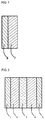
- the inventive power storage device electrode includes a composite material layer 7 and a current collector 6 stacked one on the other.
- the composite material layer 7 is made of a composite material which contains the organic sulfide compound (A) as the electrode active material and the sulfide-containing organic polymer (B) as the binder.
- the current collector 6 include carbon paper, nonwoven carbon fabric, carbon cloth, and metal foils and meshes such as of nickel, aluminum, stainless steel and copper.
- the electrode active material is a material which has electrical conductivity variable due to ion insertion and extraction.
- FIG. 1 the construction of the power storage device electrode is schematically shown, and the thicknesses of the respective layers differ from actual thicknesses.
- the organic sulfide compound (A) to be used for the material for the inventive power storage device electrode functions as the electrode active material.
- the organic sulfide compound (A) preferably has a molecular weight of not greater than 1000, and preferably contains two or more thiol groups or thiolate groups.
- Specific examples of the organic sulfide compound (A) include 2,5-dimercapto-1,3,4-thiadiazole, lithium sulfide, sulfur and 2,4,6-trimereapto-S-triazine, which may be used either alone or in combination.
- the organic sulfide compound (A) is typically used in a proportion of 50 to 98 wt%, preferably 70 to 98 wt%, more preferably 90 to 98 wt%, based on the weight of the overall composite material. If the proportion of the organic sulfide compound (A) is excessively small, it will be impossible to provide a power storage device having a higher energy density. If the proportion of the organic sulfide compound (A) is excessively great, it will be impossible to provide a power storage device having an excellent cycle characteristic.
- the sulfide-containing organic polymer (B) to be used in combination with the organic sulfide compound (A) functions as the binder.
- the sulfide-containing organic polymer (B) include polymers obtained through polymerization in the presence of a thiol chain transfer agent, and polymers obtained through polymerization in the presence of a thiocarbonylthio chain transfer agent.
- the thiol chain transfer agent include 1-dodecanethiol and 1-laurylmercaptothiol.
- Examples of the thiocarbonylthio chain transfer agent include trithiocarbonates, dithiocarbamates and dithiobenzoates.
- acrylonitrile, a (meth)acrylic acid derivative having an oxyethylene group or an oxypropylene group at its side chain, or the like may be further used.
- the sulfide-containing organic polymer (B) include sulfide-containing polyacrylonitrile-methyl acrylate copolymers, and sulfide-containing polyacrylonitrile-(meth)acrylic acid oligoalkylene oxide copolymers such as sulfide-containing polyacrylonitrile-(meth)acrylic acid oligoethylene oxide copolymers and sulfide-containing polyacrylonitrile-(meth)acrylic acid oligopropylene oxide copolymers, which may be used either alone or in combination.
- the sulfide-containing organic polymer (B) is typically used in a proportion of 2 to 50 wt%, preferably 2 to 30 wt%, more preferably 2 to 10 wt%, based on the weight of the overall composite material. If the proportion of the sulfide-containing organic polymer (B) is excessively small, it will be impossible to provide a power storage device having an excellent cycle characteristic. If the proportion of the sulfide-containing organic polymer (B) is excessively great, it will be impossible to provide a power storage device having a higher weight energy density.
- the inventive power storage device electrode may further contain an additional binder, and examples of the additional binder include: polymer materials including chain polymers such as polyethylene glycols and polypropylene glycols and comb-like branched polymers such as polyphosphazenes; and polyvinylidene fluorides, vinylidene fluoride-hexafluoropropylene copolymers, polyacrylonitriles and polymethyl (meth)acrylates. Other examples include poly(meth)acrylates having an oxyethylene group or an oxypropylene group at side chains thereof. These may be used either alone or in combination.
- the material for the inventive power storage device electrode may further contain an electrically conductive agent, which may be an electrically conductive material free from change in its properties due to a potential applied during the discharge of the power storage device.
- an electrically conductive agent include carbon materials and metal materials, among which electrically conductive carbon blacks such as acetylene black and Ketjen black, and fibrous carbon materials such as carbon fibers and carbon nanotubes are preferred.
- electrically conductive carbon blacks are particularly preferred.
- the proportion of the electrically conductive agent in the material for the inventive power storage device electrode is preferably 1 to 30 parts by weight, more preferably 1 to 20 parts by weight, further more preferably 1 to 10 parts by weight, based on 100 parts by weight of the overall electrode active material. Where the proportion of the electrically conductive agent falls within this range, it is possible to effectively improve the weight energy density without impairing the characteristic properties of the inventive power storage device electrode.
- the electrolyte salt and a solvent in which the electrolyte salt is dissolved may be the same as those to be described later for the electrolyte solution.
- the inventive power storage device electrode shown in FIG. 1 is produced, for example, in the following manner. That is, the binder essentially including the sulfide-containing organic polymer (B) is dissolved in a solvent, such as water or an organic solvent, or in an electrolyte solution, and the electrode active material essentially including the organic sulfide compound (A) and, as required, the electrically conductive agent, such as the electrically conductive carbon black, are added to and sufficiently dispersed in the resulting solution, whereby a paste is prepared. The paste is applied onto the current collector 6, and the solvent is evaporated. Thus, the power storage device electrode is produced in a sheet form including the composite material layer 7 stacked on the current collector 6.
- the composite material layer 7 of the inventive power storage device electrode preferably has a thickness of 1 to 1000 ⁇ m, more preferably 10 to 700 ⁇ m.
- the thickness of the electrode is measured, for example, by means of a dial gage (available from Ozaki Mfg. Co. , Ltd.) which is a flat plate including a distal portion having a diameter of 5 mm. The measurement is performed at ten points on a surface of the electrode, and the measurement values are averaged. Then, the thickness of the composite material layer 7 is determined by subtracting the thickness of the current collector 6 from the average thickness of the electrode.
- the composite material layer 7 preferably has a porosity of 20 to 80 %, more preferably 40 to 60 %.
- the porosity is determined from the following expression (1).
- “Apparent volume of composite material layer” is defined as the product obtained by multiplying the area of an electrode surface of the electrode by the thickness of the composite material layer obtained by subtracting the thickness of the current collector from the thickness of the electrode.
- “Actual volume of composite material layer” is defined as the volume of the electrode material excluding the current collector.
- the average density of all the materials for the composite material layer is calculated based on the weight proportions of the respective materials for the composite material layer and the actual densities of the respective materials, and the actual volume of the composite material layer is determined by dividing the total weight of the materials for the composite material layer by the average density.
- PorosInstitut % of composite material layer Apparent volume of composite material layer - Actual volume of composite material layer / Apparent volume of composite material layer ⁇ 100
- Pores formed in the composite material layer 7 preferably have an average pore diameter of 0.1 to 10 ⁇ m, more preferably 0.5 to 5 ⁇ m.
- the diameters of the pores are measured, for example, by a Micromeritics porosimeter AUTOPORE 9520 available from Shimadzu Corporation.
- FIG. 2 illustrates an example of the inventive power storage device, which includes an electrolyte layer 3, and a positive electrode 2 and a negative electrode 4 disposed in opposed relation with the electrolyte layer 3 interposed therebetween.
- reference numerals 1 and 5 designate a positive electrode current collector and a negative electrode current collector, respectively.
- the construction of the power storage device is schematically shown, and the thicknesses of the respective layers differ from the actual thicknesses of the layers.
- the inventive power storage device electrode shown in FIG. 1 may be used as the positive electrode (a stacked component of the positive electrode 2 and the positive electrode current collector 1) or as the negative electrode (a stacked component of the negative electrode 4 and the negative electrode current collector 5). Particularly, where the inventive power storage device electrode shown in FIG. 1 is used as the positive electrode and an electrode containing at least one selected from compounds and metals capable of ion insertion/extraction is used as the negative electrode, the resulting power storage device has a higher energy density.
- Carbon paper, nonwoven carbon fabric, carbon cloth, or a metal foil or a mesh such as of nickel, aluminum, stainless steel or copper may be used as the positive electrode current collector 1 and the negative electrode current collector 5 shown in FIG. 2 .
- the electrolyte layer 3 of the inventive power storage device is formed from an electrolyte.
- a sheet including a separator impregnated with an electrolyte solution or a sheet made of a solid electrolyte is preferably used.
- the sheet made of the solid electrolyte per se doubles as a separator.
- the inventive power storage device electrode is less liable to suffer from the dissolution of the electrode active material in the electrolyte solution due to repeated charge/discharge. Therefore, the electrolyte layer 3 is not limited to the solid electrolyte sheet and the electrolyte solution impregnated sheet, but the electrolyte solution may be used as it is for the electrolyte layer 3.
- the electrolyte solution is used as it is or where the separator and the electrodes are impregnated with the electrolyte solution
- preferred examples of the electrolyte for the electrolyte solution include compounds including a metal ion such as a lithium ion in combination with a proper counter ion such as a sulfonate ion, a perchlorate ion, a tetrafluoroborate ion, a hexafluorophosphate ion, a hexafluoroarsenic ion, a bis(trifluoromethanesulfonyl)imide ion, a bis(pentafluoroethanesulfonyl)imide ion or a halide ion.
- a metal ion such as a lithium ion in combination with a proper counter ion such as a sulfonate ion, a perchlorate ion,
- electrolyte examples include LiCF 3 SO 3 , LiClO 4 , LiBF 4 , LiPF 6 , LiAsF 6 , LiN(SO 2 CF 3 ) 2 . LiN(SO 2 C 2 F 5 ) 2 and LiCl.
- the solvent for the electrolyte solution examples include nonaqueous solvents, i.e., organic solvents, such as carbonates, nitriles, amides and ethers at least one of which is used.
- organic solvents include ethylene carbonate, propylene carbonate, butylene carbonate, dimethyl carbonate, diethyl carbonate, ethyl methyl carbonate, acetonitrile, propionitrile, N,N'-dimethylacetamide, N-methyl-2-pyrrolidone, dimethoxyethane, diethoxyethane and ⁇ -butyrolactone.
- electrolyte solution impregnated separator is used as the electrolyte layer 3, as described above, any of the aforementioned electrolytes for the electrolyte solution may be used.
- Examples of the solvent for the electrolyte solution include water, and organic solvents such as carbonates, alcohols, nitriles, amides and ethers at least one of which is used.
- the separator may be an insulative porous sheet, which is capable of preventing electrical short circuit between the positive electrode and the negative electrode disposed in opposed relation with the intervention of the separator and has electrochemical stability, higher ion permeability and a certain mechanical strength. Therefore, exemplary materials for the separator include paper, nonwoven fabrics and porous resin sheets such as of polypropylenes, polyethylenes and polyimides, which may be used either alone or in combination.
- the electrode containing at least one selected from the compounds and the metals capable of ion insertion/extraction is used as the negative electrode, as described above, preferred examples of the compounds and the metals include metal lithium, carbon materials and transition metal oxides capable of insertion and extraction of lithium ions in oxidation and reduction, silicon and tin.
- the term "use” means that the specific material is used alone, as well as that the specific material is used in combination with other material. The proportion of the other material is less than 50 wt% based on the total weight of the materials.
- the inventive power storage device may be provided in a variety of forms including a laminate cell form, a porous sheet form, a sheet form, a square form, a cylindrical form and a button form.
- the power storage device is preferably assembled in a glove box in an inert gas atmosphere such as an ultrapure argon gas atmosphere.
- Polymers were prepared by the following exemplary production processes 1 and 2 before the production of power storage devices according to the inventive examples and the comparative example.
- the resulting solution was concentrated by means of a rotary evaporator, and the concentrated solution was poured in 900 ml of ethanol for re-precipitation. Then, the resulting precipitate was separated through decantation, and dissolved in 100 ml of dimethyl sulfoxide. This operation was repeated twice, and then the resulting precipitate was re-precipitated in 900 ml of methanol. The resulting precipitate was washed with methanol, and filtered out. The resulting solid component was dried through a heat and vacuum drying process over night by means of a vacuum dryer kept at 40°C (with a yield amount of 14.6 g and a yield percentage of 20.6 %).
- a tetrafluoroboric acid aqueous solution (special grade reagent available from Wako Pure Chemical Industries, Ltd.) having a concentration of 42 wt% was added to 138 g of ion-exchanged water contained in a 300-mL volume glass beaker. Then, 10.0 g (0.107 mol) of aniline was added to the resulting solution, while the solution was stirred by a magnetic stirrer.
- aniline was dispersed in an oily droplet form in the tetrafluoroboric acid aqueous solution, and then dissolved in water in several minutes to provide a homogeneous transparent aniline aqueous solution.
- the aniline aqueous solution thus prepared was cooled to -4°C or lower with the use of a refrigerant bath.
- the electrically conductive polyaniline powder was milled in an agate mortar, the resulting powder was compacted into an electrically conductive polyaniline disk having a thickness of 720 ⁇ m at a pressure of 300 MPa in vacuum for 10 minutes by means of a KBr tablet forming device for infrared spectrum measurement.
- the disk had an electrical conductivity of 19.5 S/cm as measured by Van der Pauw's four-point electrical conductivity measurement method.
- the electrically conductive polyaniline powder prepared in the doped state in the aforementioned manner was put in a 2 mol/dm 3 sodium hydroxide aqueous solution, and the resulting mixture was stirred for 30 minutes, whereby the electrically conductive polyaniline was neutralized.
- the polyaniline was dedoped with the tetrafluoroboric acid dopant removed therefrom.
- the dedoped polyaniline was washed with water until the filtrate became neutral. Then, the dedoped polyaniline was washed in acetone with stirring, and suction-filtered through No. 2 filter paper with the use of a Buchner funnel and a suction bottle. Thus, dedoped polyaniline powder was provided on the No.2 filter paper. The resulting powder was dried in vacuum at a room temperature for 10 hours, whereby brown dedoped polyaniline powder was provided.
- the dedoped polyaniline powder was put in a methanol aqueous solution of phenylhydrazine, and reduced for 30 minutes with stirring.
- the color of the polyaniline powder turned from brown to gray.
- the resulting polyaniline powder was washed with methanol and then with acetone, filtered, and dried in vacuum at a room temperature.
- reduced dedoped polyaniline reduced polyaniline
- the resulting powder had a median diameter of 13 ⁇ m as measured by a light scattering method with the use of acetone as a solvent.
- the resulting powder was compacted into a reduced dedoped polyaniline disk having a thickness of 720 ⁇ m at a pressure of 75 MPa in vacuum for 10 minutes by means of a KBr tablet forming device for infrared spectrum measurement.
- the disk had an electrical conductivity of 5.8 ⁇ 10 -3 S/cm as measured by Van der Pauw's four-point electrical conductivity measurement method.
- the polyaniline had a higher electrical conductivity in an ion-inserted oxidized state than in an ion-extracted reduced state. Therefore, the polyaniline was an electrode active material having an electrical conductivity variable due to the ion insertion/extraction.
- An electrolyte solution was prepared which contained 4.6 g of lithium tetrafluoroborate, 20.9 g of propylene carbonate and 15.7 g of ethylene carbonate. Then, 1 g of the sulfide-containing polyacrylonitrile-methyl acrylate copolymer prepared in Exemplary Production Process 1 was dissolved in 6.88 g of the electrolyte solution at 140°C.
- an electrode sheet which included a current collector of the carbon paper and a composite material layer formed from the slurry on the carbon paper.
- the weight of the active material in the electrode sheet was 3.32 mg/cm 2 .
- the weight was determined by multiplying the weight of the composite material layer (obtained by subtracting the weight of the carbon paper from the weight of the electrode sheet) by the weight fraction of the polyaniline and the DMcT with respect to the total weight of the solid components of the lithium tetrafluoroborate, the polyaniline, the DMcT, the electrically conductive carbon black and the sulfide-containing polyacrylonitrile-methyl acrylate copolymer.
- the thickness of the electrode was measured by means of a dial gage (available from Ozaki Mfg. Co., Ltd.) which was a flat plate including a distal portion having a diameter of 5 mm. The measurement was performed at ten points on a surface of the sheet, and the measurement values were averaged. Then, the thickness of the composite material layer was determined by subtracting the thickness of the carbon paper from the average thickness. As a result, the thickness of the composite material layer was 42 ⁇ m.
- the porosity of the composite material layer was 40 % as determined from the above expression (1).
- the pores of the composite material layer had an average pore diameter of 3.5 ⁇ m as measured by means of a Micromeritics porosimeter AUTOPORE 9520 available from Shimadzu Corporation.
- a power storage device (cell) employing the above electrode sheet as its positive electrode was assembled in the following manner.
- the electrode sheet was prepared as the positive electrode.
- coin-shaped metal lithium available from Honjo Metal Co., Ltd.
- TF40-50 available from Hohsen Corporation
- An acrylonitrile-methyl acrylate copolymer was prepared in substantially the same manner as in Exemplary Production Process 1, except that 1-dodecanethiol was not blended.
- an electrolyte solution was prepared by dissolving 1 g of the copolymer in a solution containing 0.77 g of lithium tetrafluoroborate, 3.49 g of propylene carbonate and 3.62 g of ethylene carbonate.
- a battery assembling process was performed in an ultrapure argon gas atmosphere in a glove box (having a dew point of -100°C).
- the positive electrode and the negative electrode were placed in properly opposed relation in a stainless steel HS cell (available from Hohsen Corporation) adapted for an experiment of a nonaqueous electrolyte secondary battery, and the separator was properly positioned so as to prevent short circuit between the positive electrode and the negative electrode.
- the electrolyte solution was injected into the cell. Thereafter, a solution injection port was heat-sealed, whereby the HS cell was sealed. Thus, the cell was completed.
- the active material in the cell had a weight capacity density of 147 mAh/g
- the total capacity (mAh) was calculated based on the weight of the active material contained in a unit electrode area.
- a rate at which the total capacity thus calculated was charged in 1 hour was defined as 1C charge/discharge rate.
- the weight capacity density and the weight energy density of the cell were 330 mAh/g and 975 mWh/g, respectively, as measured when the charge/discharge process was performed at 0.05C charge/discharge rate once.
- the weight capacity density and the energy density of the cell were measured in the following manner.
- the cell was allowed to stand still in a constant-temperature chamber at 25°C, and measurement was performed in a constant current and constant voltage charge/constant current discharge mode by means of a battery charge/discharge device (SD8 available from Hokuto Denko Corporation).
- the charge termination voltage was set to 3.8 V. After the voltage reached 3.8 V through a constant current charge process, a constant voltage charge process was further performed at 3.8 V until the current value reached 20 % of the current value observed in the constant current charge process. A capacity observed at this time was defined as a charge capacity. Thereafter, a constant current discharge process was performed to a discharge termination voltage of 2.0 V. A weight capacity density was measured in the fifth cycle. The weight capacity density was based on a net weight of the positive electrode active material.
- the energy density of the cell was measured in a constant current and constant voltage charge/constant current discharge mode at 25°C by means of a battery charge/discharge device (SD8 available from Hokuto Denko Corporation).
- the charge termination voltage was set to 3.8 V. After the voltage reached 3.8 V through a constant current charge process, a constant voltage charge process was further performed at 3.8 V for 2 minutes. Thereafter, a constant current discharge process was performed to a discharge termination voltage of 2.0 V, and the weight energy density was measured.
- the active material had a weight capacity density of 150 mAh/g
- the full capacity density (mAh/g) was calculated based on the weight of the active material contained in a unit electrode area of the cell. The weight energy density was determined so that the cell was charged to the full capacity and discharged in 20 hours (0.05 C).
- An electrode sheet (positive electrode) was produced in substantially the same manner as in Example 1, except that N-methyl-2-pyrrolidone was used instead of acetonitrile.
- the weight of the active material in the electrode sheet was 1.51 mg/cm 2 as measured in the same manner as in Example 1.
- the composite material layer of the electrode sheet had a thickness of 35 ⁇ m, a porosity of 32 % and an average pore diameter of 2.5 ⁇ m as measured in the same manner as in Example 1.
- a cell power storage device was produced in substantially the same manner as in Example 1, except that the electrode sheet produced in the aforementioned manner was used as the positive electrode.
- the cell had a capacity density of 320 mAh/g and an energy density of 850 mWh/g as measured in the same manner as in Example 1.
- An electrode sheet (positive electrode) was produced in substantially the same manner as in Example 1, except that the polyaniline (produced in Exemplary Production Process 2) was not blended and the proportion of the electrically conductive carbon black (DENKA BLACK available from Denki Kagaku Kogyo K.K.) was 0.067 g.
- the weight of the active material in the electrode sheet was 1.23 mg/cm 2 as measured in the same manner as in Example 1.
- the composite material layer of the electrode sheet had a thickness of 41 ⁇ m, a porosity of 37 % and an average pore diameter of 2.3 ⁇ m as measured in the same manner as in Example 1.
- a cell power storage device was produced in substantially the same manner as in Example 1, except that the electrode sheet produced in the aforementioned manner was used as the positive electrode.
- the cell had a capacity density of 310 mAh/g and an energy density of 780 mWh/g as measured in the same manner as in Example 1.
- An electrode sheet (positive electrode) was produced in substantially the same manner as in Example 1, except that a polyacrylonitrile-methyl acrylate copolymer synthesized without the addition of 1-dodecanethiol in Exemplary Production Process 1 was used instead of the sulfide-containing polyacrylonitrile-methyl acrylate copolymer.
- the weight of the active material in the electrode sheet was 2.72 mg/cm 2 as measured in the same manner as in Example 1.
- the composite material layer of the electrode sheet had a thickness of 40 ⁇ m, a porosity of 42 % and an average pore diameter of 3.0 ⁇ m as measured in the same manner as in Example 1.
- a cell power storage device was produced in substantially the same manner as in Example 1, except that the electrode sheet produced in the aforementioned manner was used as the positive electrode.
- the cell had a capacity density of 220 mAh/g and an energy density of 660 mWh/g as measured in the same manner as in Example 1.
- the power storage device employing the inventive power storage device electrode can be advantageously used as a lithium secondary battery and other power storage device, and a higher-capacity capacitor.
- the inventive power storage device can be used for the same applications as the prior art secondary batteries and electrical double-layer capacitors, for example, for mobile electronic apparatuses such as mobile PCs, mobile phones and personal digital assistants (PDAs), and for drive power sources for hybrid electric cars, electric cars and fuel battery cars.
- mobile electronic apparatuses such as mobile PCs, mobile phones and personal digital assistants (PDAs)
- PDAs personal digital assistants
Landscapes
- Chemical & Material Sciences (AREA)
- Chemical Kinetics & Catalysis (AREA)
- Electrochemistry (AREA)
- General Chemical & Material Sciences (AREA)
- Engineering & Computer Science (AREA)
- Materials Engineering (AREA)
- Power Engineering (AREA)
- Composite Materials (AREA)
- Manufacturing & Machinery (AREA)
- Microelectronics & Electronic Packaging (AREA)
- Battery Electrode And Active Subsutance (AREA)
- Secondary Cells (AREA)
- Electric Double-Layer Capacitors Or The Like (AREA)
Applications Claiming Priority (2)
| Application Number | Priority Date | Filing Date | Title |
|---|---|---|---|
| JP2013064456A JP2014191915A (ja) | 2013-03-26 | 2013-03-26 | 蓄電デバイス用電極およびそれを用いた蓄電デバイス |
| PCT/JP2014/058024 WO2014157059A1 (fr) | 2013-03-26 | 2014-03-24 | Électrode pour dispositif de stockage d'électricité et dispositif de stockage d'électricité utilisant ladite électrode |
Publications (1)
| Publication Number | Publication Date |
|---|---|
| EP2980896A1 true EP2980896A1 (fr) | 2016-02-03 |
Family
ID=51624033
Family Applications (1)
| Application Number | Title | Priority Date | Filing Date |
|---|---|---|---|
| EP14772631.9A Withdrawn EP2980896A1 (fr) | 2013-03-26 | 2014-03-24 | Électrode pour dispositif de stockage d'électricité et dispositif de stockage d'électricité utilisant ladite électrode |
Country Status (5)
| Country | Link |
|---|---|
| US (1) | US20160043400A1 (fr) |
| EP (1) | EP2980896A1 (fr) |
| JP (1) | JP2014191915A (fr) |
| CN (1) | CN105051956A (fr) |
| WO (1) | WO2014157059A1 (fr) |
Families Citing this family (5)
| Publication number | Priority date | Publication date | Assignee | Title |
|---|---|---|---|---|
| US20230312496A1 (en) * | 2020-08-26 | 2023-10-05 | The Lubrizol Corporation | 2,5-Dimercapto-1,3,4-Thiadiazole (DMTD) Metal Salt Derivatives |
| JP7674122B2 (ja) * | 2021-03-23 | 2025-05-09 | Tdk株式会社 | リチウムイオン二次電池用正極及びリチウムイオン二次電池 |
| CN113594545B (zh) * | 2021-07-27 | 2022-12-02 | 宁德新能源科技有限公司 | 锂硫电池及包含该锂硫电池的电子装置 |
| JP2023038096A (ja) * | 2021-09-06 | 2023-03-16 | ソフトバンク株式会社 | 二次電池用電極、二次電池、飛行体、及び、二次電池用電極の生産方法 |
| FR3143203B1 (fr) * | 2022-12-07 | 2025-12-26 | Renault Sas | Electrode et électrolyte pour batterie lithium-ion incorporant un composé polymère |
Family Cites Families (12)
| Publication number | Priority date | Publication date | Assignee | Title |
|---|---|---|---|---|
| US4963161A (en) * | 1989-07-10 | 1990-10-16 | At&T Bell Laboratories | Non-aqueous alkali battery having an improved cathode |
| JP2715778B2 (ja) * | 1991-01-29 | 1998-02-18 | 松下電器産業株式会社 | 可逆性電極材料 |
| JP2940198B2 (ja) | 1991-03-27 | 1999-08-25 | 松下電器産業株式会社 | 固形電極組成物 |
| JPH06163049A (ja) * | 1992-11-17 | 1994-06-10 | Matsushita Electric Ind Co Ltd | 電 極 |
| JPH06283175A (ja) * | 1993-03-26 | 1994-10-07 | Matsushita Electric Ind Co Ltd | 可逆性電極 |
| JP3292441B2 (ja) | 1996-03-21 | 2002-06-17 | 松下電器産業株式会社 | 有機ジスルフィド化合物を含有する電極およびその製造方法 |
| JPH11228902A (ja) * | 1998-02-17 | 1999-08-24 | Elf Atochem Japan Kk | フッ化ビニリデン系樹脂の金属基材への接着方法、電極構造体、およびその作製方法 |
| CN100427527C (zh) * | 2006-06-08 | 2008-10-22 | 上海交通大学 | 有机硫聚合物在二次镁电池正极材料中的应用 |
| WO2009145225A1 (fr) * | 2008-05-29 | 2009-12-03 | Dic株式会社 | Batterie secondaire, son procédé de fabrication, et encre de formation d'électrode |
| CN101630758A (zh) * | 2008-07-16 | 2010-01-20 | 比亚迪股份有限公司 | 一种锂离子二次电池及其制备方法 |
| US8603681B2 (en) * | 2009-07-01 | 2013-12-10 | Basf Se | Porous film material comprising at least one carbonaceous semimetal oxide phase, and use thereof as a separator material for electrochemical cells |
| CN102983361B (zh) * | 2012-11-23 | 2015-04-22 | 中国人民解放军国防科学技术大学 | 用于Li-S电池的电解液及其制备方法和包含该电解液的Li-S电池 |
-
2013
- 2013-03-26 JP JP2013064456A patent/JP2014191915A/ja active Pending
-
2014
- 2014-03-24 US US14/779,030 patent/US20160043400A1/en not_active Abandoned
- 2014-03-24 WO PCT/JP2014/058024 patent/WO2014157059A1/fr not_active Ceased
- 2014-03-24 CN CN201480018062.3A patent/CN105051956A/zh active Pending
- 2014-03-24 EP EP14772631.9A patent/EP2980896A1/fr not_active Withdrawn
Also Published As
| Publication number | Publication date |
|---|---|
| CN105051956A (zh) | 2015-11-11 |
| US20160043400A1 (en) | 2016-02-11 |
| WO2014157059A1 (fr) | 2014-10-02 |
| JP2014191915A (ja) | 2014-10-06 |
Similar Documents
| Publication | Publication Date | Title |
|---|---|---|
| Du Pasquier et al. | Li4Ti5O12/poly (methyl) thiophene asymmetric hybrid electrochemical device | |
| US8617744B2 (en) | Electricity storage device | |
| JP5146049B2 (ja) | 蓄電デバイス | |
| EP2913879B1 (fr) | Batterie secondaire à électrolyte non aqueux et procédé de fabrication de celle-ci | |
| JP7107491B2 (ja) | 電池用非水電解液及びリチウム二次電池 | |
| US20160141621A1 (en) | Power storage device electrode, method of manufacturing same, and power storage device including same | |
| KR20190032390A (ko) | 축전 디바이스용 양극 및 축전 디바이스 | |
| KR20090080909A (ko) | 전지 | |
| US20210218060A1 (en) | Electrolyte composition and use thereof in lithium-ion batteries | |
| EP2980896A1 (fr) | Électrode pour dispositif de stockage d'électricité et dispositif de stockage d'électricité utilisant ladite électrode | |
| US20210193399A1 (en) | Positive electrode for power storage device and power storage device | |
| JP2011077051A (ja) | 負極活物質、負極および電池 | |
| JP2015165481A (ja) | 電極およびそれを用いた蓄電デバイス | |
| JP3434677B2 (ja) | 非水溶媒電解液を有する二次電池 | |
| JP2004158286A (ja) | ポリ(3,4−エチレンジオキシチオフェン)を含有する正極材料複合体および該複合体からなる正極を有するリチウム二次電池 | |
| CN100536199C (zh) | 阳极活性材料和电池 | |
| CN104854753A (zh) | 非水电解液二次电池及其使用的正极 | |
| JP5082221B2 (ja) | 二次電池用負極および二次電池 | |
| WO2014024941A1 (fr) | Électrode positive pour dispositif de charge ainsi que procédé de fabrication de celle-ci, matière active d'électrode positive pour dispositif de charge ainsi que procédé de fabrication de celle-ci, et dispositif de charge | |
| JP2014197511A (ja) | 非水電解液二次電池 | |
| WO2014103780A1 (fr) | Accumulateur à électrolyte non aqueux et feuille d'électrode positive utilisée dans l'accumulateur | |
| JP2015165479A (ja) | 有機活物質およびそれを用いた蓄電デバイス | |
| WO2019208733A1 (fr) | Électrode positive pour dispositif de stockage d'énergie et dispositif de stockage d'énergie | |
| JP2007179955A (ja) | 負極およびそれを用いた電池 | |
| JP2015011876A (ja) | 電極の製法、それにより得られた電極およびそれを用いた蓄電デバイス |
Legal Events
| Date | Code | Title | Description |
|---|---|---|---|
| PUAI | Public reference made under article 153(3) epc to a published international application that has entered the european phase |
Free format text: ORIGINAL CODE: 0009012 |
|
| 17P | Request for examination filed |
Effective date: 20150923 |
|
| AK | Designated contracting states |
Kind code of ref document: A1 Designated state(s): AL AT BE BG CH CY CZ DE DK EE ES FI FR GB GR HR HU IE IS IT LI LT LU LV MC MK MT NL NO PL PT RO RS SE SI SK SM TR |
|
| AX | Request for extension of the european patent |
Extension state: BA ME |
|
| STAA | Information on the status of an ep patent application or granted ep patent |
Free format text: STATUS: THE APPLICATION HAS BEEN WITHDRAWN |
|
| 18W | Application withdrawn |
Effective date: 20160217 |