EP2980923B1 - Bloc d'automatisation pour l'automatisation industrielle de processus - Google Patents
Bloc d'automatisation pour l'automatisation industrielle de processus Download PDFInfo
- Publication number
- EP2980923B1 EP2980923B1 EP14179093.1A EP14179093A EP2980923B1 EP 2980923 B1 EP2980923 B1 EP 2980923B1 EP 14179093 A EP14179093 A EP 14179093A EP 2980923 B1 EP2980923 B1 EP 2980923B1
- Authority
- EP
- European Patent Office
- Prior art keywords
- automation
- attachment means
- assembly
- housing
- shielding sheet
- Prior art date
- Legal status (The legal status is an assumption and is not a legal conclusion. Google has not performed a legal analysis and makes no representation as to the accuracy of the status listed.)
- Not-in-force
Links
Images


Classifications
-
- H—ELECTRICITY
- H05—ELECTRIC TECHNIQUES NOT OTHERWISE PROVIDED FOR
- H05K—PRINTED CIRCUITS; CASINGS OR CONSTRUCTIONAL DETAILS OF ELECTRIC APPARATUS; MANUFACTURE OF ASSEMBLAGES OF ELECTRICAL COMPONENTS
- H05K7/00—Constructional details common to different types of electric apparatus
- H05K7/14—Mounting supporting structure in casing or on frame or rack
- H05K7/1462—Mounting supporting structure in casing or on frame or rack for programmable logic controllers [PLC] for automation or industrial process control
- H05K7/1468—Mechanical features of input/output (I/O) modules
- H05K7/1472—Bus coupling modules, e.g. bus distribution modules
-
- H—ELECTRICITY
- H01—ELECTRIC ELEMENTS
- H01R—ELECTRICALLY-CONDUCTIVE CONNECTIONS; STRUCTURAL ASSOCIATIONS OF A PLURALITY OF MUTUALLY-INSULATED ELECTRICAL CONNECTING ELEMENTS; COUPLING DEVICES; CURRENT COLLECTORS
- H01R13/00—Details of coupling devices of the kinds covered by groups H01R12/70 or H01R24/00 - H01R33/00
- H01R13/648—Protective earth or shield arrangements on coupling devices, e.g. anti-static shielding
- H01R13/658—High frequency shielding arrangements, e.g. against EMI [Electro-Magnetic Interference] or EMP [Electro-Magnetic Pulse]
- H01R13/6591—Specific features or arrangements of connection of shield to conductive members
- H01R13/6596—Specific features or arrangements of connection of shield to conductive members the conductive member being a metal grounding panel
-
- H—ELECTRICITY
- H01—ELECTRIC ELEMENTS
- H01R—ELECTRICALLY-CONDUCTIVE CONNECTIONS; STRUCTURAL ASSOCIATIONS OF A PLURALITY OF MUTUALLY-INSULATED ELECTRICAL CONNECTING ELEMENTS; COUPLING DEVICES; CURRENT COLLECTORS
- H01R13/00—Details of coupling devices of the kinds covered by groups H01R12/70 or H01R24/00 - H01R33/00
- H01R13/46—Bases; Cases
- H01R13/502—Bases; Cases composed of different pieces
- H01R13/504—Bases; Cases composed of different pieces different pieces being moulded, cemented, welded, e.g. ultrasonic welding, or swaged together
-
- H—ELECTRICITY
- H01—ELECTRIC ELEMENTS
- H01R—ELECTRICALLY-CONDUCTIVE CONNECTIONS; STRUCTURAL ASSOCIATIONS OF A PLURALITY OF MUTUALLY-INSULATED ELECTRICAL CONNECTING ELEMENTS; COUPLING DEVICES; CURRENT COLLECTORS
- H01R25/00—Coupling parts adapted for simultaneous co-operation with two or more identical counterparts, e.g. for distributing energy to two or more circuits
- H01R25/006—Coupling parts adapted for simultaneous co-operation with two or more identical counterparts, e.g. for distributing energy to two or more circuits the coupling part being secured to apparatus or structure, e.g. duplex wall receptacle
-
- H—ELECTRICITY
- H01—ELECTRIC ELEMENTS
- H01R—ELECTRICALLY-CONDUCTIVE CONNECTIONS; STRUCTURAL ASSOCIATIONS OF A PLURALITY OF MUTUALLY-INSULATED ELECTRICAL CONNECTING ELEMENTS; COUPLING DEVICES; CURRENT COLLECTORS
- H01R31/00—Coupling parts supported only by co-operation with counterpart
- H01R31/005—Intermediate parts for distributing signals
Definitions
- the invention is based on an automation assembly for industrial process automation, comprising a housing with a first integrated fastener and a second integrated fastener, which are arranged opposite, a first data terminal, a second data terminal, an electronic circuit board, wherein the first data terminal and the second Data connection are arranged in the region of the first fastening means.
- shielded data lines For data communication with automation modules, it is necessary to use shielded data lines, especially in the heavy industrial EMC environment. These data lines are connected, for example via circular connectors with the automation modules. In order to ensure shield connection from the cable of the data line via the circular connector to a printed circuit board of the automation module, metal housings for the automation module are used in the prior art.
- the object is achieved in that the first fastening means is a combination of a molding of the housing and a Integration of an electrically conductive shielding plate, wherein the housing is designed as an injection molded part and the shield plate as a stamped and bent part is coated and the stamped bent part such that a shield plate having surface for a ground connection of the data terminals and the circuit board is directed to the outside of the housing, in that an electrically conductive counter-fastening means guided by a recess arranged in the first fastening means makes electrical contact with the surface, wherein the shielding sheet has a first annular opening and a second annular opening, into the first annular opening for the first data connection an electrically conductive first cylindrical one Fastening insert and in the second annular opening for the second data terminal, an electrically conductive second cylindrical fastening insert is pressed such that an electrical contact between the ringf örmigen openings and the attachment inserts is formed.
- the counter-fastening means may for example be a metallic screw, which is pushed through the hole of the first fastener, the head of the metallic screw thus rests on the surface and in turn makes electrical contact with the surface, the metallic screw, for example with a nut screwed in a control cabinet or on a metallic mounting rail.
- a metallic screw which is pushed through the hole of the first fastener, the head of the metallic screw thus rests on the surface and in turn makes electrical contact with the surface, the metallic screw, for example with a nut screwed in a control cabinet or on a metallic mounting rail.
- Through the screw connection ensures that the module with its shroud a good ground connection with a functional earth, as provided for example in a control cabinet or a mounting rail reached.
- the housing must not be made completely made of metal, but is manufactured in a plastic injection molding process, the sensitive point is surrounded in the data ports with a shield plate and the shield during The injection molding process is overmoulded.
- the housing has already been produced by the plastic injection molding process, while the shielding plate was injected into the housing with.
- the housing has corresponding holes. These holes are used in a production of the automation module the cylindrical attachment inserts are pressed into the annular openings.
- the shield plate with its annular openings and the electrical contact from the annular openings to the mounting inserts now forms a closed EMC shield for the data connections, for the data connections.
- the cylinders have corrugations at a first end and a collar at their second ends.
- the corrugation sits after a press-fit in the annular openings within the ring of the annular openings.
- the collar is preferably later on a housing surface of the molded plastic housing.
- the cylinder in automation assemblies, which must have an increased resistance to moisture, such as IP 67 or impermeability to temporary submersion, it is advantageous if the cylinder have on their lateral surface a circumferential sealing lip.
- the circumferential sealing lip forms a tight connection with the plastic molded housing.
- the shield plate is configured as a U-shaped main part with a first leg, a second leg and a middle part, the first leg and the second leg each have a punched hole, which are arranged congruently opposite to perform the fastening means to Attach the assembly in a side position.
- the central part has a further punching hole for passing the counter-fastening means for fixing in a supine position of the assembly, which corresponds to a position rotated by 90 degrees to the lateral position.
- a further refined embodiment of the shielding plate is configured such that at least one connecting web to the first annular opening and the second annular opening is arranged on the U-shaped main part.
- the cylindrical attachment inserts are designed as a metal threaded insert for screw-type circular connector.
- the cylindrical mounting inserts with the shroud are designed as a closed EMC shield in the data ports area, and at the same time the EMC shield is reinforced or the EMC shield forms the fastener.
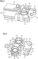
- the automation module 1 comprises a housing 2 with a first integrated fastening means 11 and a second integrated fastening means 12, which are arranged opposite one another.
- the automation module 1 has a first data connection 21 and a second data connection 22.
- the automation module has further inputs for process signals, which are arranged via an electronic circuit board 30 arranged inside the automation module 1 (see FIG FIG. 2 ) are evaluated and processed.
- the first data connection 21 and the second data connection 22 are arranged in the region of the first fastening means 11.
- the first fastening means 11 as a combination of a molding of the housing 2 and an integration of an electrically conductive shielding plate 31 (see FIGS. 2 to 4 ) designed.
- the housing 2 is designed as an injection molded part and the shield plate 31 as a stamped and bent part.
- the stamped and bent part is encapsulated in such a way that a face 32 having the shield plate 31 for ground connection of the data connections 21, 22 and the printed circuit board 30 is directed towards the outside of the housing 2 in such a way that a recess arranged in the first fastening means 11, wherein the recess may be a first recess 41, a second recess 42 or a third recess 43, guided electrically conductive counter-fastening means with the surface 32 makes electrical contact.
- FIG. 2 is that out FIG. 1 known automation assembly in an open view with a raised housing 2 shown.
- the shroud 31 has a first annular opening 51 and a second annular opening 52, into the first annular opening 51 is an electrically conductive first cylindrical attachment insert 61 for the first data port 21 and into the second annular port 51 for the second data port 22 a electrically conductive second cylindrical fastening insert 62 is pressed in such a way that an electrical contact between the annular openings 51,52 and the fastening inserts 61,62 arises.
- the shroud 31 is electrically connected to both the cylindrical attachment inserts 61, 62 and the circuit board 30.
- a third connecting web 83 leads from the shield plate 31 to the printed circuit board 30, wherein an eyelet of the third connecting web 83 is screwed to the printed circuit board 30 by a screw connection.
- the shield plate 31 contacts via the third connecting web 83 a ground layer of the printed circuit board 30. This ground contact is passed through the printed circuit board 30 to a second printed circuit board 30a via a concealed connector.
- the automation module 1 has a cover 3 and a seal 4.
- FIG. 3 shows the shield plate 31 and the cylindrical attachment inserts 61,62 in a detailed view.
- the cylindrical attachment inserts 61,62 form with the shroud 31 in the data ports 21,22 a closed EMC shield and at the same time forms this closed EMC shield as a combination of shroud 31 as stamped and cylindrical attachment inserts 61,62 a reinforcement for the first Fastening means 11.
- the shield plate 31 forms by the surface 32 an electrical contact surface, which is not coated in the mentioned injection molding process with plastic.
- This surface 32 is used as a contact surface for, for example, a screw.
- the screw is formed by a punching hole formed in the shroud 31, for example, a first punch hole 71, a second punch hole 72, or a third punch hole 73 (see FIG FIG. 4 ) through.
- the head of the screw makes electrical contact with the shroud 31, and thus can provide a functional ground connection by mounting the automation assembly, for example, to the metallic enclosure of a machine.
- FIG. 4 shows in detail the shield plate 31 with the pressed-cylindrical cylindrical fastening inserts 61, 62nd
- the shield plate 31 is configured as a U-shaped main part 33 with a first leg 34 and a second leg 35 and a middle part 36.
- the first leg 34 and the second leg 35 each have a punched hole 71, 72, which are arranged congruently opposite one another for the passage of the counter-fastening means and serve to fasten the assembly in a lateral position.
- a further third punched hole 73 for carrying out the counter-fastening means is arranged in the middle part 36. If the automation module 1 by plugging fastened to the counter-fastening means by the third punch hole, the automation assembly 1 is mounted in a supine position, which corresponds to a position rotated by 90 degrees to the side position.
- a first connecting web 81 and a second connecting web 82 is arranged on the U-shaped main part 33.
- the connecting webs 81, 82 connect the middle part 36 of the shielding plate 31 respectively to the first annular opening 51 and the second annular opening 52.
- the electrically conductive first cylindrical fastening insert 61 is pressed into the first annular opening 51 for the first data connection 21 and into the second Opening 52 is pressed for the second data terminal 22 of the electrically conductive second cylindrical attachment insert 62.
- the injection is carried out by the already finished sprayed housing, wherein the shroud 31 was molded in the finished sprayed housing and is an integral part of the housing.
- the cylindrical fastening inserts 61, 62 are pressed into the annular openings 51, 52 in such a way that an electrical contact is produced between the annular openings 51, 52 and the fastening inserts 61, 62.
- the cylinders In order to improve the electrical contact and the press-fitting process, the cylinders have a corrugation 60 at their first end 61a and a collar 63 at their second end 61b.
- the annular openings 51,52 are further connected via a third connecting web 83 to a ground layer of the printed circuit board 30 (see FIG. 3 ) connectable. This results in a closed EMC shield in the region of the data ports 21,22 through the cylindrical mounting inserts 61,62 in combination with the shield plate 31 and at the same time the shield plate 31 forms a reinforced attachment means eleventh
Landscapes
- Engineering & Computer Science (AREA)
- Automation & Control Theory (AREA)
- Microelectronics & Electronic Packaging (AREA)
- Shielding Devices Or Components To Electric Or Magnetic Fields (AREA)
- Details Of Connecting Devices For Male And Female Coupling (AREA)
Claims (9)
- Bloc (1) d'automatisation pour l'automatisation de processus industriel, comprenant
un boîtier (2) ayant un premier moyen (11) de fixation intégré,
une première borne (21) de données,
une deuxième borne (22) de données,
une plaquette (30) électronique à circuit imprimé,
dans lequel la première borne (21) de données et la deuxième borne (22) de données sont disposées dans la région du premier moyen (11) de fixation,
caractérisé en ce que
le boîtier a un deuxième moyen (12) de fixation intégré, qui est disposé à l'opposé du premier moyen (11) de fixation et en ce que
le premier moyen (11) de fixation est une combinaison d'une déformation du boîtier (2) et d'une intégration d'une tôle (31) formant écran conductrice de l'électricité, le boîtier (2) étant sous la forme d'une pièce moulée par injection et la tôle (31) formant écran sous la forme d'une pièce estampée pliée et la pièce estampée pliée étant recouverte par extrusion, en ce qu'une surface (32), ayant la tôle (31) formant écran, est, pour une liaison à la masse des bornes (21, 22) de données et de la plaquette (30) à circuit imprimé, dirigée vers le côté extérieur du boîtier (2) de manière à ce qu'un moyen de fixation antagoniste, conducteur de l'électricité et passant dans un évidement (41, 42, 43) du premier moyen (11) de fixation, entre en contact électrique avec la surface (32), la tôle (31) formant écran ayant une première ouverture (51) annulaire et une deuxième ouverture (52) annulaire, un premier insert (61) de fixation cylindrique et conducteur de l'électricité étant pressé dans la première ouverture (51) annulaire pour la première borne (21) de données et un deuxième insert (62) de fixation cylindrique et conducteur de l'électricité dans la deuxième ouverture (52) annulaire pour la deuxième borne (22) de données, de manière
à créer un contact électrique entre les ouvertures (51, 52) annulaires et les inserts (61, 62) de fixation. - Bloc (1) d'automatisation suivant la revendication 1, dans lequel les cylindres ont, à une première extrémité (61a), un moletage (60), et à leur deuxième extrémité (61b), un collet (63).
- Bloc (1) d'automatisation suivant la revendication 1 ou 2, dans lequel les cylindres (61, 62) ont une lèvre (64) d'étanchéité faisant le tour.
- Bloc (1) d'automatisation suivant l'une des revendications 1 ou 2, dans lequel la tôle (31) formant écran a une partie (33) principale en forme de u ayant une première branche (34), une deuxième branche (35) et une partie (36) médiane, la première branche (34) et la deuxième branche (( 35) ont chacune un trou (71, 72) estampé, qui sont disposés de manière opposée en coïncidence pour le passage du moyen de fixation antagoniste, afin de fixer le bloc dans une position latérale.
- Bloc (1) d'automatisation suivant la revendication 4, dans lequel la partie (36) médiane a un autre trou (73) estampé pour le passage du moyen de fixation antagoniste, afin de fixer, dans une position arrière, le bloc, qui correspond à une position à 90° par rapport à la position latérale.
- Bloc (1) d'automatisation suivant la revendication 4 ou 5, dans lequel, sur la partie (33) principale en forme de u est disposée au moins une barrette (81, 82) de liaison allant vers la première ouverture (51) annulaire et la deuxième ouverture (52) annulaire.
- Bloc (1) d'automatisation suivant l'une des revendications 1 à 6, dans lequel les inserts (61, 62) de fixation cylindriques sont sous la forme d'inserts filetés métalliques pour des connecteurs à enfichage circulaire vissables.
- Bloc (1) d'automatisation suivant l'une des revendications 1 à 7, dans lequel les inserts (61, 62) de fixation cylindriques sont conformés, ensemble avec la tôle (31) formant écran, sous la forme d'un écran EMV fermé dans la région des bornes (21, 22) de données et en même temps l'écran EMV renforce ou forme le moyen (11) de fixation.
- Bloc (1) d'automatisation suivant l'une des revendications 1 à 8, dans lequel la tôle (31) formant écran est mise en contact avec une couche de masse de la plaquette (30) à circuit imprimé par une barrette (83) de liaison.
Priority Applications (1)
| Application Number | Priority Date | Filing Date | Title |
|---|---|---|---|
| EP14179093.1A EP2980923B1 (fr) | 2014-07-30 | 2014-07-30 | Bloc d'automatisation pour l'automatisation industrielle de processus |
Applications Claiming Priority (1)
| Application Number | Priority Date | Filing Date | Title |
|---|---|---|---|
| EP14179093.1A EP2980923B1 (fr) | 2014-07-30 | 2014-07-30 | Bloc d'automatisation pour l'automatisation industrielle de processus |
Publications (2)
| Publication Number | Publication Date |
|---|---|
| EP2980923A1 EP2980923A1 (fr) | 2016-02-03 |
| EP2980923B1 true EP2980923B1 (fr) | 2017-11-15 |
Family
ID=51263243
Family Applications (1)
| Application Number | Title | Priority Date | Filing Date |
|---|---|---|---|
| EP14179093.1A Not-in-force EP2980923B1 (fr) | 2014-07-30 | 2014-07-30 | Bloc d'automatisation pour l'automatisation industrielle de processus |
Country Status (1)
| Country | Link |
|---|---|
| EP (1) | EP2980923B1 (fr) |
Cited By (1)
| Publication number | Priority date | Publication date | Assignee | Title |
|---|---|---|---|---|
| CN110225694A (zh) * | 2018-03-02 | 2019-09-10 | 巴鲁夫公司 | 用于屏蔽布置在塑料外壳中的电子部件的接地连接元件以及用于其安装的方法 |
Families Citing this family (5)
| Publication number | Priority date | Publication date | Assignee | Title |
|---|---|---|---|---|
| DE102019210252B4 (de) * | 2019-07-11 | 2021-03-25 | Festo Se & Co. Kg | Verfahren zur Herstellung einer elektrischen Baugruppe und Spritzgießwerkzeug |
| DE102021124290B4 (de) | 2021-09-20 | 2023-09-21 | HARTING Electronics GmbH | Elektrisches Signalverteilungsgerät |
| EP4576953A1 (fr) * | 2023-12-21 | 2025-06-25 | Siemens Aktiengesellschaft | Composant d'automatisation |
| EP4576952A1 (fr) * | 2023-12-21 | 2025-06-25 | Siemens Aktiengesellschaft | Composant d'automatisation |
| DE102024112846A1 (de) * | 2024-05-07 | 2025-11-13 | Vega Grieshaber Kg | Kunststoff-Elektrogehäuse, Sensor und Verfahren |
Family Cites Families (3)
| Publication number | Priority date | Publication date | Assignee | Title |
|---|---|---|---|---|
| DE19716137C1 (de) * | 1997-04-17 | 1998-10-22 | Siemens Ag | Modul zum Anschluß von Aktoren und/oder Sensoren |
| US8074680B2 (en) * | 2008-03-28 | 2011-12-13 | Numatics, Incorporated | Modular electrical bus system with built in ground circuit |
| DE102012022750A1 (de) * | 2011-11-22 | 2013-05-23 | Ifm Electronic Gmbh | Vertikaler Potenzialausgleichsleiter in einem elektronischen Gerät |
-
2014
- 2014-07-30 EP EP14179093.1A patent/EP2980923B1/fr not_active Not-in-force
Non-Patent Citations (1)
| Title |
|---|
| None * |
Cited By (1)
| Publication number | Priority date | Publication date | Assignee | Title |
|---|---|---|---|---|
| CN110225694A (zh) * | 2018-03-02 | 2019-09-10 | 巴鲁夫公司 | 用于屏蔽布置在塑料外壳中的电子部件的接地连接元件以及用于其安装的方法 |
Also Published As
| Publication number | Publication date |
|---|---|
| EP2980923A1 (fr) | 2016-02-03 |
Similar Documents
| Publication | Publication Date | Title |
|---|---|---|
| EP2980923B1 (fr) | Bloc d'automatisation pour l'automatisation industrielle de processus | |
| EP3745541B1 (fr) | Prise enfichable pour un raccordement combiné électrique et liaison de données | |
| DE102008059477B4 (de) | Elektrischer Mehrfachverteiler | |
| DE102014014050B4 (de) | Näherungssensoranordnung | |
| DE602004008842T2 (de) | Steckverbindungsgerät für kompakte Stellmotoren | |
| DE112014002122T5 (de) | Verbinder | |
| DE102011078622A1 (de) | Rundsteckverbinder mit abgeschirmtem Anschlusskabel | |
| DE102012022750A1 (de) | Vertikaler Potenzialausgleichsleiter in einem elektronischen Gerät | |
| EP1972039B1 (fr) | Adapteur de connexion pour capteurs ou actionneurs | |
| EP3879141A1 (fr) | Agencement d'étanchéité et son utilisation | |
| WO2007113030A1 (fr) | Module de raccordement pour raccorder une unité de commande ou équivalent à une unité d'entraînement | |
| WO2016026642A1 (fr) | Boîtier étanche aux milieux | |
| EP3186857B1 (fr) | Appareil électrique équipé d'un ensemble de raccordement | |
| DE102014110643A1 (de) | Sensoreinrichtung für ein Kraftfahrzeug | |
| WO2016026644A1 (fr) | Liaison entre un câble électrique et une barre omnibus | |
| DE102012014519B3 (de) | Verteilerbox | |
| DE202016104464U1 (de) | Leistungsverteilerkasten mit einer Schraube mit einer Hülse | |
| EP2906030B1 (fr) | Module électronique doté d'une liaison conductrice d'électricité | |
| EP3893342B1 (fr) | Connecteur de câble | |
| WO2009124522A1 (fr) | Dispositif de blindage d’un connecteur enfichable pour un véhicule et procédé de fabrication de celui-ci | |
| DE202014105530U1 (de) | Steckverbinder | |
| DE102012108147A1 (de) | Sensoranordnung | |
| DE102011055803A1 (de) | Bauteil für eine elektronische Vorrichtung | |
| DE102014012739B4 (de) | Elektrischer Steckverbinder, Verbinderelement und Verwendung | |
| BE1027151B1 (de) | Steckverbinder mit einem als Gussteil ausgebildeten Kontaktierungselement |
Legal Events
| Date | Code | Title | Description |
|---|---|---|---|
| PUAI | Public reference made under article 153(3) epc to a published international application that has entered the european phase |
Free format text: ORIGINAL CODE: 0009012 |
|
| AK | Designated contracting states |
Kind code of ref document: A1 Designated state(s): AL AT BE BG CH CY CZ DE DK EE ES FI FR GB GR HR HU IE IS IT LI LT LU LV MC MK MT NL NO PL PT RO RS SE SI SK SM TR |
|
| AX | Request for extension of the european patent |
Extension state: BA ME |
|
| 17P | Request for examination filed |
Effective date: 20160520 |
|
| RBV | Designated contracting states (corrected) |
Designated state(s): AL AT BE BG CH CY CZ DE DK EE ES FI FR GB GR HR HU IE IS IT LI LT LU LV MC MK MT NL NO PL PT RO RS SE SI SK SM TR |
|
| GRAP | Despatch of communication of intention to grant a patent |
Free format text: ORIGINAL CODE: EPIDOSNIGR1 |
|
| RIC1 | Information provided on ipc code assigned before grant |
Ipc: H05K 7/14 20060101ALI20170518BHEP Ipc: H01R 4/64 20060101AFI20170518BHEP Ipc: H01R 13/6596 20110101ALI20170518BHEP Ipc: H01R 13/504 20060101ALN20170518BHEP Ipc: H01R 12/72 20110101ALI20170518BHEP |
|
| INTG | Intention to grant announced |
Effective date: 20170619 |
|
| RAP1 | Party data changed (applicant data changed or rights of an application transferred) |
Owner name: SIEMENS AKTIENGESELLSCHAFT |
|
| GRAS | Grant fee paid |
Free format text: ORIGINAL CODE: EPIDOSNIGR3 |
|
| GRAA | (expected) grant |
Free format text: ORIGINAL CODE: 0009210 |
|
| AK | Designated contracting states |
Kind code of ref document: B1 Designated state(s): AL AT BE BG CH CY CZ DE DK EE ES FI FR GB GR HR HU IE IS IT LI LT LU LV MC MK MT NL NO PL PT RO RS SE SI SK SM TR |
|
| REG | Reference to a national code |
Ref country code: CH Ref legal event code: EP Ref country code: GB Ref legal event code: FG4D Free format text: NOT ENGLISH Ref country code: AT Ref legal event code: REF Ref document number: 947136 Country of ref document: AT Kind code of ref document: T Effective date: 20171115 |
|
| REG | Reference to a national code |
Ref country code: IE Ref legal event code: FG4D Free format text: LANGUAGE OF EP DOCUMENT: GERMAN |
|
| REG | Reference to a national code |
Ref country code: DE Ref legal event code: R096 Ref document number: 502014006215 Country of ref document: DE |
|
| REG | Reference to a national code |
Ref country code: NL Ref legal event code: MP Effective date: 20171115 |
|
| REG | Reference to a national code |
Ref country code: LT Ref legal event code: MG4D |
|
| PG25 | Lapsed in a contracting state [announced via postgrant information from national office to epo] |
Ref country code: SE Free format text: LAPSE BECAUSE OF FAILURE TO SUBMIT A TRANSLATION OF THE DESCRIPTION OR TO PAY THE FEE WITHIN THE PRESCRIBED TIME-LIMIT Effective date: 20171115 Ref country code: LT Free format text: LAPSE BECAUSE OF FAILURE TO SUBMIT A TRANSLATION OF THE DESCRIPTION OR TO PAY THE FEE WITHIN THE PRESCRIBED TIME-LIMIT Effective date: 20171115 Ref country code: NO Free format text: LAPSE BECAUSE OF FAILURE TO SUBMIT A TRANSLATION OF THE DESCRIPTION OR TO PAY THE FEE WITHIN THE PRESCRIBED TIME-LIMIT Effective date: 20180215 Ref country code: FI Free format text: LAPSE BECAUSE OF FAILURE TO SUBMIT A TRANSLATION OF THE DESCRIPTION OR TO PAY THE FEE WITHIN THE PRESCRIBED TIME-LIMIT Effective date: 20171115 Ref country code: ES Free format text: LAPSE BECAUSE OF FAILURE TO SUBMIT A TRANSLATION OF THE DESCRIPTION OR TO PAY THE FEE WITHIN THE PRESCRIBED TIME-LIMIT Effective date: 20171115 Ref country code: NL Free format text: LAPSE BECAUSE OF FAILURE TO SUBMIT A TRANSLATION OF THE DESCRIPTION OR TO PAY THE FEE WITHIN THE PRESCRIBED TIME-LIMIT Effective date: 20171115 |
|
| PG25 | Lapsed in a contracting state [announced via postgrant information from national office to epo] |
Ref country code: LV Free format text: LAPSE BECAUSE OF FAILURE TO SUBMIT A TRANSLATION OF THE DESCRIPTION OR TO PAY THE FEE WITHIN THE PRESCRIBED TIME-LIMIT Effective date: 20171115 Ref country code: BG Free format text: LAPSE BECAUSE OF FAILURE TO SUBMIT A TRANSLATION OF THE DESCRIPTION OR TO PAY THE FEE WITHIN THE PRESCRIBED TIME-LIMIT Effective date: 20180215 Ref country code: GR Free format text: LAPSE BECAUSE OF FAILURE TO SUBMIT A TRANSLATION OF THE DESCRIPTION OR TO PAY THE FEE WITHIN THE PRESCRIBED TIME-LIMIT Effective date: 20180216 Ref country code: RS Free format text: LAPSE BECAUSE OF FAILURE TO SUBMIT A TRANSLATION OF THE DESCRIPTION OR TO PAY THE FEE WITHIN THE PRESCRIBED TIME-LIMIT Effective date: 20171115 Ref country code: HR Free format text: LAPSE BECAUSE OF FAILURE TO SUBMIT A TRANSLATION OF THE DESCRIPTION OR TO PAY THE FEE WITHIN THE PRESCRIBED TIME-LIMIT Effective date: 20171115 |
|
| REG | Reference to a national code |
Ref country code: FR Ref legal event code: PLFP Year of fee payment: 5 |
|
| PG25 | Lapsed in a contracting state [announced via postgrant information from national office to epo] |
Ref country code: CY Free format text: LAPSE BECAUSE OF FAILURE TO SUBMIT A TRANSLATION OF THE DESCRIPTION OR TO PAY THE FEE WITHIN THE PRESCRIBED TIME-LIMIT Effective date: 20171115 Ref country code: DK Free format text: LAPSE BECAUSE OF FAILURE TO SUBMIT A TRANSLATION OF THE DESCRIPTION OR TO PAY THE FEE WITHIN THE PRESCRIBED TIME-LIMIT Effective date: 20171115 Ref country code: EE Free format text: LAPSE BECAUSE OF FAILURE TO SUBMIT A TRANSLATION OF THE DESCRIPTION OR TO PAY THE FEE WITHIN THE PRESCRIBED TIME-LIMIT Effective date: 20171115 Ref country code: SK Free format text: LAPSE BECAUSE OF FAILURE TO SUBMIT A TRANSLATION OF THE DESCRIPTION OR TO PAY THE FEE WITHIN THE PRESCRIBED TIME-LIMIT Effective date: 20171115 Ref country code: CZ Free format text: LAPSE BECAUSE OF FAILURE TO SUBMIT A TRANSLATION OF THE DESCRIPTION OR TO PAY THE FEE WITHIN THE PRESCRIBED TIME-LIMIT Effective date: 20171115 |
|
| REG | Reference to a national code |
Ref country code: DE Ref legal event code: R097 Ref document number: 502014006215 Country of ref document: DE |
|
| PG25 | Lapsed in a contracting state [announced via postgrant information from national office to epo] |
Ref country code: RO Free format text: LAPSE BECAUSE OF FAILURE TO SUBMIT A TRANSLATION OF THE DESCRIPTION OR TO PAY THE FEE WITHIN THE PRESCRIBED TIME-LIMIT Effective date: 20171115 Ref country code: SM Free format text: LAPSE BECAUSE OF FAILURE TO SUBMIT A TRANSLATION OF THE DESCRIPTION OR TO PAY THE FEE WITHIN THE PRESCRIBED TIME-LIMIT Effective date: 20171115 Ref country code: PL Free format text: LAPSE BECAUSE OF FAILURE TO SUBMIT A TRANSLATION OF THE DESCRIPTION OR TO PAY THE FEE WITHIN THE PRESCRIBED TIME-LIMIT Effective date: 20171115 |
|
| PLBE | No opposition filed within time limit |
Free format text: ORIGINAL CODE: 0009261 |
|
| STAA | Information on the status of an ep patent application or granted ep patent |
Free format text: STATUS: NO OPPOSITION FILED WITHIN TIME LIMIT |
|
| PG25 | Lapsed in a contracting state [announced via postgrant information from national office to epo] |
Ref country code: MT Free format text: LAPSE BECAUSE OF FAILURE TO SUBMIT A TRANSLATION OF THE DESCRIPTION OR TO PAY THE FEE WITHIN THE PRESCRIBED TIME-LIMIT Effective date: 20171115 |
|
| 26N | No opposition filed |
Effective date: 20180817 |
|
| PG25 | Lapsed in a contracting state [announced via postgrant information from national office to epo] |
Ref country code: SI Free format text: LAPSE BECAUSE OF FAILURE TO SUBMIT A TRANSLATION OF THE DESCRIPTION OR TO PAY THE FEE WITHIN THE PRESCRIBED TIME-LIMIT Effective date: 20171115 |
|
| REG | Reference to a national code |
Ref country code: CH Ref legal event code: PL |
|
| GBPC | Gb: european patent ceased through non-payment of renewal fee |
Effective date: 20180730 |
|
| PG25 | Lapsed in a contracting state [announced via postgrant information from national office to epo] |
Ref country code: MC Free format text: LAPSE BECAUSE OF FAILURE TO SUBMIT A TRANSLATION OF THE DESCRIPTION OR TO PAY THE FEE WITHIN THE PRESCRIBED TIME-LIMIT Effective date: 20171115 Ref country code: LU Free format text: LAPSE BECAUSE OF NON-PAYMENT OF DUE FEES Effective date: 20180730 |
|
| REG | Reference to a national code |
Ref country code: BE Ref legal event code: MM Effective date: 20180731 |
|
| PG25 | Lapsed in a contracting state [announced via postgrant information from national office to epo] |
Ref country code: LI Free format text: LAPSE BECAUSE OF NON-PAYMENT OF DUE FEES Effective date: 20180731 Ref country code: GB Free format text: LAPSE BECAUSE OF NON-PAYMENT OF DUE FEES Effective date: 20180730 Ref country code: CH Free format text: LAPSE BECAUSE OF NON-PAYMENT OF DUE FEES Effective date: 20180731 |
|
| REG | Reference to a national code |
Ref country code: IE Ref legal event code: MM4A |
|
| PG25 | Lapsed in a contracting state [announced via postgrant information from national office to epo] |
Ref country code: BE Free format text: LAPSE BECAUSE OF NON-PAYMENT OF DUE FEES Effective date: 20180731 |
|
| PG25 | Lapsed in a contracting state [announced via postgrant information from national office to epo] |
Ref country code: IE Free format text: LAPSE BECAUSE OF NON-PAYMENT OF DUE FEES Effective date: 20180730 |
|
| PG25 | Lapsed in a contracting state [announced via postgrant information from national office to epo] |
Ref country code: TR Free format text: LAPSE BECAUSE OF FAILURE TO SUBMIT A TRANSLATION OF THE DESCRIPTION OR TO PAY THE FEE WITHIN THE PRESCRIBED TIME-LIMIT Effective date: 20171115 |
|
| PG25 | Lapsed in a contracting state [announced via postgrant information from national office to epo] |
Ref country code: PT Free format text: LAPSE BECAUSE OF FAILURE TO SUBMIT A TRANSLATION OF THE DESCRIPTION OR TO PAY THE FEE WITHIN THE PRESCRIBED TIME-LIMIT Effective date: 20171115 |
|
| PG25 | Lapsed in a contracting state [announced via postgrant information from national office to epo] |
Ref country code: HU Free format text: LAPSE BECAUSE OF FAILURE TO SUBMIT A TRANSLATION OF THE DESCRIPTION OR TO PAY THE FEE WITHIN THE PRESCRIBED TIME-LIMIT; INVALID AB INITIO Effective date: 20140730 Ref country code: MK Free format text: LAPSE BECAUSE OF NON-PAYMENT OF DUE FEES Effective date: 20171115 |
|
| PG25 | Lapsed in a contracting state [announced via postgrant information from national office to epo] |
Ref country code: AL Free format text: LAPSE BECAUSE OF FAILURE TO SUBMIT A TRANSLATION OF THE DESCRIPTION OR TO PAY THE FEE WITHIN THE PRESCRIBED TIME-LIMIT Effective date: 20171115 Ref country code: IS Free format text: LAPSE BECAUSE OF FAILURE TO SUBMIT A TRANSLATION OF THE DESCRIPTION OR TO PAY THE FEE WITHIN THE PRESCRIBED TIME-LIMIT Effective date: 20180315 |
|
| REG | Reference to a national code |
Ref country code: AT Ref legal event code: MM01 Ref document number: 947136 Country of ref document: AT Kind code of ref document: T Effective date: 20190730 |
|
| PG25 | Lapsed in a contracting state [announced via postgrant information from national office to epo] |
Ref country code: AT Free format text: LAPSE BECAUSE OF NON-PAYMENT OF DUE FEES Effective date: 20190730 |
|
| PGFP | Annual fee paid to national office [announced via postgrant information from national office to epo] |
Ref country code: IT Payment date: 20220720 Year of fee payment: 9 Ref country code: DE Payment date: 20220620 Year of fee payment: 9 |
|
| PGFP | Annual fee paid to national office [announced via postgrant information from national office to epo] |
Ref country code: FR Payment date: 20220721 Year of fee payment: 9 |
|
| REG | Reference to a national code |
Ref country code: DE Ref legal event code: R119 Ref document number: 502014006215 Country of ref document: DE |
|
| PG25 | Lapsed in a contracting state [announced via postgrant information from national office to epo] |
Ref country code: DE Free format text: LAPSE BECAUSE OF NON-PAYMENT OF DUE FEES Effective date: 20240201 |
|
| PG25 | Lapsed in a contracting state [announced via postgrant information from national office to epo] |
Ref country code: FR Free format text: LAPSE BECAUSE OF NON-PAYMENT OF DUE FEES Effective date: 20230731 |
|
| PG25 | Lapsed in a contracting state [announced via postgrant information from national office to epo] |
Ref country code: IT Free format text: LAPSE BECAUSE OF NON-PAYMENT OF DUE FEES Effective date: 20230730 |