EP2981503B1 - Verfahren und membranmodul zur energieeffizienten sauerstofferzeugung in der biomassevergasung - Google Patents
Verfahren und membranmodul zur energieeffizienten sauerstofferzeugung in der biomassevergasung Download PDFInfo
- Publication number
- EP2981503B1 EP2981503B1 EP14728418.6A EP14728418A EP2981503B1 EP 2981503 B1 EP2981503 B1 EP 2981503B1 EP 14728418 A EP14728418 A EP 14728418A EP 2981503 B1 EP2981503 B1 EP 2981503B1
- Authority
- EP
- European Patent Office
- Prior art keywords
- membrane
- oxygen
- gas
- membrane module
- fresh air
- Prior art date
- Legal status (The legal status is an assumption and is not a legal conclusion. Google has not performed a legal analysis and makes no representation as to the accuracy of the status listed.)
- Active
Links
Images


Classifications
-
- C—CHEMISTRY; METALLURGY
- C10—PETROLEUM, GAS OR COKE INDUSTRIES; TECHNICAL GASES CONTAINING CARBON MONOXIDE; FUELS; LUBRICANTS; PEAT
- C10J—PRODUCTION OF PRODUCER GAS, WATER-GAS, SYNTHESIS GAS FROM SOLID CARBONACEOUS MATERIAL, OR MIXTURES CONTAINING THESE GASES; CARBURETTING AIR OR OTHER GASES
- C10J3/00—Production of combustible gases containing carbon monoxide from solid carbonaceous fuels
- C10J3/72—Other features
-
- B—PERFORMING OPERATIONS; TRANSPORTING
- B01—PHYSICAL OR CHEMICAL PROCESSES OR APPARATUS IN GENERAL
- B01D—SEPARATION
- B01D63/00—Apparatus in general for separation processes using semi-permeable membranes
- B01D63/06—Tubular membrane modules
- B01D63/069—Tubular membrane modules comprising a bundle of tubular membranes
-
- C—CHEMISTRY; METALLURGY
- C01—INORGANIC CHEMISTRY
- C01B—NON-METALLIC ELEMENTS; COMPOUNDS THEREOF; METALLOIDS OR COMPOUNDS THEREOF NOT COVERED BY SUBCLASS C01C
- C01B13/00—Oxygen; Ozone; Oxides or hydroxides in general
- C01B13/02—Preparation of oxygen
- C01B13/0229—Purification or separation processes
- C01B13/0248—Physical processing only
- C01B13/0251—Physical processing only by making use of membranes
-
- C—CHEMISTRY; METALLURGY
- C10—PETROLEUM, GAS OR COKE INDUSTRIES; TECHNICAL GASES CONTAINING CARBON MONOXIDE; FUELS; LUBRICANTS; PEAT
- C10J—PRODUCTION OF PRODUCER GAS, WATER-GAS, SYNTHESIS GAS FROM SOLID CARBONACEOUS MATERIAL, OR MIXTURES CONTAINING THESE GASES; CARBURETTING AIR OR OTHER GASES
- C10J3/00—Production of combustible gases containing carbon monoxide from solid carbonaceous fuels
- C10J3/02—Fixed-bed gasification of lump fuel
-
- B—PERFORMING OPERATIONS; TRANSPORTING
- B01—PHYSICAL OR CHEMICAL PROCESSES OR APPARATUS IN GENERAL
- B01D—SEPARATION
- B01D2313/00—Details relating to membrane modules or apparatus
- B01D2313/23—Specific membrane protectors, e.g. sleeves or screens
-
- B—PERFORMING OPERATIONS; TRANSPORTING
- B01—PHYSICAL OR CHEMICAL PROCESSES OR APPARATUS IN GENERAL
- B01D—SEPARATION
- B01D2313/00—Details relating to membrane modules or apparatus
- B01D2313/90—Additional auxiliary systems integrated with the module or apparatus
- B01D2313/903—Integrated control or detection device
-
- B—PERFORMING OPERATIONS; TRANSPORTING
- B01—PHYSICAL OR CHEMICAL PROCESSES OR APPARATUS IN GENERAL
- B01D—SEPARATION
- B01D2319/00—Membrane assemblies within one housing
- B01D2319/04—Elements in parallel
-
- C—CHEMISTRY; METALLURGY
- C10—PETROLEUM, GAS OR COKE INDUSTRIES; TECHNICAL GASES CONTAINING CARBON MONOXIDE; FUELS; LUBRICANTS; PEAT
- C10J—PRODUCTION OF PRODUCER GAS, WATER-GAS, SYNTHESIS GAS FROM SOLID CARBONACEOUS MATERIAL, OR MIXTURES CONTAINING THESE GASES; CARBURETTING AIR OR OTHER GASES
- C10J2300/00—Details of gasification processes
- C10J2300/09—Details of the feed, e.g. feeding of spent catalyst, inert gas or halogens
- C10J2300/0913—Carbonaceous raw material
- C10J2300/0916—Biomass
-
- C—CHEMISTRY; METALLURGY
- C10—PETROLEUM, GAS OR COKE INDUSTRIES; TECHNICAL GASES CONTAINING CARBON MONOXIDE; FUELS; LUBRICANTS; PEAT
- C10J—PRODUCTION OF PRODUCER GAS, WATER-GAS, SYNTHESIS GAS FROM SOLID CARBONACEOUS MATERIAL, OR MIXTURES CONTAINING THESE GASES; CARBURETTING AIR OR OTHER GASES
- C10J2300/00—Details of gasification processes
- C10J2300/09—Details of the feed, e.g. feeding of spent catalyst, inert gas or halogens
- C10J2300/0953—Gasifying agents
- C10J2300/0959—Oxygen
-
- C—CHEMISTRY; METALLURGY
- C10—PETROLEUM, GAS OR COKE INDUSTRIES; TECHNICAL GASES CONTAINING CARBON MONOXIDE; FUELS; LUBRICANTS; PEAT
- C10J—PRODUCTION OF PRODUCER GAS, WATER-GAS, SYNTHESIS GAS FROM SOLID CARBONACEOUS MATERIAL, OR MIXTURES CONTAINING THESE GASES; CARBURETTING AIR OR OTHER GASES
- C10J2300/00—Details of gasification processes
- C10J2300/16—Integration of gasification processes with another plant or parts within the plant
- C10J2300/1603—Integration of gasification processes with another plant or parts within the plant with gas treatment
- C10J2300/1606—Combustion processes
-
- C—CHEMISTRY; METALLURGY
- C10—PETROLEUM, GAS OR COKE INDUSTRIES; TECHNICAL GASES CONTAINING CARBON MONOXIDE; FUELS; LUBRICANTS; PEAT
- C10J—PRODUCTION OF PRODUCER GAS, WATER-GAS, SYNTHESIS GAS FROM SOLID CARBONACEOUS MATERIAL, OR MIXTURES CONTAINING THESE GASES; CARBURETTING AIR OR OTHER GASES
- C10J2300/00—Details of gasification processes
- C10J2300/16—Integration of gasification processes with another plant or parts within the plant
- C10J2300/1603—Integration of gasification processes with another plant or parts within the plant with gas treatment
- C10J2300/1618—Modification of synthesis gas composition, e.g. to meet some criteria
-
- C—CHEMISTRY; METALLURGY
- C10—PETROLEUM, GAS OR COKE INDUSTRIES; TECHNICAL GASES CONTAINING CARBON MONOXIDE; FUELS; LUBRICANTS; PEAT
- C10J—PRODUCTION OF PRODUCER GAS, WATER-GAS, SYNTHESIS GAS FROM SOLID CARBONACEOUS MATERIAL, OR MIXTURES CONTAINING THESE GASES; CARBURETTING AIR OR OTHER GASES
- C10J2300/00—Details of gasification processes
- C10J2300/16—Integration of gasification processes with another plant or parts within the plant
- C10J2300/1678—Integration of gasification processes with another plant or parts within the plant with air separation
-
- C—CHEMISTRY; METALLURGY
- C10—PETROLEUM, GAS OR COKE INDUSTRIES; TECHNICAL GASES CONTAINING CARBON MONOXIDE; FUELS; LUBRICANTS; PEAT
- C10J—PRODUCTION OF PRODUCER GAS, WATER-GAS, SYNTHESIS GAS FROM SOLID CARBONACEOUS MATERIAL, OR MIXTURES CONTAINING THESE GASES; CARBURETTING AIR OR OTHER GASES
- C10J2300/00—Details of gasification processes
- C10J2300/18—Details of the gasification process, e.g. loops, autothermal operation
- C10J2300/1846—Partial oxidation, i.e. injection of air or oxygen only
-
- C—CHEMISTRY; METALLURGY
- C10—PETROLEUM, GAS OR COKE INDUSTRIES; TECHNICAL GASES CONTAINING CARBON MONOXIDE; FUELS; LUBRICANTS; PEAT
- C10J—PRODUCTION OF PRODUCER GAS, WATER-GAS, SYNTHESIS GAS FROM SOLID CARBONACEOUS MATERIAL, OR MIXTURES CONTAINING THESE GASES; CARBURETTING AIR OR OTHER GASES
- C10J2300/00—Details of gasification processes
- C10J2300/18—Details of the gasification process, e.g. loops, autothermal operation
- C10J2300/1861—Heat exchange between at least two process streams
- C10J2300/1869—Heat exchange between at least two process streams with one stream being air, oxygen or ozone
-
- C—CHEMISTRY; METALLURGY
- C10—PETROLEUM, GAS OR COKE INDUSTRIES; TECHNICAL GASES CONTAINING CARBON MONOXIDE; FUELS; LUBRICANTS; PEAT
- C10J—PRODUCTION OF PRODUCER GAS, WATER-GAS, SYNTHESIS GAS FROM SOLID CARBONACEOUS MATERIAL, OR MIXTURES CONTAINING THESE GASES; CARBURETTING AIR OR OTHER GASES
- C10J2300/00—Details of gasification processes
- C10J2300/18—Details of the gasification process, e.g. loops, autothermal operation
- C10J2300/1861—Heat exchange between at least two process streams
- C10J2300/1884—Heat exchange between at least two process streams with one stream being synthesis gas
-
- Y—GENERAL TAGGING OF NEW TECHNOLOGICAL DEVELOPMENTS; GENERAL TAGGING OF CROSS-SECTIONAL TECHNOLOGIES SPANNING OVER SEVERAL SECTIONS OF THE IPC; TECHNICAL SUBJECTS COVERED BY FORMER USPC CROSS-REFERENCE ART COLLECTIONS [XRACs] AND DIGESTS
- Y02—TECHNOLOGIES OR APPLICATIONS FOR MITIGATION OR ADAPTATION AGAINST CLIMATE CHANGE
- Y02E—REDUCTION OF GREENHOUSE GAS [GHG] EMISSIONS, RELATED TO ENERGY GENERATION, TRANSMISSION OR DISTRIBUTION
- Y02E20/00—Combustion technologies with mitigation potential
- Y02E20/14—Combined heat and power generation [CHP]
-
- Y—GENERAL TAGGING OF NEW TECHNOLOGICAL DEVELOPMENTS; GENERAL TAGGING OF CROSS-SECTIONAL TECHNOLOGIES SPANNING OVER SEVERAL SECTIONS OF THE IPC; TECHNICAL SUBJECTS COVERED BY FORMER USPC CROSS-REFERENCE ART COLLECTIONS [XRACs] AND DIGESTS
- Y02—TECHNOLOGIES OR APPLICATIONS FOR MITIGATION OR ADAPTATION AGAINST CLIMATE CHANGE
- Y02E—REDUCTION OF GREENHOUSE GAS [GHG] EMISSIONS, RELATED TO ENERGY GENERATION, TRANSMISSION OR DISTRIBUTION
- Y02E20/00—Combustion technologies with mitigation potential
- Y02E20/16—Combined cycle power plant [CCPP], or combined cycle gas turbine [CCGT]
- Y02E20/18—Integrated gasification combined cycle [IGCC], e.g. combined with carbon capture and storage [CCS]
-
- Y—GENERAL TAGGING OF NEW TECHNOLOGICAL DEVELOPMENTS; GENERAL TAGGING OF CROSS-SECTIONAL TECHNOLOGIES SPANNING OVER SEVERAL SECTIONS OF THE IPC; TECHNICAL SUBJECTS COVERED BY FORMER USPC CROSS-REFERENCE ART COLLECTIONS [XRACs] AND DIGESTS
- Y02—TECHNOLOGIES OR APPLICATIONS FOR MITIGATION OR ADAPTATION AGAINST CLIMATE CHANGE
- Y02P—CLIMATE CHANGE MITIGATION TECHNOLOGIES IN THE PRODUCTION OR PROCESSING OF GOODS
- Y02P20/00—Technologies relating to chemical industry
- Y02P20/10—Process efficiency
-
- Y—GENERAL TAGGING OF NEW TECHNOLOGICAL DEVELOPMENTS; GENERAL TAGGING OF CROSS-SECTIONAL TECHNOLOGIES SPANNING OVER SEVERAL SECTIONS OF THE IPC; TECHNICAL SUBJECTS COVERED BY FORMER USPC CROSS-REFERENCE ART COLLECTIONS [XRACs] AND DIGESTS
- Y02—TECHNOLOGIES OR APPLICATIONS FOR MITIGATION OR ADAPTATION AGAINST CLIMATE CHANGE
- Y02P—CLIMATE CHANGE MITIGATION TECHNOLOGIES IN THE PRODUCTION OR PROCESSING OF GOODS
- Y02P20/00—Technologies relating to chemical industry
- Y02P20/10—Process efficiency
- Y02P20/129—Energy recovery, e.g. by cogeneration, H2recovery or pressure recovery turbines
-
- Y—GENERAL TAGGING OF NEW TECHNOLOGICAL DEVELOPMENTS; GENERAL TAGGING OF CROSS-SECTIONAL TECHNOLOGIES SPANNING OVER SEVERAL SECTIONS OF THE IPC; TECHNICAL SUBJECTS COVERED BY FORMER USPC CROSS-REFERENCE ART COLLECTIONS [XRACs] AND DIGESTS
- Y02—TECHNOLOGIES OR APPLICATIONS FOR MITIGATION OR ADAPTATION AGAINST CLIMATE CHANGE
- Y02P—CLIMATE CHANGE MITIGATION TECHNOLOGIES IN THE PRODUCTION OR PROCESSING OF GOODS
- Y02P20/00—Technologies relating to chemical industry
- Y02P20/50—Improvements relating to the production of bulk chemicals
Definitions
- the invention relates to a method and a membrane module for process-integrated oxygen production in biomass gasification, the oxygen being generated at high temperature via mixed-conducting ceramic membranes.
- Biomass gasification with air supplies a nitrogen-containing synthesis gas, the calorific value of which is generally not more than 1.8 kWh per m 3 iN (in the standard state, according to DIN 1343). This value is also when using ideal raw material qualities, e.g. B. dry beech wood chips, not to be surpassed.
- the gas engines developed for synthesis and mixed gases achieve only low electrical efficiencies with such weak gases, so that electricity generation is not competitive with them.
- gases with a higher calorific value can be added, e.g. B. biomethane or natural gas, but this significantly increases fuel costs.
- larger gasification plants are therefore operated with oxygen, which is often mixed with steam for cooling due to the resulting high gasification temperatures ( WO 2008/068596 A2 ).
- the synthesis gas from biomass gasification contains different amounts of tar, which must be removed before use in the combined heat and power plant, referred to throughout this document as "CHP".
- a safe method for tar removal is reheating the synthesis gas to approx. 1200 ° C, which can be achieved relatively simply by adding oxygen to the hot synthesis gas.
- oxygen can also be used to increase the electrical output of gas engines or fuel cells by z. B. the oxygen content of the supplied combustion air is increased.
- An alternative method for producing oxygen is based on a membrane separation process at high temperatures.
- Mixed conductive ceramic membranes MIEC - M ixed I onic E lectronic C onductor
- Oxygen transport is based on the transport of oxide ions through the gas-tight ceramic material and the parallel transport of electronic charge carriers (electrons or defect electrons).
- Oxygen permeation through a MIEC membrane can be described by Wagner's equation and is primarily determined by the material's ambipolar conductivity at the operating temperature, the membrane thickness and the driving force. The latter results from the logarithmic ratio of the oxygen partial pressure in the feed gas (p h ) to the oxygen partial pressure in the purge gas (p l ) or in the permeate.
- the oxygen flow through a MIEC membrane is therefore proportional to In (p h / p l ) for a given material, constant membrane thickness and specified temperature. Accordingly, doubling p h on the feed gas side results in the same increase in oxygen flow as halving p l on the permeate or sweep gas side.
- the air can be compressed or the oxygen can be extracted with a vacuum; of course, combined processes are also possible ( Armstrong, PA, Bennett, DL, Foster, EP, Stein, VE: The New Oxygen Supply for the New IGCC Market. Gasification Techn. 2005, San Francisco, October 9-12, 2005 ).
- Air compression is preferred for large-scale plants ( US 6,139,604 ) because compressors are generally cheaper and more readily available than vacuum generators.
- the residual oxygen content of the oxygen-depleted exhaust air can still be used to heat the MIEC membranes and the exhaust air flow ( US 2005/0037299 A1 ). Since the previously proposed arrangements consistently allow direct contact of the membrane with the flue gas by convection and diffusion in the gas phase, the proposed arrangements are only suitable for CO 2 -stable MIEC membranes. These typically have only very low oxygen throughputs, lead to the use of large membrane areas, large reactors and high costs. They are therefore not suitable for small-scale oxygen production.
- the driving force can be generated most economically by flushing the MIEC membrane with low-oxygen gases.
- a coal-fired power plant ie the combustion of coal in a CO 2 / O 2 mixture
- the recirculated flue gas is therefore used the recirculated flue gas as a purge gas on the MIEC membrane, since it only has an oxygen content of 1 - 3% by volume.
- the air is compressed on the feed gas side and, after the membrane module, the compression energy is largely recovered by an expansion turbine. The minimization of energy losses requires a high efficiency of the compressor and turbine.
- an external pressure vessel is required to achieve a favorable load condition for the ceramic membrane components.
- MIEC membranes for oxygen generation only makes sense if the energy consumption of typical PSA systems can be significantly lower.
- the MIEC membrane separation's own energy requirement results on the one hand from the thermal energy required to maintain the high temperature of 800 - 900 ° C on the membrane.
- compression energy for gas compression is required to generate the driving force for the oxygen transport.
- the fact that previously known MIEC membrane materials with a high oxygen flow can usually only be used in a restricted temperature range makes it more difficult for thermal integration.
- the frequently used material BSCF tends to slow phase decay below approx.
- the invention is based on the object of specifying a possibility for energy-efficient generation of oxygen in biomass gasification in order to increase the efficiency of the overall process.
- the disadvantages of the prior art are solved in that a membrane module is heated directly with the synthesis gas from the biomass gasification.
- this heating should only cover less than 20%, typically less than 10% and, under optimal conditions, only about 5% of the heat requirement of the membrane module.
- the majority of the heat required to heat the fresh air is extracted from the exhaust air of the membrane module by heat exchange.
- This is through the use of efficient recuperators possible, i.e. from high-temperature heat exchangers based on high-temperature resistant steels.
- regenerators with ceramic fillings or honeycomb structures can be used, through which fresh air and exhaust gas flow alternately. In this way, the majority of the required heat is provided independently of the process of biomass gasification by heat recovery from the exhaust gas of the membrane module.
- the direct heating of the membrane module with the synthesis gas from the biomass gasification leads to a simple connection to the gasification system and is characterized by a very fast thermal response and an uncomplicated control behavior. This means that the temperature in the membrane module can be raised to its optimum operating temperature regardless of the available temperature levels of the gasification process.
- the plant-specific features of the biomass gasification plant therefore only play a subordinate role when using the directly gas-heated membrane module, so that integration into existing plants is greatly simplified.
- the combustion within the membrane module ensures optimum use of the energy supplied to the synthesis gas.
- the attack of the MIEC membranes by corrosive gas components such as CO 2 or SO 2 is largely prevented or restricted by a constructive design of the gas flow.
- the incoming preheated fresh air is first guided inside the protective tubes along the membrane tubes therein and only then enters the actual combustion chamber.
- the outlet opening of the protective tubes is dimensioned such that the fresh air entering the combustion chamber within the gas outlet opening reaches a speed of at least 0.2 m / s. Gaseous combustion products are largely kept away from the membrane material. The combustion of the synthesis gas thus takes place spatially and temporally only after the fresh air has come into contact with the membrane, so the combustion takes place with the oxygen-depleted air.
- the unaffected oxygen partial pressure of the incoming fresh air and thus the full driving force is available on the feed side of the membrane, which leads to a maximum oxygen production rate.
- the driving force for the oxygen transport is generated by creating a vacuum within the membrane components or by flushing the membranes with water vapor.
- Electromechanical vacuum pumps, mechanical vacuum pumps or steam jet pumps can be used to generate the vacuum.
- Mechanical vacuum pumps, e.g. B. liquid ring pumps are advantageously mechanically coupled to the gas engine to avoid the losses in the conversion to electrical energy and back to the electromechanical vacuum generation.
- the own energy requirement of oxygen generation can be further reduced. If there are no customers for the excess thermal energy, the waste heat can be used to generate steam.
- the steam can in turn be used by means of a steam jet pump for vacuum generation, so that neither electrical nor mechanical energy is required to generate the driving force for the oxygen transport.
- process-integrated oxygen generation is achieved according to the invention without any need for electrical energy, which represents a significant technological and economic advantage over conventional PSA systems.
- oxygen is produced with a high proportion of water vapor, as when flushing the membranes with water vapor.
- the water content of the oxygen can be used to regulate the temperature in the gasification zone, since very high temperatures are reached when gasifying with pure oxygen.
- the steam to oxygen ratio can be easily adjusted by condensing out the excess water vapor or by adding steam.
- the task is also solved by integrating a membrane module with a housing and a BSCF membrane in the biomass gasification in that the housing with an inlet for fuel gas or synthesis gas and an outlet for exhaust gas in the lower area with a connection plate and an insulation above it it is provided that the BSCF membrane consists of a plurality of membrane tubes closed at the top and opened at the bottom, wherein the membrane tubes open at the bottom are led through the insulation to a common gas discharge outlet in the connection plate for the removal of at least the oxygen obtained, that there is at least one protective tube which is placed over one or a part or all of the membrane tubes and at least in the lower region is in contact with the insulation, so that an intermediate space is formed between the membrane tubes and the protective tube and a combustion space is formed between the protective tube and the housing, fresh air being able to be fed into the lower region of the intermediate space and fuel gas or synthesis gas being able to be fed into the combustion chamber, and the protective tube being in the upper one Area has an outlet opening to the combustion chamber, which is opened such that
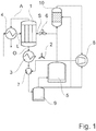
- Fig. 1 is an integrated oxygen generation in biomass gasification by vacuum extraction of an oxygen membrane module heated directly with synthesis gas with minimized electrical energy consumption with its essential components.
- the membrane module 1 for generating oxygen in the biomass gasification is equipped with 2500 BSCF membrane tubes (BSCF - Ba 0.5 Sr 0.5 Co 0.8 Fe 0.2 O 3- ⁇ ) with a length of 700 mm.
- the BSCF membrane tubes closed on one side have one Outside diameter of 3.2 mm and an inside diameter of 2.6 mm and are inserted in a vacuum-tight connection plate with silicone push-in seals.
- the membrane module 1 is supplied with fresh air L by a radial fan or side channel compressor 2.
- the fresh air L is passed through a first heat exchanger 3 for cooling the generated oxygen O and preheated by the exhaust gas A emerging from the membrane module 1 via a second heat exchanger 4.
- the residual heat required to reach the operating temperature is supplied by synthesis gas S from the carburetor 5 via a controllable gas valve 6.
- the oxygen produced is extracted by a vacuum pump 7 which is mechanically coupled to the gas engine of the CHP 8.
- a vacuum pump 7 which is mechanically coupled to the gas engine of the CHP 8.
- an electromechanical vacuum pump or a steam jet pump can be used.
- these pumps require a pumping speed of 150 suction m 3 / h.
- the oxygen is temporarily stored in a tank 9 and is available for gasification in the carburetor 5, for the gas cleaning device 10 and for use in the gas engine of the CHP 8.
- the membrane module 1 At an operating temperature of the membrane module 1 of 850 ° C., an extraction pressure of 90 mbar on the suction side of the vacuum pump 7 and an air throughput of 260 m 3 iN / h, the membrane module 1 generates 13 m 3 iN O 2 per hour.
- Fig. 2 a process diagram for the generation of an oxygen-steam mixture by means of an oxygen membrane module heated directly with the synthesis gas S is shown.
- the membrane module 1 for generating oxygen in the biomass gasification is equipped with 1000 BSCF membrane tubes (BSCF - Ba 0.5 Sr 0.5 Co 0.8 Fe 0.2 O 3- ⁇ ) with a length of 700 mm.
- Water vapor from a first steam generator 11 is introduced into the pipes closed on one side with an outer diameter of 10 mm and an inner diameter of 8 mm via flushing lances.
- the low oxygen partial pressure in the water vapor leads to the water vapor W being enriched with oxygen O.
- the BSCF membrane pipes and flushing lances are sealed in a vacuum-tight connection plate with O-ring compression fittings.
- the membrane module 1 is supplied with fresh air L by the radial fan or side channel compressor 2.
- the fresh air L is passed through a condenser 13 to cool the gas mixture generated from oxygen O and steam.
- the second heat exchanger 4 arranged downstream of the condenser 13 further heats up the fresh air L flowing through by passing the exhaust gas A emerging from the membrane module 1 over the second heat exchanger 4.
- the supply of the residual heat required to reach the operating temperature takes place through the synthesis gas S from the carburetor 5 via a controllable gas valve 6.
- the oxygen O is separated from the water and fed to the tank 9.
- the condensed water in the liquid separator 14 is again fed to the first steam generator 11 and second steam generator 12.
- the oxygen O in the tank 9 is available for the gasification in the carburetor 5, for the gas cleaning device 10 and for use in the gas engine of the CHP 8, the water content of the oxygen O being due both to the temperature of the condenser 13 and to the admixture of steam can be set from the steam generators (11, 12).
- the membrane module At an operating temperature of membrane module 1 of 850 ° C and a throughput of 50 m 3 iN steam per hour at approx. 1.1 bar to 1.8 bar steam pressure, the membrane module generates 1 5 m 3 iN O 2 per hour, without electrical energy to consume.
- Fig. 3 is the basic structure of the membrane module 1 according to the design according to the explanations Fig. 1 is shown, with only a single membrane tube 15 being shown instead of the 2500 BSCF membrane tubes.
- the essential components of the membrane module 1 are thus the membrane tube 15, the protective tube 16 placed over it and the surrounding housing 17 with its metallic connecting plate 18.
- the introduction of the fresh air L into the space 24 between the membrane tube 15 and the protective tube 16 takes place in the foot region of the protective tube 16. Because of the insulation 19, only a little heat can be transferred to the connection plate 18, so that the gas discharge outlet 20 for the oxygen O obtained from the membrane tube 15 is not additionally heated.
- the protective tube 16 prevents direct contact of the combustion products in operation by bringing the gas velocity at the outlet opening 21 into the combustion chamber 22 to over 0.2 m / s by adjusting the air throughput. As a result, backflow of the combustion gases to the membrane tube 15 can be largely avoided.
- Fig. 3 schematically shows the basic structure of the membrane module 1 according to the embodiment in accordance with the explanations Fig. 2 , whereby here too analogous to the explanations for Fig. 3 only a single membrane tube 15 is shown.
- the essential components of the membrane module 1 are thus the membrane tube 15, the protective tube 16 placed over it, the surrounding housing 17 with its metallic connection plate 18 and the internal flushing lance 23.
- the purge lance 23 is only required when using water vapor W as the purge gas.
- the exhaust air can also be recirculated without entering the combustion chamber 22, but this requires a more complex design solution. In this case, the combustion air must be supplied separately. The management of the gases becomes more complicated because the hot, oxygen-depleted air must then also be discharged via the connection plate 18 or further outlet openings 21 must be provided for the outlet of the oxygen-depleted air. In this case, it makes sense to integrate the fresh air exhaust gas heat exchanger into the connection plate 18 of the membrane module 1.
Landscapes
- Chemical & Material Sciences (AREA)
- Organic Chemistry (AREA)
- Engineering & Computer Science (AREA)
- Combustion & Propulsion (AREA)
- Oil, Petroleum & Natural Gas (AREA)
- Chemical Kinetics & Catalysis (AREA)
- Analytical Chemistry (AREA)
- Inorganic Chemistry (AREA)
- Separation Using Semi-Permeable Membranes (AREA)
Description
- Die Erfindung betrifft ein Verfahren und ein Membranmodul zur prozessintegrierten Sauerstofferzeugung bei der Biomassevergasung, wobei der Sauerstoff über gemischt leitende keramische Membranen bei hoher Temperatur erzeugt wird.
- Die Biomassevergasung mit Luft liefert ein stickstoffhaltiges Synthesegas, dessen Heizwert in der Regel nicht mehr als 1,8 kWh je m3 i.N. (im Normzustand, nach DIN 1343) beträgt. Dieser Wert ist auch bei Verwendung idealer Rohstoffqualitäten, z. B. trockener Buchenholz-Hackschnitzel, nicht zu übertreffen. Die für Synthese- und Mischgase entwickelten Gasmotoren erreichen mit derartigen Schwachgasen nur geringe elektrische Wirkungsgrade, so dass eine Stromerzeugung damit nicht wettbewerbsfähig ist. Zur Erhöhung des Heizwertes können Gase mit höherem Heizwert zugemischt werden, z. B. Biomethan oder Erdgas, was jedoch die Brennstoffkosten deutlich erhöht. Als Alternative zur Vergasung mit Luft werden deshalb größere Vergasungsanlagen mit Sauerstoff betrieben, dem aufgrund der resultierenden hohen Vergasungstemperaturen häufig Dampf zur Kühlung zugemischt wird (
WO 2008/068596 A2 ). - Das Synthesegas aus der Biomassevergasung enthält je nach dem verwendeten Vergasertyp unterschiedliche Anteile an Teer, die vor der Nutzung im Blockheizkraftwerk, in dieser Schrift durchgängig mit "BHKW" bezeichnet, entfernt werden müssen. Eine sichere Methode zur Teerentfernung ist die Nacherhitzung des Synthesegases auf ca. 1200 °C, was relativ einfach durch Zugabe von Sauerstoff ins heiße Synthesegas erreicht werden kann. Darüber hinaus kann Sauerstoff auch eingesetzt werden, um die elektrische Leistung von Gasmotoren oder Brennstoffzellen zu erhöhen, indem z. B. der Sauerstoffgehalt der zugeführten Verbrennungsluft erhöht wird.
- Die konventionelle Produktion von Sauerstoff erfolgt bevorzugt durch Druckwechseladsorption (PSA - Pressure Swing Adsorption) oder durch kryogene Luftzerlegung (Linde®-Verfahren). Energetisch optimierte Großanlagen erreichen spezifische Energieverbräuche von minimal 0,4 kWhel./ m3 i.N. O2 (kryogen) bzw. 0,36 kWhel./ m3 i.N. O2 (PSA). Die Biomassevergasung benötigt jedoch nur vergleichsweise geringe Sauerstoffmengen, die üblicherweise durch kleinere PSA-Anlagen bereitgestellt werden. Diese PSA-Anlagen benötigen deutlich mehr als 1,0 kWhel./ m3 i.N. O2 und schmälern damit durch ihren Eigenbedarf an elektrischer Energie erheblich den wirtschaftlichen Ertrag der Vergasungsanlage bzw. machen diese unwirtschaftlich. Die Verwendung von Sauerstoff aus Flaschen oder Flüssigtanks bringt erhebliche Aufwendungen für Miete und Transport mit sich und hat sich deshalb bisher ebenfalls nicht durchgesetzt.
- Eine alternative Methode zur Herstellung von Sauerstoff basiert auf einem Membrantrennprozess bei hohen Temperaturen. Dafür werden gemischt leitende keramische Membranen (MIEC - Mixed Ionic Electronic Conductor) eingesetzt, die eine hochselektive Abtrennung von Sauerstoff ermöglichen. Der Sauerstofftransport beruht auf dem Transport von Oxidionen durch das gasdichte keramische Material und dem parallel stattfindenden Transport elektronischer Ladungsträger (Elektronen oder Defektelektronen). Seit den 1980er Jahren wurde eine Vielzahl keramischer Materialien hinsichtlich des Sauerstofftransports und weiterer Materialeigenschaften untersucht (Sunarso, J., Baumann, S, Serra, J.M., Meulenberg, W.A., Liu, S., Lin, Y.S., Diniz da Costa, J.C.: Mixed ionic-electronic conducting (MIEC) ceramic-based membranes for oxygen separation. J. of Membrane Sc. 320 (2008), 13 - 41).
- Die Sauerstoffpermeation durch eine MIEC-Membran kann durch die Wagner'sche Gleichung beschrieben werden und ist vor allem durch die ambipolare Leitfähigkeit des Materials bei Einsatztemperatur, die Membrandicke und durch die Triebkraft bestimmt. Letztere ergibt sich aus dem logarithmischen Verhältnis des Sauerstoffpartialdrucks im Feedgas (ph) zu dem Sauerstoffpartialdruck im Spülgas (pl) oder im Permeat. Der Sauerstofffluss durch eine MIEC-Membran ist demnach bei gegebenem Material, konstanter Membrandicke und festgelegter Temperatur proportional zu In(ph/pl). Dementsprechend hat eine Verdopplung von ph auf der Feedgasseite die gleiche Erhöhung des Sauerstoffflusses zur Folge wie eine Halbierung von pl auf der Permeat- oder Sweepgasseite. Zur Erzeugung reinen Sauerstoffs in technischen Membrananlagen kann dementsprechend die Luft verdichtet oder der Sauerstoff mit Vakuum abgesaugt werden, natürlich sind auch kombinierte Prozesse möglich (Armstrong, P.A., Bennett, D.L., Foster, E.P., Stein, V.E.: The New Oxygen Supply for the New IGCC Market. Gasification Techn. 2005, San Francisco, 9.-12.10.2005). Für großtechnische Anlagen wird die Verdichtung der Luft bevorzugt (
US 6,139,604 ), da Kompressoren im Allgemeinen billiger und besser verfügbar sind als Vakuumerzeuger. - Im Membrantrennprozess kann der Restsauerstoffgehalt der Sauerstoffabgereicherten Abluft noch genutzt werden, um die MIEC-Membranen und den Abluftstrom zu beheizen (
US 2005/0037299 A1 ). Da die bisher vorgeschlagenen Anordnungen durchweg einen direkten Kontakt der Membran zum Rauchgas durch Konvektion und Diffusion in der Gasphase ermöglichen, sind die vorgeschlagenen Anordnungen jedoch nur für CO2-stabile MIEC-Membranen geeignet. Diese weisen typischerweise nur sehr geringe Sauerstoffdurchsätze auf, führen zum Einsatz großer Membranflächen, großen Reaktoren und hohen Kosten. Sie sind für die kleinskalige Sauerstoffproduktion deshalb nicht geeignet. - Wird der erzeugte Sauerstoff für chemische Reaktionen benötigt, so kann die Triebkraft energetisch am günstigsten durch die Spülung der MIEC-Membran mit sauerstoffarmen Gasen erzeugt werden. Der Oxycoal-AC-Prozess (http://www.oxycoal-ac.de/index.php?id=1099&L=0) für ein Kohlekraftwerk, d. h. die Verbrennung von Kohle in einem CO2/O2-Gemisch, verwendet deshalb das rezirkulierte Rauchgas als Spülgas an der MIEC-Membran, da dieses lediglich Sauerstoffgehalte von 1 - 3 Vol-% aufweist. Um den Sauerstofffluss durch die Membran zu steigern, wird auf der Feedgasseite die Luft komprimiert und nach dem Membranmodul die Kompressionsenergie durch eine Entspannungsturbine zu einem Großteil zurückgewonnen. Die Minimierung der Energieverluste erfordert dabei einen hohen Wirkungsgrad von Verdichter und Turbine. Außerdem ist zur Realisierung eines günstigen Belastungszustandes der keramischen Membrankomponenten ein äußerer Druckkessel erforderlich.
- Die gegenwärtig verfügbaren MIEC-Membranmaterialien mit hoher Sauerstoffpermeation sind unter CO2 nicht stabil, da die enthaltenen Erdalkalien mit dem CO2 Carbonate bilden und die Membranoberfläche blockieren (Schulz, M., Kriegel, R., Kämpfer, A.: Assessment of CO2-stability and oxygen flux of oxygen permeable membranes. J. Membr. Sc. 378 (2011), S. 10-17). Deshalb werden alternativ zum Oxycoal-AC-Prozess mit CO2-Sweep, der auch als 4-End-Verfahren bezeichnet wird, Prozesse ohne Sweepgas entwickelt. Diese werden als Dead-End oder 3-End-Verfahren bezeichnet. Dabei wird, wie bereits ausgeführt, durch Erzeugen von Druckunterschieden reiner Sauerstoff erzeugt.
- Im Bereich der Energieerzeugung beanspruchen mehrere Patente den Einsatz von MIEC-Membranen für die Oxyfuel-Verbrennung im Kohlekraftwerk (Hashim, S.S. et al: "Oxygen seperation from air using ceramic-based membrane technology for sustainable fuel produktion and power generation", Renwable and Sustainable Energy Reviews, ELSEVIERS SCIENCE, New York, NY, US, Bd. 15, Nr.2, 1. Februar 2011, Seiten 1284-1293, XP027582285, ISSN: 1364-0321) mit dem Ziel der CO2-Abtrennung (
WO 2009/065374 A3 ,EP 2 026 004 A1 ). Verschiedene Verfahrensschemata zielen vor allem darauf ab, die zu erwartenden Wirkungsgradeinbußen möglichst zu minimieren. InWO 2009/065374 A3 wird im Gegensatz zu den meist präferierten Überdruckprozessen Vakuum auf der Permeatseite angelegt. Dies ermöglicht ein Membranmodul ohne hochtemperaturfesten äußeren Druckkessel und erfordert geringere Kompressionsenergie, da nur der Sauerstoff auf der Permeatseite der Membran verdichtet werden muss. Nachteilig ist, dass die Kompressionsenergie dem Gesamtprozess verloren geht. - Die Erzeugung von Sauerstoff über MIEC-Membranen und dessen Einsatz im Vergasungskraftwerk beanspruchen
WO 2008/014481 A1 undEP 2 067 937 A2 . In beiden Patenten wird die ins Membranmodul eintretende Luft verdichtet und die Kompressionsenergie durch Entspannungsturbinen zurückgewonnen. - Für die Biomassevergasung ist der Einsatz von MIEC-Membranen zur Sauerstoff-Erzeugung nur dann sinnvoll, wenn der Energieverbrauch typischer PSA-Anlagen deutlich unterschritten werden kann. Der Eigenenergiebedarf der MIEC-Membrantrennung resultiert einerseits aus der Wärmeenergie, die zur Aufrechterhaltung der hohen Temperatur von 800 - 900 °C an der Membran erforderlich ist. Andererseits wird zur Erzeugung der Triebkraft für den Sauerstofftransport Kompressionsenergie zur Gasverdichtung benötigt. Erschwerend für die wärmetechnische Integration wirkt sich aus, dass bisher bekannte MIEC-Membranmaterialien mit hohem Sauerstofffluss meist nur in einem eingeschränkten Temperaturbereich einsetzbar sind. So tendiert das häufig eingesetzte Material BSCF unterhalb von ca. 830 °C zu einem langsamen Phasenzerfall, der zu einem Nachlassen der Sauerstoffpermeation führt (Shao, Z., Yang, W., Cong, Y., Dong, H., Tong, J., Xiong, G.: Investigation of the permeation behavior and stability of a Ba0.5Sr0.5Co0.8Fe0.2O3-δ oxygen membrane. J. of Membr. Sc. 172 (2000), S. 177-188). Mit steigender Temperatur nimmt außerdem die Kriechrate des Materials zu, so dass es aufgrund der anliegenden Druckunterschiede an der Membran zum mechanischen Versagen der Membrankomponenten kommen kann (Pecanac, G., Baumann, S., Malzbender, J.: Mechanical properties and lifetime predictions for Ba0.5Sr0.5Co0.8Fe0.2O3-δ membrane material, J. of Membr. Sc. 385- 386 (2011), S. 263- 268). Ein direkter Kontakt mit Synthesegas führt darüber hinaus zu starker Korrosion (Lu, H., Tong, J., Cong, Y., Yang, W.: Partial oxidation of methane in Ba0.5Sr0.5Co0.8Fe0.2O3-δ membrane reactor at high pressures. Catalysis Today 104 (2005), S. 154-159) und u. U. zum Bruch der Membranen. Eine direkte Beheizung der Membranen mit Verbrennungsgasen erscheint ebenfalls nicht möglich, da der CO2-Gehalt im Rauchgas zur Bedeckung der Membran mit Erdalkalicarbonaten und zur Blockade der Sauerstoffpermeation führt (Arnold, M., Wang, H., Feldhoff, A.: Influence of CO2 on the oxygen permeation performance and the microstructure of perovskite-type (Ba0.5Sr0.5)(Co0.8Fe0.2)O3-δ membranes. J. of Membr. Sc. 293 (2007), S. 44-52).
- Die aufgeführten nachteiligen Eigenschaften bzw. die eingeschränkten Einsatzbedingungen hochentwickelter MIEC-Membranmaterialien führen somit zu erheblichen Einschränkungen bei der technischen Realisierung eines prozessintegrierten Membranmoduls zur Sauerstofferzeugung. Es verbleibt lediglich die Möglichkeit, die ins Membranmodul eintretenden Gasströme entsprechend genau zu temperieren oder das Membranmodul mit elektrischen Zusatzheizungen zu versehen, um den Betrieb im optimalen Temperaturbereich sicherzustellen und einen Kontakt mit korrosiv wirkenden Gasen zu vermeiden. Dies würde jedoch zu aufwändigen, hochkomplexen Anlagensteuerungen oder zu einem hohen zusätzlichen Verbrauch elektrischer Energie führen.
- Der Erfindung liegt die Aufgabe zugrunde, eine Möglichkeit zur energieeffizienten Sauerstofferzeugung in der Biomassevergasung zur Effizienzsteigerung des Gesamtprozesses anzugeben.
- Erfindungsgemäß werden die aufgeführten Nachteile des Standes der Technik dadurch gelöst, dass ein Membranmodul direkt mit dem Synthesegas aus der Biomassevergasung beheizt wird. Diese Beheizung soll jedoch nur weniger als 20 %, typischerweise weniger als 10 % und unter optimalen Bedingungen nur ca. 5 % des Wärmebedarfs des Membranmoduls abdecken. Der überwiegende Teil der zur Erhitzung der Frischluft erforderlichen Wärme wird der Abluft des Membranmoduls durch Wärmetausch entzogen. Dies ist durch Verwendung effizienter Rekuperatoren möglich, also von Hochtemperatur-Wärmetauschern auf Basis hochtemperaturfester Stähle. Alternativ können Regeneratoren mit keramischen Schüttungen oder Wabenstrukturen eingesetzt werden, die abwechselnd durch Frischluft und Abgas durchströmt werden. Auf diese Weise wird der Großteil des erforderlichen Wärmebedarfs unabhängig vom Prozess der Biomassevergasung durch Wärmerückgewinnung aus dem Abgas des Membranmoduls bereitgestellt.
- Die direkte Beheizung des Membranmoduls mit dem Synthesegas aus der Biomassevergasung führt zu einer einfachen Anbindung an die Vergasungsanlage und zeichnet sich durch ein sehr schnelles thermisches Ansprechverhalten und ein unkompliziertes Regelverhalten aus. Dadurch kann unabhängig von den verfügbaren Temperaturniveaus des Vergasungsprozesses eine Temperaturanhebung im Membranmodul auf dessen optimale Betriebstemperatur realisiert werden. Die anlagenspezifischen Besonderheiten der Biomassevergasungsanlage spielen bei Verwendung des direkt gasbeheizten Membranmoduls somit nur noch eine untergeordnete Rolle, so dass eine Einbindung an bestehende Anlagen stark vereinfacht wird. Darüber hinaus ist durch die Verbrennung innerhalb des Membranmoduls eine optimale Ausnutzung der zugeführten Energie des Synthesegases gegeben.
- Der Angriff der MIEC-Membranen durch korrosive Gasbestandteile, wie CO2 oder SO2 wird durch eine konstruktive Gestaltung der Gasströmung weitgehend verhindert bzw. eingeschränkt. Erfindungsgemäß wird die eintretende vorgewärmte Frischluft zunächst innerhalb von Schutzrohren an den darin befindlichen Membranrohren entlang geführt und tritt erst danach in den eigentlichen Verbrennungsraum ein. Die Austrittsöffnung der Schutzrohre wird zu diesem Zweck so bemessen, dass die in den Verbrennungsraum eintretende Frischluft innerhalb der Gasaustrittsöffnung mindestens eine Geschwindigkeit von 0,2 m/s erreicht. Gasförmige Verbrennungsprodukte werden dadurch vom Membranmaterial weitgehend ferngehalten. Die Verbrennung des Synthesegases erfolgt somit räumlich und zeitlich erst nach dem Kontakt der Frischluft mit der Membran, die Verbrennung findet also mit der an Sauerstoff abgereicherten Luft statt. Für den Membrantrennprozess steht somit auf der Feedseite der Membran der unbeeinflusste Sauerstoff-Partialdruck der eintretenden Frischluft und damit die volle Triebkraft zur Verfügung, was zu einer maximalen Sauerstoffproduktionsrate führt. Durch konstruktive Gestaltung der Austrittsöffnung als Düse können je nach den technologischen Erfordernissen sogar der Luftdruck im Schutzrohr und damit die Sauerstoffpermeation weiter erhöht werden, ohne dass dafür ein äußerer Druckkessel erforderlich ist.
- Die Triebkraft für den Sauerstofftransport wird erfindungsgemäß durch Erzeugen eines Vakuums innerhalb der Membrankomponenten oder durch Spülen der Membranen mit Wasserdampf erzeugt. Zur Vakuumerzeugung können elektromechanische Vakuumpumpen, mechanische Vakuumpumpen oder Dampfstrahlpumpen eingesetzt werden. Mechanische Vakuumpumpen, z. B. Flüssigkeitsringpumpen, werden vorteilhaft mit dem Gasmotor mechanisch gekoppelt, um die Verluste bei der Umwandlung in elektrische Energie und zurück in die elektromechanische Vakuumerzeugung zu vermeiden. Gegenüber elektromechanischen Pumpen kann so der Eigenenergiebedarf der Sauerstofferzeugung weiter verringert werden. Stehen keine Abnehmer für die überschüssige Wärmeenergie zur Verfügung, so kann die Abwärme zur Dampferzeugung genutzt werden. Der Dampf wiederum kann mittels einer Dampfstrahlpumpe zur Vakuumerzeugung eingesetzt werden, so dass weder elektrische noch mechanische Energie zur Erzeugung der Triebkraft für den Sauerstofftransport erforderlich ist. Dadurch wird erfindungsgemäß eine prozessintegrierte Sauerstofferzeugung ohne Eigenbedarf an elektrischer Energie realisiert, was gegenüber üblichen PSA-Anlagen einen bedeutenden technologischen und wirtschaftlichen Vorteil darstellt.
- Bei der Nutzung einer Dampfstrahlpumpe fällt wie bei der Spülung der Membranen mit Wasserdampf Sauerstoff mit hohem Wasserdampfanteil an. Der Wasseranteil des Sauerstoffs kann eingesetzt werden, um die Temperatur in der Vergasungszone zu regulieren, da bei der Vergasung mit reinem Sauerstoff sehr hohe Temperaturen erreicht werden. Eine Einstellung des Dampf zu Sauerstoffverhältnisses ist durch Auskondensation des überschüssigen Wasserdampfes oder Zumischen von Dampf einfach realisierbar.
- Insbesondere wird die Aufgabe auch durch die Einbindung eines Membranmoduls mit einem Gehäuse und einer BSCF-Membran in die Biomassevergasung dadurch gelöst, dass das Gehäuse mit einem Eingang für Brenngas oder Synthesegas und einem Ausgang für Abgas im unteren Bereich mit einer Anschlussplatte und einer darüber liegenden Isolierung versehen ist, dass die BSCF-Membran aus einer Vielzahl von oben geschlossenen und unten geöffneten Membranrohren besteht, wobei die unten geöffneten Membranrohre durch die Isolierung hindurch zu einem in der Anschlussplatte befindlichen gemeinsamen Gasabführungsausgang zum Abzug mindestens des gewonnenen Sauerstoffs geführt sind, dass mindestens ein Schutzrohr vorhanden ist, welches über ein oder ein Teil oder alle Membranrohre gestülpt angeordnet ist und im unteren Bereich mindestens mit der Isolierung in Kontakt steht, so dass zwischen Membranrohren und Schutzrohr ein Zwischenraum und zwischen Schutzrohr und Gehäuse ein Verbrennungsraum gebildet sind, wobei in den im unteren Bereich des Zwischenraums Frischluft und in den Verbrennungsraum Brenngas oder Synthesegas zuführbar sind, und dass das Schutzrohr im oberen Bereich eine Austrittsöffnung zum Verbrennungsraum hin aufweist, die derart geöffnet ist, dass die Frischluftgeschwindigkeit an der Austrittsöffnung größer 0,2 m/s ist.
- Die Erfindung soll nachstehend anhand von Ausführungsbeispielen näher erläutert werden. In den dazugehörigen Zeichnungen zeigt
- Fig. 1
- eine Einbindung eines Membranmoduls in die Biomassevergasung und Möglichkeiten der Sauerstoffnutzung in der Biomassevergasung,
- Fig. 2
- eine weitere Einbindungsmöglichkeit eines Membranmoduls in die Biomassevergasung und Möglichkeiten der Sauerstoffnutzung in der Biomassevergasung,
- Fig. 3
- eine schematische Darstellung einer möglichen Einbindung der Membranrohre in das direkt beheizte Membranmodul und
- Fig. 4
- eine weitere schematische Darstellung einer möglichen Einbindung der Membranrohre in das direkt beheizte Membranmodul.
- Gemäß
Fig. 1 ist eine integrierte Sauerstofferzeugung in der Biomassevergasung durch Vakuumabsaugung eines direkt mit Synthesegas beheizten Sauerstoff-Membranmoduls mit minimiertem elektrischem Energiebedarf mit seinen wesentlichen Bestandteilen dargestellt. - Das Membranmodul 1 zur Sauerstofferzeugung in der Biomassevergasung ist mit 2500 BSCF-Membranrohren (BSCF - Ba0,5Sr0,5Co0,8Fe0,2O3-δ) der Länge 700 mm bestückt. Die einseitig geschlossenen BSCF-Membranrohre besitzen einen Außendurchmesser von 3,2 mm und einen Innendurchmesser von 2,6 mm und sind in eine vakuumdichte Anschlussplatte mit Silikon-Einsteckdichtungen vakuumdicht eingesetzt. Das Membranmodul 1 wird durch einen Radiallüfter oder Seitenkanalverdichter 2 mit Frischluft L versorgt. Die Frischluft L wird zur Kühlung des erzeugten Sauerstoffs O über einen ersten Wärmetauscher 3 geführt und durch das aus dem Membranmodul 1 austretende Abgas A über einen zweiten Wärmetauscher 4 vorgewärmt. Die Zuführung der erforderlichen Restwärme zum Erreichen der Betriebstemperatur erfolgt durch Synthesegas S aus dem Vergaser 5 über ein steuerbares Gasventil 6. Die Absaugung des entstehenden Sauerstoffs erfolgt mit einer Vakuumpumpe 7, die mit dem Gasmotor des BHKW 8 mechanisch gekoppelt ist. Alternativ kann eine elektromechanische Vakuumpumpe oder eine Dampfstrahlpumpe eingesetzt werden. Für die Erzeugung der nachfolgend beschriebenen Sauerstoffflüsse benötigen diese Pumpen ein Saugvermögen von 150 Saug-m3/h. Der Sauerstoff wird in einem Tank 9 zwischengespeichert und steht für die Vergasung im Vergaser 5, für die Gasreinigungsvorrichtung 10 und für die Nutzung im Gasmotor des BHKW 8 zur Verfügung. Bei einer Betriebstemperatur des Membranmoduls 1 von 850 °C, einem Entnahmedruck von 90 mbar auf der Saugseite der Vakuumpumpe 7 und einem Luftdurchsatz von 260 m3 i.N./h erzeugt das Membranmodul 1 13 m3 i.N. O2 pro Stunde.
- Bei Verwendung einer elektromechanischen Vakuumpumpe wird unter Vernachlässigung der thermischen Verluste ein spezifischer Verbrauch an Elektroenergie von 0,22 kWhel./m3 i.N. O2 erreicht. Die mechanische Kopplung der Vakuumpumpe 7 mit dem Gasmotor des BHKW 8 benötigt keine elektrische Energie zur Sauerstoff-Erzeugung, allerdings wird dem BHKW mechanische Energie zum Betrieb der Vakuumpumpe 7 entzogen.
- Gemäß
Fig. 2 ist ein Verfahrensschema zur Erzeugung von einem Sauerstoff-Dampf-Gemisch mittels eines direkt mit dem Synthesegas S beheizten Sauerstoff-Membranmoduls dargestellt. - Das Membranmodul 1 zur Sauerstofferzeugung in der Biomassevergasung ist mit 1000 BSCF-Membranrohren (BSCF - Ba0,5Sr0,5Co0,8Fe0,2O3-δ) der Länge 700 mm bestückt. In die einseitig geschlossenen Rohre mit einem Außendurchmesser von 10 mm und einen Innendurchmesser von 8 mm wird Wasserdampf aus einem ersten Dampferzeuger 11 über Spüllanzen eingeleitet. Der niedrige Sauerstoffpartialdruck im Wasserdampf führt zur Anreicherung des Wasserdampfes W mit Sauerstoff O. Die BSCF-Membranrohre und Spüllanzen sind in eine vakuumdichte Anschlussplatte mit O-Ring-Quetschverschraubungen eingedichtet. Dem mit heißem Synthesegas S aus dem Vergaser 5 betriebenen ersten Dampferzeuger 11 kann ein zweiter Dampferzeuger 12 vorgelagert sein, der die Abwärme des Gasmotors des BHKW 8 nutzt. Das Membranmodul 1 wird durch den Radiallüfter oder Seitenkanalverdichter 2 mit Frischluft L versorgt. Die Frischluft L wird zur Kühlung des erzeugten Gasgemisches aus Sauerstoff O und Dampf über einen Kondensator 13 geführt. Der dem Kondensator 13 nachgeordnete zweite Wärmetauscher 4 wärmt die durchströmende Frischluft L weiter auf, indem das aus dem Membranmodul 1 austretende Abgas A über den zweiten Wärmetauscher 4 geführt wird. Die Zuführung der erforderlichen Restwärme zum Erreichen der Betriebstemperatur erfolgt durch das Synthesegas S aus dem Vergaser 5 über ein steuerbares Gasventil 6. In dem dem Kondensator 13 nachgeordneten Flüssigkeitsabscheider 14 wird der Sauerstoff O vom Wasser getrennt und dem Tank 9 zugeleitet. Das auskondensierte Wasser im Flüssigkeitsabscheider 14 wird erneut dem ersten Dampferzeuger 11 und zweiten Dampferzeuger 12 zugeführt. Der Sauerstoff O im Tank 9 steht für die Vergasung im Vergaser 5, für die Gasreinigungsvorrichtung 10 und für die Nutzung im Gasmotor des BHKW 8 zur Verfügung, wobei der Wassergehalt des Sauerstoffs O sowohl durch die Temperatur des Kondensators 13 als auch durch die Zumischung von Dampf aus den Dampferzeugern (11, 12) eingestellt werden kann. Bei einer Betriebstemperatur des Membranmoduls 1 von 850 °C und einem Durchsatz von 50 m3 i.N. Dampf pro Stunde bei ca. 1,1 bar bis 1,8 bar Dampfdruck erzeugt das Membranmodul 1 5 m3 i.N. O2 pro Stunde, ohne elektrische Energie zu verbrauchen.
- Gemäß
Fig. 3 ist der Prinzipaufbau des Membranmoduls 1 gemäß der Ausführung entsprechend den Erläuterungen zuFig. 1 dargestellt, wobei statt der 2500 BSCF-Membranrohre nur ein einziges Membranrohr 15 dargestellt ist. Als die wesentlichen Bestandteile des Membranmoduls 1 sind somit das Membranrohr 15, das darüber gestülpte Schutzrohr 16 sowie das umschließende Gehäuse 17 mit seiner metallischen Anschlussplatte 18 erkennbar. Die Einleitung der Frischluft L in den Zwischenraum 24 zwischen Membranrohr 15 und Schutzrohr 16 erfolgt im Fußbereich des Schutzrohres 16. Aufgrund der Isolierung 19 kann nur wenig Wärme auf die Anschlussplatte 18 übertragen werden, so dass der Gasabführausgang 20 für den gewonnenen Sauerstoff O des Membranrohrs 15 nicht zusätzlich mit aufgeheizt wird. - Das Schutzrohr 16 verhindert im Betrieb einen direkten Kontakt der Verbrennungsprodukte, indem durch Einstellung des Luftdurchsatzes die Gasgeschwindigkeit an der Austrittsöffnung 21 in den Verbrennungsraum 22 auf über 0,2 m/s gebracht wird. Dadurch kann ein Rückströmen der Verbrennungsgase an das Membranrohr 15 weitgehend vermieden werden.
- Alternativ zur Ausführung gemäß
Fig. 3 ist es auch möglich, mehrere kleinere Austrittsöffnungen 21 im Schutzrohr 16 zu verwenden oder poröse keramische Schutzrohre 16 mit einer offenen Porosität von 8 Vol-% bis 25 Vol-% einzusetzen. Bei höheren Luftdurchsätzen kann direkt ein offenes Schutzrohr 16 ohne Verengung verwendet werden, wenn die entsprechende Gasgeschwindigkeit von mehr als 0,2 m/s eingehalten wird. Auch die Anordnung mehrerer Membranrohre 15 in einem größeren Schutzrohr 16 ist möglich.Fig. 4 zeigt schematisch den Prinzipaufbau des Membranmoduls 1 gemäß der Ausführung entsprechend den Erläuterungen zuFig. 2 , wobei auch hier analog zu den Erläuterungen zuFig.3 nur ein einziges Membranrohr 15 dargestellt ist. Als die wesentlichen Bestandteile des Membranmoduls 1 sind somit das Membranrohr 15, das darüber gestülpte Schutzrohr 16, das umschließende Gehäuse 17 mit seiner metallischen Anschlussplatte 18 sowie die innenliegende Spüllanze 23 erkennbar. Die Spüllanze 23 ist nur bei Verwendung von Wasserdampf W als Spülgas erforderlich. Wie einfach ersichtlich ist, kann auch eine Rückführung der Abluft ohne Eintritt in den Verbrennungsraum 22 erfolgen, was jedoch eine aufwändigere konstruktive Lösung erfordert. In diesem Fall muss die Verbrennungsluft separat zugeführt werden. Das Management der Gase wird dadurch komplizierter, da dann auch die heiße, sauerstoffverarmte Luft über die Anschlussplatte 18 abgeführt werden muss oder für den Austritt der sauerstoffverarmten Luft weitere Austrittsöffnungen 21 angebracht werden müssen. In diesem Fall ist es sinnvoll, den Frischluft-Abgas-Wärmetauscher in die Anschlussplatte 18 des Membranmoduls 1 zu integrieren. -
- 1
- Membranmodul
- 2
- Radiallüfter oder Seitenkanalverdichter
- 3
- erster Wärmetauscher
- 4
- zweiter Wärmetauscher
- 5
- Vergaser
- 6
- steuerbares Gasventil
- 7
- Vakuumpumpe
- 8
- Gasmotor des BHKW
- 9
- Tank
- 10
- Gasreinigungsvorrichtung
- 11
- erster Dampferzeuger
- 12
- zweiter Dampferzeuger
- 13
- Kondensator
- 14
- Flüssigkeitsabscheider
- 15
- Membranrohr
- 16
- Schutzrohr
- 17
- Gehäuse
- 18
- Anschlussplatte
- 19
- Isolierung
- 20
- Gasabführausgang
- 21
- Austrittsöffnung
- 22
- Verbrennungsraum
- 23
- Spüllanze
- 24
- Zwischenraum
- L
- Frischluft
- S
- Synthesegas
- A
- Abgas
- O
- Sauerstoff
- W
- Wasserdampf
Claims (6)
- Membranmodul (1) mit einem Gehäuse und einer mischleitenden, Sauerstoff-permeablen Membran, dadurch gekennzeichnet, dass- das Gehäuse (17) mit einem Eingang für Brenn- oder Synthesegas (S) und einem Ausgang für Abgas (A) sowie im unteren Bereich mit einer Anschlussplatte (18) und einer darüber liegenden Isolierung (19) versehen ist,- die mischleitende, Sauerstoff-permeable Membran aus einer Vielzahl von einseitig geschlossenen und auf der anderen Seite geöffneten Membranrohren (15) besteht, wobei das offene Ende der Membranrohre (15) durch die Isolierung (19) hindurch zu einem in der Anschlussplatte (18) befindlichen gemeinsamen Gasabführungsausgang (20) zum Abzug mindestens des gewonnenen Sauerstoffs (O) geführt sind,- mindestens ein Schutzrohr (16) vorhanden ist, welches über ein oder ein Teil oder alle Membranrohre (15) gestülpt angeordnet ist und auf einer Seite mindestens mit der Isolierung (19) in Kontakt steht, so dass zwischen Membranrohren (15) und Schutzrohr (16) ein Zwischenraum (24) und zwischen Schutzrohr (16) und Gehäuse (17) ein Verbrennungsraum (22) gebildet sind, wobei in den Zwischenraum (24) Frischluft (L) und in den Verbrennungsraum (22) Brenn- oder Synthesegas (S) zuführbar sind, und- das Schutzrohr (16) eine Austrittsöffnung (21) zum Verbrennungsraum (22) hin aufweist, die derart geöffnet ist, dass die Frischluftgeschwindigkeit an der Austrittsöffnung (21) größer 0,2 m/s ist.
- Membranmodul nach Anspruch 1, dadurch gekennzeichnet, dass innerhalb jedes Membranrohres (15) jeweils zum Spülen mit Wasserdampf (W) eine rohrartige Spüllanze (23) angeordnet ist.
- Membranmodul nach Anspruch 1 oder 2, dadurch gekennzeichnet, dass die mischleitende Membran eine BSCF-Membran ist.
- Verfahren zur energieeffizienten Sauerstofferzeugung in der Biomassevergasung unter Verwendung eines Membranmoduls (1) gemäß Anspruch 1 bis 3 zur Erzeugung von hochreinem Sauerstoff, dadurch gekennzeichnet, dass- mittels Rekuperatoren oder Regeneratoren die aus dem Membranmodul (1) austretenden Gase zur Erwärmung der eintretenden Frischluft (L) eingesetzt werden, wobei mehr als 50 % der im Abgas (A) enthaltenen Wärmeenergie zur Vorheizung der Frischluft (L) genutzt wird,- die vorgewärmte eintretende Frischluft (L) in einen Zwischenraum (24) des Membranmoduls (1) an den mischleitenden, Sauerstoff-permeablen Membranen vorbei geleitet wird, so dass Sauerstoff permeiert, der aus dem Membranmodul (1) herausgeführt wird,- die abgereicherte Frischluft (L) durch eine Austrittsöffnung (21) mit einer Geschwindigkeit größer 0,2 m/s aus den Zwischenraum (24) in einen um den Zwischenraum (24) herum angrenzenden Verbrennungsraum geleitet wird und- ein aus der Biomassevergasung gewonnenes Brenn- oder Synthesegas (S) zusammen mit der abgereicherten Frischluft (L) im Verbrennungsraum (22) des Membranmoduls (1) verbrannt wird, sodass das zur weiteren Verwendung vorgesehene Abgas (A) entsteht und gleichzeitig die entstehende Wärme in den Zwischenraum (24) gelangt und dort die mischleitenden, Sauerstoff-permeablen Membranen auf das erforderliche Temperaturniveau von 800 bis 900 °C aufheizt..
- Verfahren nach Anspruch 4, dadurch gekennzeichnet, dass ein Vakuum innerhalb der mischleitenden Membranen durch elektromechanische oder mechanische Vakuumpumpen (7) oder durch Dampfstrahlpumpen erzeugt wird.
- Verfahren nach den Ansprüchen 4 und 5, dadurch gekennzeichnet, dass das Brenn- oder Synthesegas (S) aus der Biomassevergasung in einen Gasmotor eines BHKW (8) eingespeist wird und die mechanische Vakuumpumpe (7) mit dem Gasmotor (8) mechanisch gekoppelt wird.
Applications Claiming Priority (2)
| Application Number | Priority Date | Filing Date | Title |
|---|---|---|---|
| DE102013103426.8A DE102013103426B4 (de) | 2013-04-05 | 2013-04-05 | Verfahren und Membranmodul zur energieeffizienten Sauerstofferzeugung in der Biomassevergasung |
| PCT/DE2014/100111 WO2014161531A2 (de) | 2013-04-05 | 2014-04-01 | Verfahren und membranmodul zur energieeffizienten sauerstofferzeugung in der biomassevergasung |
Publications (2)
| Publication Number | Publication Date |
|---|---|
| EP2981503A2 EP2981503A2 (de) | 2016-02-10 |
| EP2981503B1 true EP2981503B1 (de) | 2020-04-29 |
Family
ID=50896126
Family Applications (1)
| Application Number | Title | Priority Date | Filing Date |
|---|---|---|---|
| EP14728418.6A Active EP2981503B1 (de) | 2013-04-05 | 2014-04-01 | Verfahren und membranmodul zur energieeffizienten sauerstofferzeugung in der biomassevergasung |
Country Status (5)
| Country | Link |
|---|---|
| US (1) | US9725662B2 (de) |
| EP (1) | EP2981503B1 (de) |
| DE (1) | DE102013103426B4 (de) |
| PT (1) | PT2981503T (de) |
| WO (1) | WO2014161531A2 (de) |
Families Citing this family (5)
| Publication number | Priority date | Publication date | Assignee | Title |
|---|---|---|---|---|
| DE102014202190A1 (de) * | 2014-02-06 | 2015-08-06 | Fraunhofer-Gesellschaft zur Förderung der angewandten Forschung e.V. | Verfahren und Vorrichtung zum Erzeugen von elektrischer Energie durch Vergasung von Feststoffen, insbesondere Biomasse |
| DE102014115849A1 (de) * | 2014-10-30 | 2016-05-04 | Fraunhofer-Gesellschaft zur Förderung der angewandten Forschung e.V. | Verfahren und Anordnung zur Erzeugung und thermischen Kompression von Sauerstoff |
| US9834471B2 (en) * | 2015-11-17 | 2017-12-05 | King Fahd University Of Petroleum And Minerals | Sealing agent for ion transport membranes |
| DE102019128882B3 (de) * | 2019-10-25 | 2020-12-17 | Fraunhofer-Gesellschaft zur Förderung der angewandten Forschung e.V. | Verfahren zur prozessintegrierten Sauerstoff-Versorgung eines Wasserstoff-Kreislaufmotors mit Kreislaufführung eines Edelgases |
| DE102022203737B4 (de) | 2022-04-13 | 2024-05-08 | EAG Automatisierungsbau GmbH | Wasserstoff-Speicherkraftwerk und Verfahren zu dessen Betrieb |
Family Cites Families (19)
| Publication number | Priority date | Publication date | Assignee | Title |
|---|---|---|---|---|
| TW317588B (de) * | 1995-06-14 | 1997-10-11 | Praxair Technology Inc | |
| US5901547A (en) * | 1996-06-03 | 1999-05-11 | Air Products And Chemicals, Inc. | Operation method for integrated gasification combined cycle power generation system |
| US5820655A (en) * | 1997-04-29 | 1998-10-13 | Praxair Technology, Inc. | Solid Electrolyte ionic conductor reactor design |
| US5820654A (en) * | 1997-04-29 | 1998-10-13 | Praxair Technology, Inc. | Integrated solid electrolyte ionic conductor separator-cooler |
| US5935298A (en) * | 1997-11-18 | 1999-08-10 | Praxair Technology, Inc. | Solid electrolyte ionic conductor oxygen production with steam purge |
| US5954859A (en) * | 1997-11-18 | 1999-09-21 | Praxair Technology, Inc. | Solid electrolyte ionic conductor oxygen production with power generation |
| US6296686B1 (en) | 1998-06-03 | 2001-10-02 | Praxair Technology, Inc. | Ceramic membrane for endothermic reactions |
| US6541159B1 (en) | 1999-08-12 | 2003-04-01 | Reveo, Inc. | Oxygen separation through hydroxide-conductive membrane |
| US6293084B1 (en) * | 2000-05-04 | 2001-09-25 | Praxair Technology, Inc. | Oxygen separator designed to be integrated with a gas turbine and method of separating oxygen |
| US6537465B2 (en) | 2000-12-29 | 2003-03-25 | Praxair Technology, Inc. | Low pressure steam purged chemical reactor including an oxygen transport membrane |
| US7160357B2 (en) | 2003-08-14 | 2007-01-09 | Praxair Technology, Inc. | Oxygen transport membrane reactor and method |
| US7318520B2 (en) * | 2004-09-27 | 2008-01-15 | Ergenics Corp. | Flexible and semi-permeable means of hydrogen delivery in storage and recovery systems |
| WO2008014481A1 (en) | 2006-07-28 | 2008-01-31 | Rollins William S Iii | High efficiency integrated gasification combined cycle power plant |
| ITMI20062328A1 (it) | 2006-12-04 | 2008-06-05 | Caema Srl | Metodo e impianto di gassificazione di biomasse per la produzione di gas combustibile |
| EP2026004A1 (de) | 2007-08-07 | 2009-02-18 | Siemens Aktiengesellschaft | Verfahren zum Betrieb einer Verbrennungsanlage sowie Verbrennungsanlage |
| EP2067937A2 (de) | 2007-08-27 | 2009-06-10 | Siemens Aktiengesellschaft | Verfahren zum Betrieb einer Kraftwerksanlage mit integrierter Vergasung sowie Kraftwerksanlage |
| DE102007056841A1 (de) | 2007-11-23 | 2009-05-28 | Forschungszentrum Jülich GmbH | Membran-Kraftwerk und Verfahren zum Betreiben eines solchen |
| BRPI1010940B1 (pt) * | 2009-05-22 | 2019-09-17 | Sasol Technology (Proprietary) Limited | Processo para co-produção de gás de síntese e energia |
| US9004909B2 (en) * | 2012-02-03 | 2015-04-14 | Massachusetts Institute Of Technology | Integrated polymeric-ceramic membrane based oxy-fuel combustor |
-
2013
- 2013-04-05 DE DE102013103426.8A patent/DE102013103426B4/de not_active Expired - Fee Related
-
2014
- 2014-04-01 EP EP14728418.6A patent/EP2981503B1/de active Active
- 2014-04-01 WO PCT/DE2014/100111 patent/WO2014161531A2/de not_active Ceased
- 2014-04-01 US US14/782,252 patent/US9725662B2/en not_active Expired - Fee Related
- 2014-04-01 PT PT147284186T patent/PT2981503T/pt unknown
Non-Patent Citations (1)
| Title |
|---|
| None * |
Also Published As
| Publication number | Publication date |
|---|---|
| EP2981503A2 (de) | 2016-02-10 |
| PT2981503T (pt) | 2020-07-09 |
| US9725662B2 (en) | 2017-08-08 |
| DE102013103426A1 (de) | 2014-10-09 |
| WO2014161531A3 (de) | 2016-07-07 |
| US20160040081A1 (en) | 2016-02-11 |
| WO2014161531A2 (de) | 2014-10-09 |
| DE102013103426B4 (de) | 2018-01-04 |
Similar Documents
| Publication | Publication Date | Title |
|---|---|---|
| DE69501585T2 (de) | Hochtemperatur-Sauerstoffproduktion mit Dampf- und Energieerzeugung | |
| DE69410760T2 (de) | Integrierte Produktion von Sauerstoff und elektrischer Energie | |
| DE69635965T2 (de) | Sauerstoffproduktion mit Ionentransportmembranen unter Verwendung von Dampf | |
| EP2981503B1 (de) | Verfahren und membranmodul zur energieeffizienten sauerstofferzeugung in der biomassevergasung | |
| DE69808218T2 (de) | Verfahren mit festen elektrolytischen Ionenleitern zur Erzeugung von Sauerstoff, Stickstoff und/oder Kohlendioxid für Gasturbirnen | |
| DE102008048062B3 (de) | IGCC-Kraftwerk mit Rauchgasrückführung und Spülgas | |
| DE69918492T2 (de) | Turbine à gaz à chauffage indirect integree à une unite de separation des gaz de l'air | |
| WO2015185039A1 (de) | Elektrolyseverfahren und elektrolyseanordnung mit rezirkulierenden spülmedien | |
| EP2342008B1 (de) | Igcc-kraftwerk mit rauchgasrückführung und spülgas | |
| EP2214806B1 (de) | Membran-kraftwerk und verfahren zum betreiben eines solchen | |
| KR19990006603A (ko) | 공급 가스 흐름을 산소 부화 가스 흐름 및 산소 빈화 가스 흐름으로 분리시키기 위한 방법 | |
| CN1217587A (zh) | 生产可调比例蒸汽-氧气流的固体电解质离子导体 | |
| WO2009019218A2 (de) | Verfahren zum betrieb einer verbrennungsanlage sowie verbrennungsanlage | |
| WO2015007272A1 (de) | Membrantrennverfahren und membrananlage zur energieeffizienten erzeugung von sauerstoff | |
| DE69408804T3 (de) | Integrierte Hochtemperaturmethode zur Sauerstoffproduktion | |
| WO2007092084A2 (en) | Integrated gasification combined cycle synthesis gas membrane process | |
| EP3212569B1 (de) | Verfahren und anordnung zur erzeugung und thermischen kompression von sauerstoff | |
| EP3377818B1 (de) | Vorrichtung zum betrieb einer gasturbine mit nasser verbrennung | |
| DE102007023376B4 (de) | Verfahren zum An- und Abfahren und Spülen einer Brennstoffzelle in einer Brennstoffzellenanlage | |
| EP2245372A2 (de) | Feuerungsanlage und verfahren zum betreiben einer solchen | |
| WO2006128426A1 (de) | Kraftwerk mit co2-heissgasrückführung sowie verfahren zum betreiben desselben | |
| EP4563886A1 (de) | Verfahren und vorrichtung zum verbrennen eines brennstoffs unter einsatz von in einer membrananlage erzeugtem sauerstoff | |
| WO2025036608A1 (de) | Verfahren und anlage zur erzeugung von elektrischem strom und/oder wärme | |
| DE102010036056A1 (de) | IGCC-Kraftwerk mit einem Wassergas-Shift-Membranreaktor (WGS-MR) sowie Verfahren zum Betreiben eines solchen IGCC-Kraftwerks mit Spülgas |
Legal Events
| Date | Code | Title | Description |
|---|---|---|---|
| PUAI | Public reference made under article 153(3) epc to a published international application that has entered the european phase |
Free format text: ORIGINAL CODE: 0009012 |
|
| 17P | Request for examination filed |
Effective date: 20151102 |
|
| AK | Designated contracting states |
Kind code of ref document: A2 Designated state(s): AL AT BE BG CH CY CZ DE DK EE ES FI FR GB GR HR HU IE IS IT LI LT LU LV MC MK MT NL NO PL PT RO RS SE SI SK SM TR |
|
| AX | Request for extension of the european patent |
Extension state: BA ME |
|
| DAX | Request for extension of the european patent (deleted) | ||
| R17D | Deferred search report published (corrected) |
Effective date: 20160707 |
|
| STAA | Information on the status of an ep patent application or granted ep patent |
Free format text: STATUS: EXAMINATION IS IN PROGRESS |
|
| 17Q | First examination report despatched |
Effective date: 20190403 |
|
| GRAP | Despatch of communication of intention to grant a patent |
Free format text: ORIGINAL CODE: EPIDOSNIGR1 |
|
| STAA | Information on the status of an ep patent application or granted ep patent |
Free format text: STATUS: GRANT OF PATENT IS INTENDED |
|
| INTG | Intention to grant announced |
Effective date: 20191025 |
|
| GRAS | Grant fee paid |
Free format text: ORIGINAL CODE: EPIDOSNIGR3 |
|
| GRAA | (expected) grant |
Free format text: ORIGINAL CODE: 0009210 |
|
| STAA | Information on the status of an ep patent application or granted ep patent |
Free format text: STATUS: THE PATENT HAS BEEN GRANTED |
|
| AK | Designated contracting states |
Kind code of ref document: B1 Designated state(s): AL AT BE BG CH CY CZ DE DK EE ES FI FR GB GR HR HU IE IS IT LI LT LU LV MC MK MT NL NO PL PT RO RS SE SI SK SM TR |
|
| REG | Reference to a national code |
Ref country code: GB Ref legal event code: FG4D Free format text: NOT ENGLISH |
|
| REG | Reference to a national code |
Ref country code: CH Ref legal event code: EP |
|
| REG | Reference to a national code |
Ref country code: DE Ref legal event code: R096 Ref document number: 502014014089 Country of ref document: DE |
|
| REG | Reference to a national code |
Ref country code: AT Ref legal event code: REF Ref document number: 1263030 Country of ref document: AT Kind code of ref document: T Effective date: 20200515 |
|
| REG | Reference to a national code |
Ref country code: IE Ref legal event code: FG4D Free format text: LANGUAGE OF EP DOCUMENT: GERMAN |
|
| REG | Reference to a national code |
Ref country code: PT Ref legal event code: SC4A Ref document number: 2981503 Country of ref document: PT Date of ref document: 20200709 Kind code of ref document: T Free format text: AVAILABILITY OF NATIONAL TRANSLATION Effective date: 20200702 |
|
| REG | Reference to a national code |
Ref country code: FI Ref legal event code: FGE |
|
| REG | Reference to a national code |
Ref country code: SE Ref legal event code: TRGR |
|
| REG | Reference to a national code |
Ref country code: NL Ref legal event code: MP Effective date: 20200429 |
|
| REG | Reference to a national code |
Ref country code: LT Ref legal event code: MG4D |
|
| PG25 | Lapsed in a contracting state [announced via postgrant information from national office to epo] |
Ref country code: IS Free format text: LAPSE BECAUSE OF FAILURE TO SUBMIT A TRANSLATION OF THE DESCRIPTION OR TO PAY THE FEE WITHIN THE PRESCRIBED TIME-LIMIT Effective date: 20200829 Ref country code: NO Free format text: LAPSE BECAUSE OF FAILURE TO SUBMIT A TRANSLATION OF THE DESCRIPTION OR TO PAY THE FEE WITHIN THE PRESCRIBED TIME-LIMIT Effective date: 20200729 Ref country code: LT Free format text: LAPSE BECAUSE OF FAILURE TO SUBMIT A TRANSLATION OF THE DESCRIPTION OR TO PAY THE FEE WITHIN THE PRESCRIBED TIME-LIMIT Effective date: 20200429 Ref country code: GR Free format text: LAPSE BECAUSE OF FAILURE TO SUBMIT A TRANSLATION OF THE DESCRIPTION OR TO PAY THE FEE WITHIN THE PRESCRIBED TIME-LIMIT Effective date: 20200730 |
|
| PG25 | Lapsed in a contracting state [announced via postgrant information from national office to epo] |
Ref country code: HR Free format text: LAPSE BECAUSE OF FAILURE TO SUBMIT A TRANSLATION OF THE DESCRIPTION OR TO PAY THE FEE WITHIN THE PRESCRIBED TIME-LIMIT Effective date: 20200429 Ref country code: LV Free format text: LAPSE BECAUSE OF FAILURE TO SUBMIT A TRANSLATION OF THE DESCRIPTION OR TO PAY THE FEE WITHIN THE PRESCRIBED TIME-LIMIT Effective date: 20200429 Ref country code: RS Free format text: LAPSE BECAUSE OF FAILURE TO SUBMIT A TRANSLATION OF THE DESCRIPTION OR TO PAY THE FEE WITHIN THE PRESCRIBED TIME-LIMIT Effective date: 20200429 Ref country code: BG Free format text: LAPSE BECAUSE OF FAILURE TO SUBMIT A TRANSLATION OF THE DESCRIPTION OR TO PAY THE FEE WITHIN THE PRESCRIBED TIME-LIMIT Effective date: 20200729 |
|
| PG25 | Lapsed in a contracting state [announced via postgrant information from national office to epo] |
Ref country code: AL Free format text: LAPSE BECAUSE OF FAILURE TO SUBMIT A TRANSLATION OF THE DESCRIPTION OR TO PAY THE FEE WITHIN THE PRESCRIBED TIME-LIMIT Effective date: 20200429 Ref country code: NL Free format text: LAPSE BECAUSE OF FAILURE TO SUBMIT A TRANSLATION OF THE DESCRIPTION OR TO PAY THE FEE WITHIN THE PRESCRIBED TIME-LIMIT Effective date: 20200429 |
|
| PG25 | Lapsed in a contracting state [announced via postgrant information from national office to epo] |
Ref country code: EE Free format text: LAPSE BECAUSE OF FAILURE TO SUBMIT A TRANSLATION OF THE DESCRIPTION OR TO PAY THE FEE WITHIN THE PRESCRIBED TIME-LIMIT Effective date: 20200429 Ref country code: SM Free format text: LAPSE BECAUSE OF FAILURE TO SUBMIT A TRANSLATION OF THE DESCRIPTION OR TO PAY THE FEE WITHIN THE PRESCRIBED TIME-LIMIT Effective date: 20200429 Ref country code: DK Free format text: LAPSE BECAUSE OF FAILURE TO SUBMIT A TRANSLATION OF THE DESCRIPTION OR TO PAY THE FEE WITHIN THE PRESCRIBED TIME-LIMIT Effective date: 20200429 Ref country code: CZ Free format text: LAPSE BECAUSE OF FAILURE TO SUBMIT A TRANSLATION OF THE DESCRIPTION OR TO PAY THE FEE WITHIN THE PRESCRIBED TIME-LIMIT Effective date: 20200429 Ref country code: ES Free format text: LAPSE BECAUSE OF FAILURE TO SUBMIT A TRANSLATION OF THE DESCRIPTION OR TO PAY THE FEE WITHIN THE PRESCRIBED TIME-LIMIT Effective date: 20200429 Ref country code: RO Free format text: LAPSE BECAUSE OF FAILURE TO SUBMIT A TRANSLATION OF THE DESCRIPTION OR TO PAY THE FEE WITHIN THE PRESCRIBED TIME-LIMIT Effective date: 20200429 Ref country code: IT Free format text: LAPSE BECAUSE OF FAILURE TO SUBMIT A TRANSLATION OF THE DESCRIPTION OR TO PAY THE FEE WITHIN THE PRESCRIBED TIME-LIMIT Effective date: 20200429 |
|
| REG | Reference to a national code |
Ref country code: DE Ref legal event code: R097 Ref document number: 502014014089 Country of ref document: DE |
|
| PG25 | Lapsed in a contracting state [announced via postgrant information from national office to epo] |
Ref country code: PL Free format text: LAPSE BECAUSE OF FAILURE TO SUBMIT A TRANSLATION OF THE DESCRIPTION OR TO PAY THE FEE WITHIN THE PRESCRIBED TIME-LIMIT Effective date: 20200429 Ref country code: SK Free format text: LAPSE BECAUSE OF FAILURE TO SUBMIT A TRANSLATION OF THE DESCRIPTION OR TO PAY THE FEE WITHIN THE PRESCRIBED TIME-LIMIT Effective date: 20200429 |
|
| PLBE | No opposition filed within time limit |
Free format text: ORIGINAL CODE: 0009261 |
|
| STAA | Information on the status of an ep patent application or granted ep patent |
Free format text: STATUS: NO OPPOSITION FILED WITHIN TIME LIMIT |
|
| 26N | No opposition filed |
Effective date: 20210201 |
|
| PG25 | Lapsed in a contracting state [announced via postgrant information from national office to epo] |
Ref country code: SI Free format text: LAPSE BECAUSE OF FAILURE TO SUBMIT A TRANSLATION OF THE DESCRIPTION OR TO PAY THE FEE WITHIN THE PRESCRIBED TIME-LIMIT Effective date: 20200429 |
|
| PG25 | Lapsed in a contracting state [announced via postgrant information from national office to epo] |
Ref country code: MC Free format text: LAPSE BECAUSE OF FAILURE TO SUBMIT A TRANSLATION OF THE DESCRIPTION OR TO PAY THE FEE WITHIN THE PRESCRIBED TIME-LIMIT Effective date: 20200429 |
|
| PG25 | Lapsed in a contracting state [announced via postgrant information from national office to epo] |
Ref country code: LU Free format text: LAPSE BECAUSE OF NON-PAYMENT OF DUE FEES Effective date: 20210401 |
|
| REG | Reference to a national code |
Ref country code: BE Ref legal event code: MM Effective date: 20210430 |
|
| PG25 | Lapsed in a contracting state [announced via postgrant information from national office to epo] |
Ref country code: FR Free format text: LAPSE BECAUSE OF NON-PAYMENT OF DUE FEES Effective date: 20210430 Ref country code: CH Free format text: LAPSE BECAUSE OF NON-PAYMENT OF DUE FEES Effective date: 20210430 Ref country code: LI Free format text: LAPSE BECAUSE OF NON-PAYMENT OF DUE FEES Effective date: 20210430 |
|
| PG25 | Lapsed in a contracting state [announced via postgrant information from national office to epo] |
Ref country code: IE Free format text: LAPSE BECAUSE OF NON-PAYMENT OF DUE FEES Effective date: 20210401 |
|
| PG25 | Lapsed in a contracting state [announced via postgrant information from national office to epo] |
Ref country code: BE Free format text: LAPSE BECAUSE OF NON-PAYMENT OF DUE FEES Effective date: 20210430 |
|
| PG25 | Lapsed in a contracting state [announced via postgrant information from national office to epo] |
Ref country code: HU Free format text: LAPSE BECAUSE OF FAILURE TO SUBMIT A TRANSLATION OF THE DESCRIPTION OR TO PAY THE FEE WITHIN THE PRESCRIBED TIME-LIMIT; INVALID AB INITIO Effective date: 20140401 |
|
| P01 | Opt-out of the competence of the unified patent court (upc) registered |
Effective date: 20230524 |
|
| PG25 | Lapsed in a contracting state [announced via postgrant information from national office to epo] |
Ref country code: CY Free format text: LAPSE BECAUSE OF FAILURE TO SUBMIT A TRANSLATION OF THE DESCRIPTION OR TO PAY THE FEE WITHIN THE PRESCRIBED TIME-LIMIT Effective date: 20200429 |
|
| REG | Reference to a national code |
Ref country code: DE Ref legal event code: R082 Ref document number: 502014014089 Country of ref document: DE Representative=s name: GLEIM PETRI PATENT- UND RECHTSANWALTSPARTNERSC, DE |
|
| PG25 | Lapsed in a contracting state [announced via postgrant information from national office to epo] |
Ref country code: MK Free format text: LAPSE BECAUSE OF FAILURE TO SUBMIT A TRANSLATION OF THE DESCRIPTION OR TO PAY THE FEE WITHIN THE PRESCRIBED TIME-LIMIT Effective date: 20200429 |
|
| PG25 | Lapsed in a contracting state [announced via postgrant information from national office to epo] |
Ref country code: MT Free format text: LAPSE BECAUSE OF FAILURE TO SUBMIT A TRANSLATION OF THE DESCRIPTION OR TO PAY THE FEE WITHIN THE PRESCRIBED TIME-LIMIT Effective date: 20200429 |
|
| PGFP | Annual fee paid to national office [announced via postgrant information from national office to epo] |
Ref country code: FI Payment date: 20250417 Year of fee payment: 12 |
|
| PGFP | Annual fee paid to national office [announced via postgrant information from national office to epo] |
Ref country code: DE Payment date: 20250417 Year of fee payment: 12 |
|
| PGFP | Annual fee paid to national office [announced via postgrant information from national office to epo] |
Ref country code: AT Payment date: 20250416 Year of fee payment: 12 |
|
| PGFP | Annual fee paid to national office [announced via postgrant information from national office to epo] |
Ref country code: SE Payment date: 20250423 Year of fee payment: 12 |
|
| PG25 | Lapsed in a contracting state [announced via postgrant information from national office to epo] |
Ref country code: TR Free format text: LAPSE BECAUSE OF FAILURE TO SUBMIT A TRANSLATION OF THE DESCRIPTION OR TO PAY THE FEE WITHIN THE PRESCRIBED TIME-LIMIT Effective date: 20200429 |
|
| PGFP | Annual fee paid to national office [announced via postgrant information from national office to epo] |
Ref country code: GB Payment date: 20260324 Year of fee payment: 13 |
|
| PGFP | Annual fee paid to national office [announced via postgrant information from national office to epo] |
Ref country code: PT Payment date: 20260319 Year of fee payment: 13 |