EP2982015B1 - Dispositif de passage de câbles constitué d'éléments pliables selon plusieurs axes - Google Patents
Dispositif de passage de câbles constitué d'éléments pliables selon plusieurs axes Download PDFInfo
- Publication number
- EP2982015B1 EP2982015B1 EP14712288.1A EP14712288A EP2982015B1 EP 2982015 B1 EP2982015 B1 EP 2982015B1 EP 14712288 A EP14712288 A EP 14712288A EP 2982015 B1 EP2982015 B1 EP 2982015B1
- Authority
- EP
- European Patent Office
- Prior art keywords
- segment
- joint
- cable guide
- web
- guide according
- Prior art date
- Legal status (The legal status is an assumption and is not a legal conclusion. Google has not performed a legal analysis and makes no representation as to the accuracy of the status listed.)
- Active
Links
Images

Classifications
-
- F—MECHANICAL ENGINEERING; LIGHTING; HEATING; WEAPONS; BLASTING
- F16—ENGINEERING ELEMENTS AND UNITS; GENERAL MEASURES FOR PRODUCING AND MAINTAINING EFFECTIVE FUNCTIONING OF MACHINES OR INSTALLATIONS; THERMAL INSULATION IN GENERAL
- F16L—PIPES; JOINTS OR FITTINGS FOR PIPES; SUPPORTS FOR PIPES, CABLES OR PROTECTIVE TUBING; MEANS FOR THERMAL INSULATION IN GENERAL
- F16L3/00—Supports for pipes, cables or protective tubing, e.g. hangers, holders, clamps, cleats, clips, brackets
- F16L3/01—Supports for pipes, cables or protective tubing, e.g. hangers, holders, clamps, cleats, clips, brackets for supporting or guiding the pipes, cables or protective tubing, between relatively movable points, e.g. movable channels
- F16L3/015—Supports for pipes, cables or protective tubing, e.g. hangers, holders, clamps, cleats, clips, brackets for supporting or guiding the pipes, cables or protective tubing, between relatively movable points, e.g. movable channels using articulated- or supple-guiding elements
-
- F—MECHANICAL ENGINEERING; LIGHTING; HEATING; WEAPONS; BLASTING
- F16—ENGINEERING ELEMENTS AND UNITS; GENERAL MEASURES FOR PRODUCING AND MAINTAINING EFFECTIVE FUNCTIONING OF MACHINES OR INSTALLATIONS; THERMAL INSULATION IN GENERAL
- F16G—BELTS, CABLES, OR ROPES, PREDOMINANTLY USED FOR DRIVING PURPOSES; CHAINS; FITTINGS PREDOMINANTLY USED THEREFOR
- F16G13/00—Chains
- F16G13/12—Hauling- or hoisting-chains so called ornamental chains
- F16G13/16—Hauling- or hoisting-chains so called ornamental chains with arrangements for holding electric cables, hoses, or the like
-
- F—MECHANICAL ENGINEERING; LIGHTING; HEATING; WEAPONS; BLASTING
- F16—ENGINEERING ELEMENTS AND UNITS; GENERAL MEASURES FOR PRODUCING AND MAINTAINING EFFECTIVE FUNCTIONING OF MACHINES OR INSTALLATIONS; THERMAL INSULATION IN GENERAL
- F16C—SHAFTS; FLEXIBLE SHAFTS; ELEMENTS OR CRANKSHAFT MECHANISMS; ROTARY BODIES OTHER THAN GEARING ELEMENTS; BEARINGS
- F16C11/00—Pivots; Pivotal connections
- F16C11/04—Pivotal connections
- F16C11/06—Ball-joints; Other joints having more than one degree of angular freedom, i.e. universal joints
-
- F—MECHANICAL ENGINEERING; LIGHTING; HEATING; WEAPONS; BLASTING
- F16—ENGINEERING ELEMENTS AND UNITS; GENERAL MEASURES FOR PRODUCING AND MAINTAINING EFFECTIVE FUNCTIONING OF MACHINES OR INSTALLATIONS; THERMAL INSULATION IN GENERAL
- F16L—PIPES; JOINTS OR FITTINGS FOR PIPES; SUPPORTS FOR PIPES, CABLES OR PROTECTIVE TUBING; MEANS FOR THERMAL INSULATION IN GENERAL
- F16L3/00—Supports for pipes, cables or protective tubing, e.g. hangers, holders, clamps, cleats, clips, brackets
- F16L3/08—Supports for pipes, cables or protective tubing, e.g. hangers, holders, clamps, cleats, clips, brackets substantially surrounding the pipe, cable or protective tubing
- F16L3/10—Supports for pipes, cables or protective tubing, e.g. hangers, holders, clamps, cleats, clips, brackets substantially surrounding the pipe, cable or protective tubing divided, i.e. with two members engaging the pipe, cable or protective tubing
- F16L3/1075—Supports for pipes, cables or protective tubing, e.g. hangers, holders, clamps, cleats, clips, brackets substantially surrounding the pipe, cable or protective tubing divided, i.e. with two members engaging the pipe, cable or protective tubing with two members, the two members being joined with a hinge on one side and fastened together on the other side
-
- F—MECHANICAL ENGINEERING; LIGHTING; HEATING; WEAPONS; BLASTING
- F16—ENGINEERING ELEMENTS AND UNITS; GENERAL MEASURES FOR PRODUCING AND MAINTAINING EFFECTIVE FUNCTIONING OF MACHINES OR INSTALLATIONS; THERMAL INSULATION IN GENERAL
- F16L—PIPES; JOINTS OR FITTINGS FOR PIPES; SUPPORTS FOR PIPES, CABLES OR PROTECTIVE TUBING; MEANS FOR THERMAL INSULATION IN GENERAL
- F16L3/00—Supports for pipes, cables or protective tubing, e.g. hangers, holders, clamps, cleats, clips, brackets
- F16L3/26—Supports for pipes, cables or protective tubing, e.g. hangers, holders, clamps, cleats, clips, brackets specially adapted for supporting the pipes all along their length, e.g. pipe channels or ducts
-
- H—ELECTRICITY
- H02—GENERATION; CONVERSION OR DISTRIBUTION OF ELECTRIC POWER
- H02G—INSTALLATION OF ELECTRIC CABLES OR LINES, OR OF COMBINED OPTICAL AND ELECTRIC CABLES OR LINES
- H02G3/00—Installations of electric cables or lines or protective tubing therefor in or on buildings, equivalent structures or vehicles
- H02G3/02—Details
- H02G3/04—Protective tubing or conduits, e.g. cable ladders or cable troughs
- H02G3/0462—Tubings, i.e. having a closed section
- H02G3/0475—Tubings, i.e. having a closed section formed by a succession of articulated units
Definitions
- the invention generally relates to a cable guide for guiding and protecting cables, hoses or the like. It relates specifically to a line with each multi-axially angled against each other and articulated members which are arranged one behind the other in the longitudinal direction of the wiring.
- a member each having an inner part with corresponding hinge connectors and a shell part to the peripheral boundary of at least one guide channel.
- the joint connectors allow here a multi-axial, for example, spatial bending or pivoting of the members to each other.
- the casing part comprises at least one segment, which is pivotally connected to a web on the inner part to make an associated guide channel circumferentially or accessible from the outside.
- Such a routing is from the utility model DE 20 2012 001 760 U1 known.
- the latter has compared to that from the international patent application WO 2004/093279 known routing the advantage that the insertion or removal of the cables or other lines is simplified by the swinging of individual segments of the shell parts provides access to the inner guide channels.
- the shell parts Due to the design, in particular due to the pivotable segments, the shell parts are each arranged at a distance in the longitudinal direction one behind the other and therefore have a relatively small longitudinal dimension in relation to the chain links.
- the protective function of the jacket for example, against chips, sparks or the like thus leaves something to be desired in certain applications.
- From the DE 10 2010 032 920 is another spatially deflectable routing known. This offers, similar to the energy chain DE 20 2012 001 760 U1 , no closed enclosure of the lines and thus a low protection of the lines against external influences.
- the guide device according to WO 2004/093279 in this regard has the advantage that the members proposed there can form a substantially full-circumference and closed over the entire length sheathed joint tube.
- increased protection of the guided lines, cables, hoses, etc. is achieved.
- This is desirable in many industrial machines, for example, in cutting machines or, for example, in a welding robot.
- Slot-shaped openings for insertion or removal of the lines are provided in the shell parts of the limbs.
- the insertion and removal of lines through such openings is cumbersome in practice.
- the apertures reduce the protection of the routed lines to some extent.
- the object of the present invention is therefore to propose a cable routing, which on the one hand facilitates the insertion and removal of lines and at the same time offers increased protection of the guided lines.
- This object is achieved in a wiring according to the preamble of claim 1 already in that adjacent members overlap with their shell parts in the longitudinal direction at least partially and at the same time between at least one segment of the shell part and a web of the inner part of a hinge assembly with at least two freedoms and degrees of freedom is provided.
- the hinge assembly according to the invention is designed so that the segment during pivoting and transverse to the longitudinal direction, for example, is outwardly movable.
- the joint arrangement allows the segment, in particular its end facing the web, independently or in addition to the pivoting movement, a further outwardly directed movement direction, whereby the segment can be swiveled over an adjacent segment, in particular in the region of the overlap.
- the proposed hinge arrangement thus makes it possible that adjacent members can overlap with the shell parts over as large a longitudinal section as possible, and the shell parts are at the same time alsschwenkbar at least in areas or segments.
- a fully closed jacket could basically be swung open easily with an external pivot.
- hinge components outside of the shell parts would bring with it protruding parts on the outer surface, which is undesirable.
- the joint assembly would be exposed to the outside, against which just the protective effect is to be achieved. Accordingly, a preferred embodiment provides that the hinge assembly is disposed completely inwardly with respect to the skirt portion, such that the hinge assembly is protected in the closed condition.
- the access can be circumferentially or over the circumference of the shell or the shell part, wherein access to the respective shell part associated guide channel can be made substantially radially.
- the hinge assembly for pivoting portions or segments of the shell portions is to be distinguished from the multi-axial angled hinge connection between the members.
- Multiaxial angled means in the present case, a mobility of the members to each other by at least two independent axes, in particular a spatial mobility through a ball joint.
- the joint arrangement is designed as a combination of two joints, in particular two different and spatially separate joint types. Theoretically, however, a design as a multiple joint with coincident joints is conceivable.
- the hinge assembly is a turn and turn guide, e.g. as a slotted guide with rotatable engagement, executed with a substantially transverse to the axis of rotation curve direction.
- the axis of rotation may expediently be executed substantially parallel to the longitudinal direction of the line guide or to the guide direction.
- the permitted curve movement does not necessarily have to be translational, but may also have a curve shape, e.g. based on the cross section or the contour of the segments.
- other joint arrangements are also suitable which allow the movement of the segment to the outside.
- a pivot joint a hinge in the manner of a cup hinge or other hinge combination which, in addition to the mere pivotal rotation of the segment, would allow further movement, e.g. in the direction radially outward.
- a rotation and curve guide can be realized in a simple and robust manner, in particular by injection molding, if it is provided that two claw-shaped hinge brackets protrude from one end of the segment and corresponding joint regions shaped as bearing journals are respectively provided on the web, which are encompassed by the hinge brackets.
- the claw-shaped hinge bracket on the segment in this case form a slot-like linear or curved guide for the curve movement of the rotary and cam guide.
- the hinge areas on the bridge are shaped in the manner of bearing journals and the guide adjusted in the hinge brackets. They protrude at the web substantially axially, preferably parallel to the longitudinal direction of the wiring.
- a rotation and curve guide provides a development that the slot-like guidance of the hinge bracket extends substantially in the circumferential direction of the shell part and so allows a simple quasi-radial pulling out of the segment in the course of Aufschwenkamba.
- a constriction is provided between the two end regions of the guide such that engagement of the rotary and curved guide in a first closed end position and in a second swiveled end position is made possible.
- the cable guide enables a stable connection of the casing part to the inner part, in that a latching projection is provided at the end of the segment, which is opposite to the hinge arrangement, which engages on the circumferentially next web of the member.
- the latching projection preferably has a latching hook, which cooperates with a latching edge on the web.
- the latching projection engages in a free space between the two hinge bracket of the circumferentially next segment.
- the latching projection is preferably further designed so that it closes the free space between the two hinge straps.
- the hinge assembly in particular each of the two hinge bracket, directed outwardly one or more openings having, which make it possible to dismount the segment from the bridge.
- the hinge assembly in particular each of the two hinge bracket, directed outwardly one or more openings having, which make it possible to dismount the segment from the bridge.
- one or more extensions are arranged, which are designed so that they are in the closed position, the one or more Cover openings of the circumferentially next segment in the region of the joint arrangement in each case.
- the openings are provided in that end region of the slot-like guide, which surrounds the bearing pin in the pivoted-up end position of the segment. This ensures that the segments in the pivoted position are easily removable from the webs, but not in the fully closed position.
- each segment is divided in the longitudinal direction into two spherical dome areas.
- a first calotte area has a ball center which essentially coincides with the center of a ball joint-like joint element on the inner part.
- the second dome region is configured to at least partially accommodate the first dome region of an adjacent member.
- the joint arrangement according to the invention expediently provided exclusively over the longitudinal dimension of the first Kalotten Schemes between the first Kalotten Scheme and the web. This shaping allows maximum overlap between the first and second dome areas in all angled positions between adjacent links, since the second dome area is free of hinge parts and thus can fully engage over an adjacent first dome area.
- each casing part has several, in particular three identical and integrally produced segments and, accordingly, on the inner part, in particular on the central longitudinal portion of the inner part, in rotationally symmetrical arrangement for each segment a web, for example three webs are integrally formed.
- a web for example three webs are integrally formed.
- the webs extend not only radially outward, but in each case with a component in the longitudinal direction of the cable routing. This ensures at the same time that the outer end region of the web lies opposite the first dome region of the associated segment.
- a robust joint arrangement can be realized, in particular, such that parts of the joint arrangement, in particular joint regions shaped as bearing journals, are formed on the outer end of each segment such that their effective length extends essentially over the entire longitudinal dimension of the first dome region.
- parts of the joint arrangement in particular joint regions shaped as bearing journals, are formed on the outer end of each segment such that their effective length extends essentially over the entire longitudinal dimension of the first dome region.
- the cable guide has links, in which the jacket part is made up of a plurality of identical, preferably three segments. Each segment is preferably made in one piece. Expediently, furthermore, each segment can be swung open on its own and designed such that, in the case of closed segments, the shell parts of adjacent limbs overlap one another in all angled positions of the limbs and also substantially completely. Thus, the best possible protective effect is achieved by the shell parts form a closed over the entire length of the conduit protection tube, which the inner guide channels and arranged therein lines, hoses or the like protectively surrounds.
- each joint has corresponding cardan or ball-joint-like joint connectors.
- Such joint connectors are on the one hand suitable for multiaxial, in particular spatially angled connection and at the same time allow the absorption of tensile forces between the members of the wiring.
- the inner part can be made in one piece with the webs, so that each member is assembled in a preferred design of four individual parts.
- a preferred embodiment of the cable guide according to the invention is in 1A-1B generally designated 1.
- the cable guide 1 serves as an energy supply chain for cables, Hoses or the like and consists of a plurality of hingedly interconnected links 2.
- Each member 2 is largely open at both ends and has a rotationally symmetrical outer contour in the closed state.
- Each member 2 in this case consists of an integrally produced by injection molding process inside part 3 and a surrounding the inner part 3 three-piece shell part 4.
- On the inner part 3 are each provided in the longitudinal direction L opposite a ball joint head 5 and a correspondingly shaped ball joint socket 6, so that the members 2 are connected to each other by ball joints and thus are movable in virtually all directions against each other.
- Angling around only two transverse axes is to be understood in the context of the invention as multiaxial.
- the joint connectors 5, 6 are detachable and designed to absorb tensile forces. Further details of suitable joints are not described in detail, since the principle already from the WO 2004/093279 is known.
- the wiring 1 is spatially or three-dimensionally movable.
- the line guide 1 can be used in particular for supplying the end effector to a multi-axis industrial robot (not shown), for example for supplying the welding head to a 6-axis welding robot.
- the wiring 1 is preferably continuous between the fixed and movable terminals to be supplied (not shown) as in FIG 1A-1B shown executed.
- the spatially movable members 2 may also be present only in sections.
- the shell parts 4 of the links 2 thus form an almost closed protective sheath for leading to cables, hoses or the like.
- Each casing part 4 bounds the guide channels 7 circumferentially and consists in the preferred embodiment of three identically made segments 10, which in 3A-3B are shown in more detail.
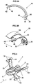
- the segments 10 are made in one piece by injection molding from plastic and have an approximately sector-like shape. How closer Figure 3B 5, the segments 10 are subdivided into a first calotte area 12 and a second calotte area 14 in the longitudinal direction L.
- the first calotte area 12 has approximately the shape of the sector of a ball ring whose ball center point in the closed state (FIG. 1A ) substantially coincides with the center of the joint ball 5 of the inner part 3.
- the second dome region 14 has a midpoint displaced in the longitudinal direction L and a larger radius of curvature so that it can receive and cover a corresponding first dome region 12 of the adjacent link 2.
- the dome areas 12, 14 thus achieve the desired overlap ( 1A ), without affecting the flexibility of the members 2.
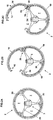
- each of three webs 20 of the inner part 3 and each of the segments 10 each have a hinge assembly 30 is provided by means of which the segments 10 are movably mounted on the inner part 3 and can be swung outwardly ( 2B-2C ).
- the segments 10 are movably mounted on the inner part 3 and can be swung outwardly ( 2B-2C ).
- the access takes place peripherally or over the circumference of the shell or of the shell part 4, by being able to be accessed essentially radially in the guide duct 7 belonging to the respective shell part 4.
- the joint assembly 30 between each segment 10 and each web 20 offers in the illustrated embodiment, two degrees of freedom, namely a rotational movement about an axis perpendicular to the plane of the 2A-2C and an adjustment or sliding movement of the segment 10 along a curve within this plane, transverse to the longitudinal direction L.
- the hinge assembly 30 is such that the segment 10 can be pivoted when pivoting with its inner end quasi radially outward on an adjacent segment 10 out.
- the pivoting of the closed shell parts 4 is made possible and also prevents squeezing and jamming of the overlapping dome areas 12, 14, such as Figure 2c shows closer.
- Each hinge assembly 30 is disposed in the closed state on the inside of the corresponding segment 10 and is thus largely protected by the shell part 4.
- Each hinge assembly 30 according to 2A-2C corresponds to a combination of a rotary joint and a cam guide or a sliding guide with a rotatable engagement member at a flat view. This arrangement is how a comparison of FIG.3B and FIG.4 2 shows, realized with two circumferentially protruding, claw-shaped hinge brackets 32, which are integrally formed on one end of the segment 10, and with correspondingly formed as a bearing pin hinge portions 34 at the end region of each web 20.
- the hinge portions 34 are substantially parallel to the longitudinal direction L or ., Guiding direction of the wiring 1 pin-like manner and are formed here by an approximately circular cylindrical cross bolt on the web 20.
- the claw-shaped hinge bracket 32 surround the hinge portions 34 rotatably on the webs.
- the two hinge bracket 32 are designed identically and arranged in parallel in the longitudinal direction L in alignment.
- the hinge brackets 32 each form a slot-like guide 33 for the hinge bracket 32.
- the slot-like guide 33 is substantially in the circumferential direction directed the shell part and thus provides the curve movement of the rotary and cam guide 30, for example, according to a circumferentially or tangentially directed straight line or slightly curved curve.
- the axis of rotation of the hinge bracket 32 about the hinge portions 34 is approximately parallel to the longitudinal direction L directed, the direction of curvature of the guide 33 is exactly or nearly perpendicular thereto (in the plane of 3a ).
- a constriction 35 is provided, which cooperates with the hinge portions 34.
- the hinge portions 34 engage in the two opposite end positions in the guide 33 a. This allows the segments 10 in the open position according to 1B being held.
- the joint regions 34 are each freely rotatable, in order to allow an up and Schwenkwenken.
- the guide 33 in the hinge bracket 32 allows that the segment 10 is held on the hinge portions 34 and yet in the region of the overlap in the longitudinal direction L over an adjacent segment 10 can be pivoted away.
- the axis of rotation defined by the hinge portions 34 is within the enclosure, as shown in FIG Figure 2c a segment 10 in each case over the circumference and the longitudinal direction L adjacent segment 10 are pivoted.
- the dome region 14 of the one segment 10 can be opened outwardly beyond the dome region 12 of the longitudinal direction L of the segment.
- an opening 36 is also directed outward, which serves to remove the segment 10 from the web 20.
- the openings 36 are located in the end region of the guide 33, which surrounds the peg-shaped joint regions 34 in the pivoted-up end position. So only in this position ( 1B ) the segment 10 are easily removed.
- the segments 10 are made of an elastically deformable plastic, possibly made of softer material than the internal parts. 3
- 3A-3B further show a formed on the swiveling end of the segment 10 locking projection 40 with a latching hook 42nd Wie 1A shows, the locking projection 40 engages in the free space between the two hinge bracket 32 of the circumferentially closest segment 10 and is designed so that it almost completely closes this space.
- the latching hook 42 is latched to a latching edge 44, which is provided approximately centrally on the web 10, more precisely on the cylindrical portions forming the hinge areas 34.
- the latching projection 40 claw-like surrounds the central region on the web 20 between the hinge portions 34, whereby the segments 10 are held stably on the webs 20 in the manner of a positive clamping or clip connection.
- two extensions 45 are formed in the longitudinal direction L on the segment 10, which are designed as a cover of the openings 36, and close this almost completely with closed shell parts 4.
- Out 1B shows that the joint arrangement 30 is provided exclusively in the longitudinal area between the first dome area 12 of the segments 10 and the web 10 so that the overlapping of the dome areas 12, 14 on the one hand and the size of the joint arrangement 30 in the longitudinal direction 30 on the other hand can be as large as possible, like out 1A-1B seen.
- FIG.4 shows the inner part 3 of a member 2 with three in the arc angle of 120 ° rotationally symmetrical integrally formed struts or spoke-like webs 20 which extend from the central part with the hinge connectors 5, 6 radially outward.
- Each web 20 serves as a holder for exactly one corresponding segment 10 and delimits with this segment 10 and the closest in the circumferential direction web 20 one of three guide channels 7 of the wiring 1 from.
- the webs 20 are not only radially outward, but each curved with a component in the longitudinal direction L.
- the effective length in the longitudinal direction L of the hinge portions 34 against tilting of the segments 10 substantially over the entire corresponding dimension of the first Dome area 12 extend.
- the three segments 10 of the shell part 4 are identically shaped. How out 1B As can be seen, the segments 10 are designed so that with closed segments 10, the shell parts 4 adjacent members 2 with the cap areas 12, 14 (here only the straight arrangement shown) fully overlap except for remaining construction-related columns. Due to the spherical shape and sufficient overlap in the longitudinal direction L, form the shell parts 4 in all Abwinklungs einen a closed enclosure around the guide channels 7 and the lines therein (not shown).
Landscapes
- Engineering & Computer Science (AREA)
- General Engineering & Computer Science (AREA)
- Mechanical Engineering (AREA)
- Architecture (AREA)
- Civil Engineering (AREA)
- Structural Engineering (AREA)
- Details Of Indoor Wiring (AREA)
- Electric Cable Arrangement Between Relatively Moving Parts (AREA)
Claims (15)
- Guide-câble (1) comportant des maillons (2) respectivement ajustables en angle multiaxialement l'un par rapport à l'autre, reliés l'un à l'autre de manière articulée et disposés successivement dans un sens longitudinal (L) du guide-câble (1), chaque maillon (2) présentant une partie intérieure (3), avec des connecteurs d'articulation (5, 6) ajustables en angle, et une partie de gaine (4) pour la délimitation périphérique d'au moins un conduit de guidage (7), la partie de gaine (4) comprenant au moins un segment (10) qui est relié, de manière pivotante pour rendre accessible un conduit de guidage associé (7) du côté périphérique, à la partie intérieure (3) par une âme (20) caractérisé
en ce que
les parties de gaine (4) de maillons (2) adjacents se chevauchent dans la direction longitudinale (L), et
en ce qu'un agencement d'articulation (30) avec au moins deux degrés de liberté est prévu entre le au moins un segment (10) et l'âme (20), au moyen duquel le segment (10) peut se déplacer transversalement par rapport à la direction longitudinale (L), en particulier vers l'extérieur, lorsqu'il est pivoté en ouverture. - Guide-câble selon la revendication 1, caractérisé en ce que l'agencement d'articulation (30) est situé à l'intérieur par rapport à la partie de gaine (4).
- Guide-câble selon la revendication 1 ou 2, caractérisé en ce que l'agencement d'articulation (30) est réalisé sous forme d'une combinaison de deux articulations, en particulier sous forme d'un guide rotatif et cintré avec une direction de courbure transversale à l'axe de rotation, l'axe de rotation étant de préférence orienté sensiblement parallèlement à la direction longitudinale (L).
- Guide-câble selon la revendication 3, caractérisé en ce que deux pattes d'articulation (32) en forme de griffes s'appuient sur une extrémité du au moins un segment (10), formant un guide (33) à trou oblong pour le mouvement de courbure du guide rotatif et cintré, et s'engageant en rotation autour de zones d'articulation (34) correspondantes qui sont conçues comme des tourillons et font saillie sur l'âme (20).
- Guide-câble selon la revendication 4, caractérisé en ce que le guide (33) à trou oblong s'étend essentiellement dans la direction périphérique de la partie de gaine et présente de préférence un étranglement (35) entre les deux zones d'extrémité du guide pour le verrouillage en deux positions finales.
- Guide-câble selon l'une des revendications 1 à 5, caractérisé
en ce que sur l'extrémité du segment (10) opposée à l'agencement d'articulation (30) est prévue une saillie d'encliquetage (40), de préférence avec un crochet d'encliquetage (30), engageant l'âme la plus proche dans le sens périphérique, de préférence sur un bord d'encliquetage (44) sur l'âme. - Guide-câble selon la revendication 6, caractérisé en ce que la saillie d'encliquetage (40) pénètre dans un interstice entre les deux pattes d'articulation (32) du segment le plus proche dans le sens périphérique.
- Guide-câble selon l'une quelconque des revendications précédentes, notamment selon la revendication 7, caractérisé
en ce que l'agencement d'articulation (30), en particulier chaque pattes d'articulation (32), présente au moins une ouverture (36) orientée vers l'extérieur pour détacher le segment (10) de l'âme (20), et en ce que au moins une saillie (45) est prévue sur l'extrémité du segment opposée à l'ensemble d'articulation (30) pour recouvrir l'ouverture du segment le plus proche dans le sens périphérique. - Guide-câble selon la revendication 8, caractérisé en ce que l'ouverture (36) est prévue dans une zone d'extrémité correspondant à la position finale ouverte de l'agencement d'articulation (30).
- Guide-câble selon l'une quelconque des revendications précédentes, caractérisé en ce que chaque segment (10) est divisé en deux zones de calotte sphérique (12, 14) dans la direction longitudinale, la première zone de calotte (12) présentant un point central de la sphère qui coïncide essentiellement avec le centre d'un élément d'articulation (5) du type à rotule sur la partie intérieure (3), et la deuxième zone de calotte (14) pouvant au moins partiellement recevoir la première zone de calotte (12) du maillon (2) adjacent, et en ce que l'agencement d'articulation (30), en particulier le rotatif et cintré, est prévu seulement entre la première zone de calotte (12) et l'âme (20).
- Guide-câble selon la revendication 10, caractérisé en ce que la partie de gaine (4) de chaque maillon (2) présente plusieurs segments (10) identiques, en particulier trois segments (10), fabriqués d'une seule pièce, et plusieurs âmes (20), en particulier trois âmes (20), sont moulés d'une seule pièce sur la partie intérieure (3), de manière symétrique en révolution, en particulier sur la section longitudinale médiane de la pièce intérieure (3).
- Guide-câble selon la revendication 11, caractérisé en ce que les âmes (20) s'étendent radialement vers l'extérieur et avec un composant dans la direction longitudinale (L).
- Guide-câble selon la revendication 11 ou 12, caractérisé en ce que des parties de l'agencement d'articulation (30), en particulier des zones d'articulation (34) conçues comme des tourillons, sont moulées d'une seul pièce sur l'extrémité extérieure de chaque âme (10), leur longueur effective s'étendant essentiellement sur toute la dimension dans la direction longitudinale (L) de la première zone de calotte (12).
- Guide-câble selon l'une quelconque des revendications précédentes, caractérisé en ce que la partie de gaine (4) est constituée de plusieurs segments (10) identiques, de préférence trois, chaque segment (10) étant de préférence fabriqué d'une seule pièce (10), et chaque segment (10) étant pivotant et conçu de telle sorte que, lorsque les segments (10) sont fermés, les parties de gaine (4) des maillons (2) adjacents s'étendent l'une sur l'autre dans toutes les positions angulaires et essentiellement sur leur périphérie entière.
- Guide-câble selon l'une quelconque des revendications précédentes, caractérisé en ce que la partie intérieure (3) de chaque maillon (2) présente des connecteurs d'articulation (5, 6) correspondants du type cardan ou à rotule qui sont conçus pour une connexion ajustable en angle multiaxialement et pour l'absorption de forces de traction.
Priority Applications (2)
| Application Number | Priority Date | Filing Date | Title |
|---|---|---|---|
| PL16201514T PL3159987T3 (pl) | 2013-04-05 | 2014-03-24 | Prowadnica przewodów ze zginanymi względem siebie wieloosiowo członami |
| EP16201514.3A EP3159987B1 (fr) | 2013-04-05 | 2014-03-24 | Dispositif de passage de câbles constitué d'éléments pouvant se dérouler selon plusieurs axes |
Applications Claiming Priority (2)
| Application Number | Priority Date | Filing Date | Title |
|---|---|---|---|
| DE202013101460U DE202013101460U1 (de) | 2013-04-05 | 2013-04-05 | Leitungsführung aus mehrachsig abwinkelbaren Gliedern |
| PCT/EP2014/055798 WO2014161734A1 (fr) | 2013-04-05 | 2014-03-24 | Dispositif de passage de câbles constitué d'éléments pliables selon plusieurs axes |
Related Child Applications (2)
| Application Number | Title | Priority Date | Filing Date |
|---|---|---|---|
| EP16201514.3A Division EP3159987B1 (fr) | 2013-04-05 | 2014-03-24 | Dispositif de passage de câbles constitué d'éléments pouvant se dérouler selon plusieurs axes |
| EP16201514.3A Division-Into EP3159987B1 (fr) | 2013-04-05 | 2014-03-24 | Dispositif de passage de câbles constitué d'éléments pouvant se dérouler selon plusieurs axes |
Publications (2)
| Publication Number | Publication Date |
|---|---|
| EP2982015A1 EP2982015A1 (fr) | 2016-02-10 |
| EP2982015B1 true EP2982015B1 (fr) | 2017-02-15 |
Family
ID=48465367
Family Applications (2)
| Application Number | Title | Priority Date | Filing Date |
|---|---|---|---|
| EP16201514.3A Active EP3159987B1 (fr) | 2013-04-05 | 2014-03-24 | Dispositif de passage de câbles constitué d'éléments pouvant se dérouler selon plusieurs axes |
| EP14712288.1A Active EP2982015B1 (fr) | 2013-04-05 | 2014-03-24 | Dispositif de passage de câbles constitué d'éléments pliables selon plusieurs axes |
Family Applications Before (1)
| Application Number | Title | Priority Date | Filing Date |
|---|---|---|---|
| EP16201514.3A Active EP3159987B1 (fr) | 2013-04-05 | 2014-03-24 | Dispositif de passage de câbles constitué d'éléments pouvant se dérouler selon plusieurs axes |
Country Status (12)
| Country | Link |
|---|---|
| US (1) | US9435464B2 (fr) |
| EP (2) | EP3159987B1 (fr) |
| JP (2) | JP6415534B2 (fr) |
| KR (1) | KR102284885B1 (fr) |
| CN (1) | CN105144514B (fr) |
| BR (1) | BR112015025012B1 (fr) |
| CA (1) | CA2908377C (fr) |
| DE (1) | DE202013101460U1 (fr) |
| ES (2) | ES2624962T3 (fr) |
| PL (2) | PL2982015T3 (fr) |
| TW (1) | TWI546472B (fr) |
| WO (1) | WO2014161734A1 (fr) |
Families Citing this family (39)
| Publication number | Priority date | Publication date | Assignee | Title |
|---|---|---|---|---|
| DE102014107232B4 (de) | 2014-05-22 | 2024-11-21 | Tsubaki Kabelschlepp GmbH | Räumlich auslenkbare Leitungsführungseinrichtung |
| DE102015200665A1 (de) * | 2015-01-16 | 2016-07-21 | Deckel Maho Pfronten Gmbh | Bearbeitungseinheit für eine Werkzeugmaschine und eine derartige Werkzeugmaschine |
| CN105370989A (zh) * | 2015-11-24 | 2016-03-02 | 重庆市龙山金属材料有限公司 | 一种可弯曲圆管 |
| US10128643B2 (en) * | 2016-10-13 | 2018-11-13 | Illinois Tool Works Inc. | Loom assembly providing improved electrical isolation |
| DE202017102310U1 (de) | 2017-04-19 | 2017-08-11 | Igus Gmbh | Magazinvorrichtung für Leitungen und Leitungsführungseinrichtungen |
| EP3402026B1 (fr) * | 2017-05-11 | 2020-07-08 | HellermannTyton GmbH | Ensemble constitué de modules de canal de câble assemblés |
| JP6739105B2 (ja) | 2017-11-06 | 2020-08-12 | 株式会社国盛化学 | ケーブル保護装置 |
| US10962345B2 (en) | 2018-05-23 | 2021-03-30 | General Electric Company | Tool and method for inspecting an annular space of an engine |
| DE202018103418U1 (de) * | 2018-06-18 | 2018-12-19 | Igus Gmbh | Leitungsführungseinrichtung für hängende Anwendungen, insbesondere als Service-Loop für eine Bohranlage |
| US11707819B2 (en) | 2018-10-15 | 2023-07-25 | General Electric Company | Selectively flexible extension tool |
| US12194620B2 (en) | 2018-10-15 | 2025-01-14 | Oliver Crisipin Robotics Limited | Selectively flexible extension tool |
| US11702955B2 (en) | 2019-01-14 | 2023-07-18 | General Electric Company | Component repair system and method |
| EP3689560A1 (fr) * | 2019-01-31 | 2020-08-05 | Bic Violex S.A. | Tête de rasage à intervalle inter-lame accru |
| PL3917730T3 (pl) | 2019-01-31 | 2024-11-04 | BIC Violex Single Member S.A. | Wkład golarki |
| EP3981052B1 (fr) * | 2019-06-05 | 2026-04-15 | Tyco Fire Products LP | Connecteur serrant |
| CN110233464B (zh) * | 2019-06-18 | 2022-10-04 | 北京金风科创风电设备有限公司 | 进线装置及海上风力发电机组 |
| DE202019105125U1 (de) | 2019-09-16 | 2020-10-21 | Igus Gmbh | Drehführung für eine oder mehrere Leitungen |
| US12405187B2 (en) | 2019-10-04 | 2025-09-02 | General Electric Company | Insertion apparatus for use with rotary machines |
| CN110815291B (zh) * | 2019-11-19 | 2024-05-24 | 福莱斯伯(安徽)精密科技有限公司 | 一种外圆扣接式可拆卸机器人电缆套管 |
| DE102019133971A1 (de) * | 2019-12-11 | 2021-06-17 | Alfred Kärcher SE & Co. KG | Vorrichtung zum führen einer flexiblen leitung |
| KR102129124B1 (ko) * | 2019-12-24 | 2020-07-02 | (주)효원엔지니어링 | 광케이블 포설 및 간격유지장치 |
| US11752622B2 (en) | 2020-01-23 | 2023-09-12 | General Electric Company | Extension tool having a plurality of links |
| US11692650B2 (en) | 2020-01-23 | 2023-07-04 | General Electric Company | Selectively flexible extension tool |
| US11613003B2 (en) | 2020-01-24 | 2023-03-28 | General Electric Company | Line assembly for an extension tool having a plurality of links |
| US11371437B2 (en) * | 2020-03-10 | 2022-06-28 | Oliver Crispin Robotics Limited | Insertion tool |
| GB2595207A (en) * | 2020-05-04 | 2021-11-24 | Stirling Moulded Composites Ltd | Long article management conduit and method for producing the same |
| CN111577986A (zh) * | 2020-05-18 | 2020-08-25 | 钟建斌 | 一种进气歧管的安装支架 |
| US12091981B2 (en) | 2020-06-11 | 2024-09-17 | General Electric Company | Insertion tool and method |
| DE202020104482U1 (de) * | 2020-08-03 | 2021-09-06 | Igus Gmbh | Leitungsführungseinrichtung für hängende Anwendungen, insbesondere Bohranlagen, Bohrgeräte oder dgl. |
| CN112260174A (zh) * | 2020-10-31 | 2021-01-22 | 江苏科瑞斯机件有限公司 | 快速拆装穿线导链 |
| DE202020106401U1 (de) * | 2020-11-06 | 2021-12-07 | Igus Gmbh | Ausgabevorrichtung für eine flexible Leitungsanordnung und Leitungsführungseinrichtung mit Fördereinheit |
| US11977217B2 (en) | 2020-12-04 | 2024-05-07 | General Electric Company | Insertion tool |
| US12416800B2 (en) | 2021-01-08 | 2025-09-16 | General Electric Company | Insertion tool |
| US12504616B2 (en) | 2021-01-08 | 2025-12-23 | General Electric Company | Insertion tool |
| US11654547B2 (en) | 2021-03-31 | 2023-05-23 | General Electric Company | Extension tool |
| CN113175576A (zh) * | 2021-04-26 | 2021-07-27 | 南京磁谷科技股份有限公司 | 一种磁悬浮空压机自调节恒温排气分水器 |
| CN115621966B (zh) * | 2021-07-16 | 2024-07-05 | 黄俊杰 | 一种可调节的电缆接头 |
| IT202200012158A1 (it) * | 2022-06-08 | 2023-12-08 | Prysmian Spa | Gruppo di giunzione per cavi elettrici aventi un cavo di fibra ottica integrato in differenti posizioni radiali, sistema di giunzione e metodo per installare tale gruppo di giunzione. |
| DE202023106221U1 (de) | 2023-10-27 | 2025-01-30 | Igus Gmbh | Drehmodul zur Führung mindestens einer Leitung und Drehmodul mit mindestens einer Leitung |
Family Cites Families (14)
| Publication number | Priority date | Publication date | Assignee | Title |
|---|---|---|---|---|
| EP0038952B1 (fr) * | 1980-04-30 | 1984-05-16 | Kabelschlepp Gesellschaft mit beschränkter Haftung | Support pour lignes d'énergie |
| MY125832A (en) * | 1995-11-06 | 2006-08-30 | Japan Recom Ltd | Closure for cable connection |
| DE19948926B4 (de) | 1998-12-15 | 2009-06-04 | Kabelschlepp Gmbh | Kettenglied einer Energieführungskette |
| JP2003135381A (ja) | 2001-10-31 | 2003-05-13 | Machida Endscope Co Ltd | 湾曲管及びその製造方法 |
| JP3349148B1 (ja) | 2001-12-11 | 2002-11-20 | 株式会社椿本チエイン | 密閉型ケーブルドラグチェーン |
| DE10216081B4 (de) * | 2002-04-11 | 2005-03-31 | Kabelschlepp Gmbh | Roboter mit einer Leitungsführungseinrichtung |
| DE20305679U1 (de) * | 2003-04-07 | 2003-06-18 | Igus Spritzgußteile für die Industrie GmbH, 51147 Köln | Kabelführung |
| JP4376822B2 (ja) | 2005-04-22 | 2009-12-02 | 川崎重工業株式会社 | 変形構造体およびケーブルの支持装置 |
| DE202009005546U1 (de) | 2009-04-16 | 2009-06-18 | Igus Gmbh | Kabelführung |
| DE102010032920C5 (de) | 2010-07-30 | 2023-03-02 | Tsubaki Kabelschlepp GmbH | Räumlich auslenkbare Leitungsführungseinrichtung mit Krümmungsradiusbegrenzern |
| DE102010037751A1 (de) | 2010-09-22 | 2012-03-22 | Sven Keßler | Halbschalenelement |
| JP5618933B2 (ja) * | 2011-07-25 | 2014-11-05 | 株式会社椿本チエイン | ケーブル類保護案内装置 |
| DE202012001760U1 (de) | 2012-02-23 | 2012-05-30 | Igus Gmbh | Kabelführung |
| JP5414820B2 (ja) * | 2012-02-27 | 2014-02-12 | 株式会社椿本チエイン | ケーブル類保護案内装置 |
-
2013
- 2013-04-05 DE DE202013101460U patent/DE202013101460U1/de not_active Expired - Lifetime
-
2014
- 2014-03-24 BR BR112015025012-2A patent/BR112015025012B1/pt active IP Right Grant
- 2014-03-24 WO PCT/EP2014/055798 patent/WO2014161734A1/fr not_active Ceased
- 2014-03-24 CA CA2908377A patent/CA2908377C/fr active Active
- 2014-03-24 US US14/782,425 patent/US9435464B2/en active Active
- 2014-03-24 ES ES14712288.1T patent/ES2624962T3/es active Active
- 2014-03-24 JP JP2016505754A patent/JP6415534B2/ja active Active
- 2014-03-24 EP EP16201514.3A patent/EP3159987B1/fr active Active
- 2014-03-24 PL PL14712288T patent/PL2982015T3/pl unknown
- 2014-03-24 CN CN201480019739.5A patent/CN105144514B/zh active Active
- 2014-03-24 KR KR1020157031737A patent/KR102284885B1/ko active Active
- 2014-03-24 ES ES16201514.3T patent/ES2687425T3/es active Active
- 2014-03-24 EP EP14712288.1A patent/EP2982015B1/fr active Active
- 2014-03-24 PL PL16201514T patent/PL3159987T3/pl unknown
- 2014-04-03 TW TW103112403A patent/TWI546472B/zh active
-
2018
- 2018-10-02 JP JP2018187198A patent/JP6846394B2/ja active Active
Also Published As
| Publication number | Publication date |
|---|---|
| CA2908377A1 (fr) | 2014-10-09 |
| BR112015025012A2 (pt) | 2017-07-18 |
| EP3159987B1 (fr) | 2018-06-13 |
| PL3159987T3 (pl) | 2019-01-31 |
| CN105144514A (zh) | 2015-12-09 |
| JP6415534B2 (ja) | 2018-10-31 |
| WO2014161734A1 (fr) | 2014-10-09 |
| JP2016515796A (ja) | 2016-05-30 |
| EP2982015A1 (fr) | 2016-02-10 |
| CA2908377C (fr) | 2021-05-04 |
| PL2982015T3 (pl) | 2017-09-29 |
| TWI546472B (zh) | 2016-08-21 |
| ES2624962T3 (es) | 2017-07-18 |
| US20160040803A1 (en) | 2016-02-11 |
| BR112015025012B1 (pt) | 2021-02-23 |
| KR102284885B1 (ko) | 2021-08-02 |
| KR20150139587A (ko) | 2015-12-11 |
| EP3159987A1 (fr) | 2017-04-26 |
| JP2019037126A (ja) | 2019-03-07 |
| TW201502396A (zh) | 2015-01-16 |
| ES2687425T3 (es) | 2018-10-25 |
| US9435464B2 (en) | 2016-09-06 |
| DE202013101460U1 (de) | 2013-04-22 |
| JP6846394B2 (ja) | 2021-03-24 |
| CN105144514B (zh) | 2017-08-04 |
Similar Documents
| Publication | Publication Date | Title |
|---|---|---|
| EP2982015B1 (fr) | Dispositif de passage de câbles constitué d'éléments pliables selon plusieurs axes | |
| DE10216081B4 (de) | Roboter mit einer Leitungsführungseinrichtung | |
| DE4334523B4 (de) | Schnappbefestigung, Gehörschutzvorrichtung und störungsgeschützter Kopfsprechhörer | |
| DE60111702T2 (de) | Kabelführungskette | |
| EP1200753B1 (fr) | Chaine articulee pour cables d'alimentation | |
| DE102012219881B4 (de) | Endoskopisches Instrument | |
| DE10050565C2 (de) | Kabelbaum-Abwinkelvorrichtung | |
| EP3122520A1 (fr) | Bras de robot et kit de montage | |
| EP2861879A1 (fr) | Palier lisse pour un arbre de direction | |
| EP3245023B1 (fr) | Unité d'usinage destinée à une machine-outil et machine-outil de ce type | |
| EP3123056B1 (fr) | Dispositif de protection destiné à un pare-chocs | |
| DE1775585A1 (de) | Kettenanordnung zur Lagerung biegsamer Leitungen | |
| EP3020107B1 (fr) | Système de fixation et/ou de guidage d'éléments en forme de boudins | |
| EP3784439A1 (fr) | Pince | |
| DE102018116011B4 (de) | Dichtungsmittel, Basisanordnung mit einem solchen Dichtungsmittel und Rückblickvorrichtung mit einer solchen Basisanordnung | |
| EP3723928B1 (fr) | Dispositif de coupe pour couper des tubes ondulés à longueur et guidage des saillies dans un tel dispositif de coupe | |
| EP1398552A1 (fr) | Support pivotant pour un tuyau | |
| DE202013101992U1 (de) | Leitungsführung mit mehrachsig abwinkelbaren Gliedern | |
| EP4297940B1 (fr) | Dispositif de guidage de ligne pouvant être dévié dans l'espace, en particulier pour un robot | |
| DE10141407A1 (de) | Vorrichtung zum Halten eines Leitungsbündels bei einem Roboter | |
| EP1308076A1 (fr) | Arrangement protecteur en particulier pour joint à cardan double | |
| DE20305487U1 (de) | Kabelführung | |
| EP1400740B1 (fr) | Dispositif de fixation d'un tuyau flexible | |
| DE202017105244U1 (de) | Energieführungskette mit in die Gelenkverbindungen integrierten Schwenkwinkel-Anschlägen und entsprechende Kettenlaschen | |
| DE2357908A1 (de) | Gliederkette |
Legal Events
| Date | Code | Title | Description |
|---|---|---|---|
| PUAI | Public reference made under article 153(3) epc to a published international application that has entered the european phase |
Free format text: ORIGINAL CODE: 0009012 |
|
| 17P | Request for examination filed |
Effective date: 20151029 |
|
| AK | Designated contracting states |
Kind code of ref document: A1 Designated state(s): AL AT BE BG CH CY CZ DE DK EE ES FI FR GB GR HR HU IE IS IT LI LT LU LV MC MK MT NL NO PL PT RO RS SE SI SK SM TR |
|
| AX | Request for extension of the european patent |
Extension state: BA ME |
|
| DAX | Request for extension of the european patent (deleted) | ||
| GRAP | Despatch of communication of intention to grant a patent |
Free format text: ORIGINAL CODE: EPIDOSNIGR1 |
|
| INTG | Intention to grant announced |
Effective date: 20160824 |
|
| GRAS | Grant fee paid |
Free format text: ORIGINAL CODE: EPIDOSNIGR3 |
|
| GRAA | (expected) grant |
Free format text: ORIGINAL CODE: 0009210 |
|
| AK | Designated contracting states |
Kind code of ref document: B1 Designated state(s): AL AT BE BG CH CY CZ DE DK EE ES FI FR GB GR HR HU IE IS IT LI LT LU LV MC MK MT NL NO PL PT RO RS SE SI SK SM TR |
|
| REG | Reference to a national code |
Ref country code: CH Ref legal event code: EP Ref country code: GB Ref legal event code: FG4D Free format text: NOT ENGLISH |
|
| REG | Reference to a national code |
Ref country code: IE Ref legal event code: FG4D Free format text: LANGUAGE OF EP DOCUMENT: GERMAN |
|
| REG | Reference to a national code |
Ref country code: AT Ref legal event code: REF Ref document number: 868381 Country of ref document: AT Kind code of ref document: T Effective date: 20170315 |
|
| REG | Reference to a national code |
Ref country code: DE Ref legal event code: R096 Ref document number: 502014002713 Country of ref document: DE Ref country code: FR Ref legal event code: PLFP Year of fee payment: 4 |
|
| REG | Reference to a national code |
Ref country code: CH Ref legal event code: NV Representative=s name: KATZAROV S.A., CH |
|
| REG | Reference to a national code |
Ref country code: NL Ref legal event code: MP Effective date: 20170215 |
|
| REG | Reference to a national code |
Ref country code: LT Ref legal event code: MG4D |
|
| REG | Reference to a national code |
Ref country code: ES Ref legal event code: FG2A Ref document number: 2624962 Country of ref document: ES Kind code of ref document: T3 Effective date: 20170718 |
|
| PG25 | Lapsed in a contracting state [announced via postgrant information from national office to epo] |
Ref country code: HR Free format text: LAPSE BECAUSE OF FAILURE TO SUBMIT A TRANSLATION OF THE DESCRIPTION OR TO PAY THE FEE WITHIN THE PRESCRIBED TIME-LIMIT Effective date: 20170215 Ref country code: NO Free format text: LAPSE BECAUSE OF FAILURE TO SUBMIT A TRANSLATION OF THE DESCRIPTION OR TO PAY THE FEE WITHIN THE PRESCRIBED TIME-LIMIT Effective date: 20170515 Ref country code: FI Free format text: LAPSE BECAUSE OF FAILURE TO SUBMIT A TRANSLATION OF THE DESCRIPTION OR TO PAY THE FEE WITHIN THE PRESCRIBED TIME-LIMIT Effective date: 20170215 Ref country code: LT Free format text: LAPSE BECAUSE OF FAILURE TO SUBMIT A TRANSLATION OF THE DESCRIPTION OR TO PAY THE FEE WITHIN THE PRESCRIBED TIME-LIMIT Effective date: 20170215 Ref country code: GR Free format text: LAPSE BECAUSE OF FAILURE TO SUBMIT A TRANSLATION OF THE DESCRIPTION OR TO PAY THE FEE WITHIN THE PRESCRIBED TIME-LIMIT Effective date: 20170516 |
|
| PG25 | Lapsed in a contracting state [announced via postgrant information from national office to epo] |
Ref country code: SE Free format text: LAPSE BECAUSE OF FAILURE TO SUBMIT A TRANSLATION OF THE DESCRIPTION OR TO PAY THE FEE WITHIN THE PRESCRIBED TIME-LIMIT Effective date: 20170215 Ref country code: BG Free format text: LAPSE BECAUSE OF FAILURE TO SUBMIT A TRANSLATION OF THE DESCRIPTION OR TO PAY THE FEE WITHIN THE PRESCRIBED TIME-LIMIT Effective date: 20170515 Ref country code: RS Free format text: LAPSE BECAUSE OF FAILURE TO SUBMIT A TRANSLATION OF THE DESCRIPTION OR TO PAY THE FEE WITHIN THE PRESCRIBED TIME-LIMIT Effective date: 20170215 Ref country code: LV Free format text: LAPSE BECAUSE OF FAILURE TO SUBMIT A TRANSLATION OF THE DESCRIPTION OR TO PAY THE FEE WITHIN THE PRESCRIBED TIME-LIMIT Effective date: 20170215 Ref country code: NL Free format text: LAPSE BECAUSE OF NON-PAYMENT OF DUE FEES Effective date: 20170215 Ref country code: PT Free format text: LAPSE BECAUSE OF FAILURE TO SUBMIT A TRANSLATION OF THE DESCRIPTION OR TO PAY THE FEE WITHIN THE PRESCRIBED TIME-LIMIT Effective date: 20170615 |
|
| PG25 | Lapsed in a contracting state [announced via postgrant information from national office to epo] |
Ref country code: RO Free format text: LAPSE BECAUSE OF FAILURE TO SUBMIT A TRANSLATION OF THE DESCRIPTION OR TO PAY THE FEE WITHIN THE PRESCRIBED TIME-LIMIT Effective date: 20170215 Ref country code: EE Free format text: LAPSE BECAUSE OF FAILURE TO SUBMIT A TRANSLATION OF THE DESCRIPTION OR TO PAY THE FEE WITHIN THE PRESCRIBED TIME-LIMIT Effective date: 20170215 Ref country code: SK Free format text: LAPSE BECAUSE OF FAILURE TO SUBMIT A TRANSLATION OF THE DESCRIPTION OR TO PAY THE FEE WITHIN THE PRESCRIBED TIME-LIMIT Effective date: 20170215 |
|
| REG | Reference to a national code |
Ref country code: DE Ref legal event code: R097 Ref document number: 502014002713 Country of ref document: DE |
|
| PG25 | Lapsed in a contracting state [announced via postgrant information from national office to epo] |
Ref country code: SM Free format text: LAPSE BECAUSE OF FAILURE TO SUBMIT A TRANSLATION OF THE DESCRIPTION OR TO PAY THE FEE WITHIN THE PRESCRIBED TIME-LIMIT Effective date: 20170215 Ref country code: MC Free format text: LAPSE BECAUSE OF FAILURE TO SUBMIT A TRANSLATION OF THE DESCRIPTION OR TO PAY THE FEE WITHIN THE PRESCRIBED TIME-LIMIT Effective date: 20170215 Ref country code: DK Free format text: LAPSE BECAUSE OF FAILURE TO SUBMIT A TRANSLATION OF THE DESCRIPTION OR TO PAY THE FEE WITHIN THE PRESCRIBED TIME-LIMIT Effective date: 20170215 |
|
| PLBE | No opposition filed within time limit |
Free format text: ORIGINAL CODE: 0009261 |
|
| STAA | Information on the status of an ep patent application or granted ep patent |
Free format text: STATUS: NO OPPOSITION FILED WITHIN TIME LIMIT |
|
| REG | Reference to a national code |
Ref country code: IE Ref legal event code: MM4A |
|
| 26N | No opposition filed |
Effective date: 20171116 |
|
| PG25 | Lapsed in a contracting state [announced via postgrant information from national office to epo] |
Ref country code: LU Free format text: LAPSE BECAUSE OF NON-PAYMENT OF DUE FEES Effective date: 20170324 |
|
| PG25 | Lapsed in a contracting state [announced via postgrant information from national office to epo] |
Ref country code: SI Free format text: LAPSE BECAUSE OF FAILURE TO SUBMIT A TRANSLATION OF THE DESCRIPTION OR TO PAY THE FEE WITHIN THE PRESCRIBED TIME-LIMIT Effective date: 20170215 Ref country code: IE Free format text: LAPSE BECAUSE OF NON-PAYMENT OF DUE FEES Effective date: 20170324 |
|
| REG | Reference to a national code |
Ref country code: CH Ref legal event code: PCAR Free format text: NEW ADDRESS: AVENUE DES MORGINES 12, 1213 PETIT-LANCY (CH) |
|
| REG | Reference to a national code |
Ref country code: FR Ref legal event code: PLFP Year of fee payment: 5 |
|
| PG25 | Lapsed in a contracting state [announced via postgrant information from national office to epo] |
Ref country code: MT Free format text: LAPSE BECAUSE OF FAILURE TO SUBMIT A TRANSLATION OF THE DESCRIPTION OR TO PAY THE FEE WITHIN THE PRESCRIBED TIME-LIMIT Effective date: 20170215 |
|
| PGFP | Annual fee paid to national office [announced via postgrant information from national office to epo] |
Ref country code: PL Payment date: 20190319 Year of fee payment: 6 Ref country code: CZ Payment date: 20190321 Year of fee payment: 6 Ref country code: GB Payment date: 20190325 Year of fee payment: 6 Ref country code: FR Payment date: 20190326 Year of fee payment: 6 Ref country code: CH Payment date: 20190325 Year of fee payment: 6 |
|
| PGFP | Annual fee paid to national office [announced via postgrant information from national office to epo] |
Ref country code: BE Payment date: 20190321 Year of fee payment: 6 Ref country code: AT Payment date: 20190319 Year of fee payment: 6 |
|
| PG25 | Lapsed in a contracting state [announced via postgrant information from national office to epo] |
Ref country code: HU Free format text: LAPSE BECAUSE OF FAILURE TO SUBMIT A TRANSLATION OF THE DESCRIPTION OR TO PAY THE FEE WITHIN THE PRESCRIBED TIME-LIMIT; INVALID AB INITIO Effective date: 20140324 |
|
| PG25 | Lapsed in a contracting state [announced via postgrant information from national office to epo] |
Ref country code: CY Free format text: LAPSE BECAUSE OF FAILURE TO SUBMIT A TRANSLATION OF THE DESCRIPTION OR TO PAY THE FEE WITHIN THE PRESCRIBED TIME-LIMIT Effective date: 20170215 |
|
| PG25 | Lapsed in a contracting state [announced via postgrant information from national office to epo] |
Ref country code: MK Free format text: LAPSE BECAUSE OF FAILURE TO SUBMIT A TRANSLATION OF THE DESCRIPTION OR TO PAY THE FEE WITHIN THE PRESCRIBED TIME-LIMIT Effective date: 20170215 |
|
| PG25 | Lapsed in a contracting state [announced via postgrant information from national office to epo] |
Ref country code: TR Free format text: LAPSE BECAUSE OF FAILURE TO SUBMIT A TRANSLATION OF THE DESCRIPTION OR TO PAY THE FEE WITHIN THE PRESCRIBED TIME-LIMIT Effective date: 20170215 |
|
| PG25 | Lapsed in a contracting state [announced via postgrant information from national office to epo] |
Ref country code: AL Free format text: LAPSE BECAUSE OF FAILURE TO SUBMIT A TRANSLATION OF THE DESCRIPTION OR TO PAY THE FEE WITHIN THE PRESCRIBED TIME-LIMIT Effective date: 20170215 Ref country code: IS Free format text: LAPSE BECAUSE OF FAILURE TO SUBMIT A TRANSLATION OF THE DESCRIPTION OR TO PAY THE FEE WITHIN THE PRESCRIBED TIME-LIMIT Effective date: 20170615 |
|
| PG25 | Lapsed in a contracting state [announced via postgrant information from national office to epo] |
Ref country code: CZ Free format text: LAPSE BECAUSE OF NON-PAYMENT OF DUE FEES Effective date: 20200324 |
|
| REG | Reference to a national code |
Ref country code: CH Ref legal event code: PL |
|
| REG | Reference to a national code |
Ref country code: AT Ref legal event code: MM01 Ref document number: 868381 Country of ref document: AT Kind code of ref document: T Effective date: 20200324 |
|
| REG | Reference to a national code |
Ref country code: BE Ref legal event code: MM Effective date: 20200331 |
|
| PG25 | Lapsed in a contracting state [announced via postgrant information from national office to epo] |
Ref country code: FR Free format text: LAPSE BECAUSE OF NON-PAYMENT OF DUE FEES Effective date: 20200331 Ref country code: AT Free format text: LAPSE BECAUSE OF NON-PAYMENT OF DUE FEES Effective date: 20200324 Ref country code: LI Free format text: LAPSE BECAUSE OF NON-PAYMENT OF DUE FEES Effective date: 20200331 Ref country code: CH Free format text: LAPSE BECAUSE OF NON-PAYMENT OF DUE FEES Effective date: 20200331 |
|
| PG25 | Lapsed in a contracting state [announced via postgrant information from national office to epo] |
Ref country code: BE Free format text: LAPSE BECAUSE OF NON-PAYMENT OF DUE FEES Effective date: 20200331 |
|
| GBPC | Gb: european patent ceased through non-payment of renewal fee |
Effective date: 20200324 |
|
| PG25 | Lapsed in a contracting state [announced via postgrant information from national office to epo] |
Ref country code: GB Free format text: LAPSE BECAUSE OF NON-PAYMENT OF DUE FEES Effective date: 20200324 |
|
| REG | Reference to a national code |
Ref country code: ES Ref legal event code: FD2A Effective date: 20210812 |
|
| PG25 | Lapsed in a contracting state [announced via postgrant information from national office to epo] |
Ref country code: ES Free format text: LAPSE BECAUSE OF NON-PAYMENT OF DUE FEES Effective date: 20200325 |
|
| PG25 | Lapsed in a contracting state [announced via postgrant information from national office to epo] |
Ref country code: PL Free format text: LAPSE BECAUSE OF NON-PAYMENT OF DUE FEES Effective date: 20200324 |
|
| P01 | Opt-out of the competence of the unified patent court (upc) registered |
Effective date: 20230526 |
|
| PGFP | Annual fee paid to national office [announced via postgrant information from national office to epo] |
Ref country code: DE Payment date: 20250527 Year of fee payment: 12 |
|
| PGFP | Annual fee paid to national office [announced via postgrant information from national office to epo] |
Ref country code: IT Payment date: 20250331 Year of fee payment: 12 |
|
| REG | Reference to a national code |
Ref country code: DE Ref legal event code: R081 Ref document number: 502014002713 Country of ref document: DE Owner name: IGUS SE & CO. KG, DE Free format text: FORMER OWNER: IGUS GMBH, 51147 KOELN, DE |