EP2982302B1 - Applicateur médical - Google Patents
Applicateur médical Download PDFInfo
- Publication number
- EP2982302B1 EP2982302B1 EP14179911.4A EP14179911A EP2982302B1 EP 2982302 B1 EP2982302 B1 EP 2982302B1 EP 14179911 A EP14179911 A EP 14179911A EP 2982302 B1 EP2982302 B1 EP 2982302B1
- Authority
- EP
- European Patent Office
- Prior art keywords
- medical applicator
- veterinarian
- human
- cavity
- insertion needle
- Prior art date
- Legal status (The legal status is an assumption and is not a legal conclusion. Google has not performed a legal analysis and makes no representation as to the accuracy of the status listed.)
- Not-in-force
Links
Images


Classifications
-
- A—HUMAN NECESSITIES
- A61—MEDICAL OR VETERINARY SCIENCE; HYGIENE
- A61B—DIAGNOSIS; SURGERY; IDENTIFICATION
- A61B17/00—Surgical instruments, devices or methods
- A61B17/34—Trocars; Puncturing needles
- A61B17/3468—Trocars; Puncturing needles for implanting or removing devices, e.g. prostheses, implants, seeds, wires
-
- A—HUMAN NECESSITIES
- A61—MEDICAL OR VETERINARY SCIENCE; HYGIENE
- A61B—DIAGNOSIS; SURGERY; IDENTIFICATION
- A61B17/00—Surgical instruments, devices or methods
- A61B17/34—Trocars; Puncturing needles
-
- A—HUMAN NECESSITIES
- A61—MEDICAL OR VETERINARY SCIENCE; HYGIENE
- A61B—DIAGNOSIS; SURGERY; IDENTIFICATION
- A61B5/00—Measuring for diagnostic purposes; Identification of persons
- A61B5/145—Measuring characteristics of blood in vivo, e.g. gas concentration or pH-value ; Measuring characteristics of body fluids or tissues, e.g. interstitial fluid or cerebral tissue
- A61B5/14503—Measuring characteristics of blood in vivo, e.g. gas concentration or pH-value ; Measuring characteristics of body fluids or tissues, e.g. interstitial fluid or cerebral tissue invasive, e.g. introduced into the body by a catheter or needle or using implanted sensors
-
- A—HUMAN NECESSITIES
- A61—MEDICAL OR VETERINARY SCIENCE; HYGIENE
- A61B—DIAGNOSIS; SURGERY; IDENTIFICATION
- A61B5/00—Measuring for diagnostic purposes; Identification of persons
- A61B5/145—Measuring characteristics of blood in vivo, e.g. gas concentration or pH-value ; Measuring characteristics of body fluids or tissues, e.g. interstitial fluid or cerebral tissue
- A61B5/14532—Measuring characteristics of blood in vivo, e.g. gas concentration or pH-value ; Measuring characteristics of body fluids or tissues, e.g. interstitial fluid or cerebral tissue for measuring glucose, e.g. by tissue impedance measurement
-
- A—HUMAN NECESSITIES
- A61—MEDICAL OR VETERINARY SCIENCE; HYGIENE
- A61B—DIAGNOSIS; SURGERY; IDENTIFICATION
- A61B5/00—Measuring for diagnostic purposes; Identification of persons
- A61B5/68—Arrangements of detecting, measuring or recording means, e.g. sensors, in relation to patient
- A61B5/6801—Arrangements of detecting, measuring or recording means, e.g. sensors, in relation to patient specially adapted to be attached to or worn on the body surface
- A61B5/683—Means for maintaining contact with the body
- A61B5/6832—Means for maintaining contact with the body using adhesives
-
- A—HUMAN NECESSITIES
- A61—MEDICAL OR VETERINARY SCIENCE; HYGIENE
- A61B—DIAGNOSIS; SURGERY; IDENTIFICATION
- A61B5/00—Measuring for diagnostic purposes; Identification of persons
- A61B5/68—Arrangements of detecting, measuring or recording means, e.g. sensors, in relation to patient
- A61B5/6801—Arrangements of detecting, measuring or recording means, e.g. sensors, in relation to patient specially adapted to be attached to or worn on the body surface
- A61B5/683—Means for maintaining contact with the body
- A61B5/6832—Means for maintaining contact with the body using adhesives
- A61B5/68335—Means for maintaining contact with the body using adhesives including release sheets or liners
-
- A—HUMAN NECESSITIES
- A61—MEDICAL OR VETERINARY SCIENCE; HYGIENE
- A61B—DIAGNOSIS; SURGERY; IDENTIFICATION
- A61B17/00—Surgical instruments, devices or methods
- A61B17/30—Surgical pincettes, i.e. surgical tweezers without pivotal connections
- A61B2017/306—Surgical pincettes, i.e. surgical tweezers without pivotal connections holding by means of suction
- A61B2017/308—Surgical pincettes, i.e. surgical tweezers without pivotal connections holding by means of suction with suction cups
-
- A—HUMAN NECESSITIES
- A61—MEDICAL OR VETERINARY SCIENCE; HYGIENE
- A61B—DIAGNOSIS; SURGERY; IDENTIFICATION
- A61B2217/00—General characteristics of surgical instruments
- A61B2217/002—Auxiliary appliance
- A61B2217/005—Auxiliary appliance with suction drainage system
-
- A—HUMAN NECESSITIES
- A61—MEDICAL OR VETERINARY SCIENCE; HYGIENE
- A61B—DIAGNOSIS; SURGERY; IDENTIFICATION
- A61B2503/00—Evaluating a particular growth phase or type of persons or animals
- A61B2503/40—Animals
-
- A—HUMAN NECESSITIES
- A61—MEDICAL OR VETERINARY SCIENCE; HYGIENE
- A61B—DIAGNOSIS; SURGERY; IDENTIFICATION
- A61B2560/00—Constructional details of operational features of apparatus; Accessories for medical measuring apparatus
- A61B2560/04—Constructional details of apparatus
- A61B2560/0443—Modular apparatus
- A61B2560/045—Modular apparatus with a separable interface unit, e.g. for communication
-
- A—HUMAN NECESSITIES
- A61—MEDICAL OR VETERINARY SCIENCE; HYGIENE
- A61B—DIAGNOSIS; SURGERY; IDENTIFICATION
- A61B2560/00—Constructional details of operational features of apparatus; Accessories for medical measuring apparatus
- A61B2560/06—Accessories for medical measuring apparatus
- A61B2560/063—Devices specially adapted for delivering implantable medical measuring apparatus
-
- A—HUMAN NECESSITIES
- A61—MEDICAL OR VETERINARY SCIENCE; HYGIENE
- A61B—DIAGNOSIS; SURGERY; IDENTIFICATION
- A61B2562/00—Details of sensors; Constructional details of sensor housings or probes; Accessories for sensors
- A61B2562/24—Hygienic packaging for medical sensors; Maintaining apparatus for sensor hygiene
- A61B2562/242—Packaging, i.e. for packaging the sensor or apparatus before use
Definitions
- the invention relates to an apparatus for insertion of a medical sensor or probe for in vivo monitoring of an analyte in a human or veterinarian body and in particular to a medical applicator for inserting a transcutaneous analyte sensor into a subcutaneous region of a human or veterinarian body.
- analyte levels in the blood stream or interstitial fluid of a subject.
- the patient routinely monitors the glucose levels to avoid hypoglycemic episodes and hyperglycemic episodes.
- other analytes such as lactate or oxygen, may be measured.
- an electrochemical sensor may be inserted into a subcutaneous tissue region of the subject where the analyte concentration is continuously monitored and/or logged.
- publication US 2008/0242962 A1 discloses a monitoring system for monitoring analyte concentration, such as glucose, with an implantable sensor.
- the implantable sensor is configured to generate measurement signals which are compressed through statistical techniques to produce compressed measurement data that may be easier to process and communicate.
- a base station carries the implantable sensor along with a signal processor, a memory, and a transmitter.
- a display device is also disclosed that can receive the compressed measurement data from the base station for further processing and display.
- publication US 8,515,519 B2 discloses a transcutaneous analyte sensor assembly to be mounted on a skin of a host with a first side of the housing.
- the housing further comprises a sensor electronics unit having one or more electrical contacts, wherein the sensor electronics unit is configured to releasable mate with a second side of the housing opposite to the first side such that the one or more electrical contacts of the housing electrically connect with the one or more electrical contacts of the sensor electronics unit.
- the sensor is configured to continuously and/or intermittently measure a level of an analyte in a tissue of the host.
- the sensor further comprises one or more electrical contact points configured to electrically connect to the electrical contacts of the sensor electronics unit via the electrical contacts of the housing when the sensor electronics unit is mated to the housing. Additionally, the housing is configured to continuously support the sensor within the tissue of the host during a time period of continuous or intermittent measurement.
- publication WO 2008/39944 A2 discloses devices and methods for positioning a portion of a sensor at a first predetermined location, displacing the portion of the sensor from the first predetermined location to a second predetermined location, and detecting one or signals associated with an analyte level of a patient at the second predetermined location are disclosed.
- publication WO 96/25088 A1 discloses an insertion set for transcutaneous placement of a sensor such as a glucose sensor at a selected site within the body of a patient.
- the insertion set comprises a slotted insertion needle extending through a mounting base adapted for mounting onto the patient's skin.
- a flexible thin film sensor includes a proximal segment carried by the mounting base and defining conductive contacts, unnumbered, adapted for electrical connection to a suitable monitor, and a distal segment protruding from the mounting base with sensor electrodes for transcutaneous placement.
- the distal segment of the sensor extends within a protective cannula, a portion of which is slidably disposed within the insertion needle. Placement of the mounting base onto the patient's skin causes the insertion needle to pierce the skin for transcutaneous placement of the cannula with the sensor therein.
- US 2010/0016786 A1 discloses methods and devices for forming tracts in tissue.
- the devices comprise an elongate member, a suction member coupled to a distal portion of the elongate member, and a tissue-piercing member slidably housed within the elongate member for forming a tract in tissue.
- publication EP 2 668 901 A1 discloses a sensor insertion assembly including a sensor cartridge.
- the sensor cartridge comprises an insertion needle and a sensor within a sterile capsule.
- the sensor insertion assembly further comprises an inserter having a chamber for receiving the sensor cartridge, wherein the inserter further comprises an insertion mechanism operable for actuating the insertion needle for inserting the sensor into a subject.
- the sensor cartridge is removable from the chamber.
- the sensor cartridge is operable for shielding the insertion needle upon removal of the sensor cartridge from the chamber.
- the invention provides for a medical applicator for insertion of a sensor assembly into a human or veterinarian body, a manipulation unit and a medical application system according to the independent claims.
- a medical applicator for insertion of a sensor assembly into a human or veterinarian body, a manipulation unit and a medical application system according to the independent claims.
- Various embodiments and enhancements thereto are given in the respective dependent claims.
- a principal medical applicator comprises an insertion needle being configured for puncturing a part of a human or veterinarian body, a sensor assembly being configured to be at least partially inserted into the human or veterinarian body when being punctured by the insertion needle, and lifting means for lifting up a surface adjacent portion of the human or veterinarian body towards the insertion needle so that the sensor assembly is at least partially inserted into the human or veterinarian body.
- the medical applicator has lifting means comprising a container member defining a cavity and an orifice, the cavity being configured for receiving the sensor assembly, the insertion needle being located within the cavity at a recessed position relative to the orifice and being configured for puncturing a part of the human or veterinarian body entering through the orifice, the lifting means further comprising means for applying underpressure to the cavity for taking, through the orifice, an adjacent portion of the human or veterinarian body into the cavity by suction.
- the sensor assembly of the medical applicator comprises an external device being configured to remain outside the human or veterinarian body after deployment of the sensor assembly.
- the external device has at least one self-adhesive surface portion facing towards the orifice.
- This may advantageously allow an operation wherein the soft skin and subcutaneous tissue is displaced away from the underlying muscular tissue for puncturing and thereby may help in avoiding injury thereof.
- Suction based operation may have the advantage of equilibrated and widely-spread force application and may help avoiding hematoma and unintentional injury of skin and/or subcutaneous tissue.
- the means for applying underpressure to the cavity comprise a suction port formed in an exterior wall of the container member.
- the suction port is defined by a predetermined braking point in an exterior wall of the container member.
- the cavity of the medical applicator has the shape of a dome or ventouse.
- the medical applicator is configured to allow displacement of the insertion needle relative to the orifice towards the adjacent portion of the human or veterinarian body.
- This in instances, may advantageously allow performing insertion at a more moderate underpressure and thereby may help avoiding hematoma and skin irritation.
- the container member of the medical applicator comprises a deformable section connecting the orifice to the mount of the insertion needle for allowing displacement of the insertion needle relative to the orifice by application of a deformation force to the container member.
- the deformable section may be provided in the shape of a bellow and, in particular, in the shape of a flat and/or cylindrical bellow.
- the medical applicator has the insertion needle being slidably movable relative to the container member.
- the insertion needle is supported by a piston member, whereby the piston member being slidably movable within a section of the container member and being exposable to an actuating force by means of a biased elastic member and/or by application of the underpressure.
- the external device is admittable to the application force by means of the biased elastic member and/or by application of the underpressure for deployment of the external device to the surface of the human or veterinarian body.
- the external device is releasable fixed in a biased pre-deployment position.
- the fixation of the external device is releasable by deformation of a portion of the container member and/or by retraction of retention pins.
- the medical applicator includes a sealing member extending over the orifice to cover the cavity.
- the cavity of the medical applicator contains a protective atmosphere to avoid degradation of the self-adhesive surface portion.
- the sealing member comprises a protective liner adapted for protecting the self-adhesive surface portion of the external device.
- the lifting means include pincer arms configured for creating an upwardly bending movement of the skin and subcutaneous tissue of the human or veterinarian body towards the insertion needle.
- a principal manipulation unit for facilitating utilization of a medical applicator comprises a fitting for engagement with the medical applicator and means for generation of the underpressure and/or means for applying a force to the container member of the medical applicator received in the fitting for effecting deformation thereof.
- the means for generation of underpressure comprises an electric vacuum pump.
- the fitting of the manipulation unit is configured as a suction holder.
- the manipulation unit further comprises puncturing means for puncturing the container member of the medical applicator received in the fitting to form the suction port for the application of the underpressure.
- the manipulation unit additionally comprises progress sensor means for detecting the presence of a portion of the human or veterinarian body at an internal location within the cavity of the medical applicator and generating a signal descriptive thereto.
- the progress sensor means of the manipulation unit comprises an optical detection device, especially an infrared radiation or image sensor device.
- the manipulation unit has an electronic controller configured for operating the vacuum pump in response to the signal of the progress sensor means.
- a principal medical application system comprises a medical applicator and a manipulation unit.
- the medical applicator is inserted into the fitting of the manipulation unit and the means for generation of the underpressure is connected with the means for applying underpressure of the medical applicator.
- a first exemplary configuration of a medical applicator may have a container member 102.
- the container member 102 may define a cavity 104 and an orifice 106.
- the container member 102 may be dome shaped, as shown.
- the cavity 104 may, for example, be configured to receive a sensor assembly and, in particular, a transcutaneous analyte sensor assembly 110 to be applied to a human or veterinarian body B.
- an insertion needle 108 may be provided at a fixed mount located inside the cavity 104.
- the container member 102 may be made from a thermoplastic resin whereby the insertion needle may be moulded into a mount portion.
- the insertion needle 108 may have the tip located at a recessed position behind the orifice 106. Additionally, the insertion needle 108 may be aligned to project from the interior of the cavity 104 towards the orifice 106.
- the insertion needle 108 may have a longitudinal groove for receiving a sensor wire, a probe tube or the like.
- the insertion needle 108 may be a grooved needle or hollow needle with a cross-section that has been removed.
- the insertion needle 108 may have a C-shape or V-shape cross-section. This may enable the insertion needle 108 to partially insert the transcutaneous analyte sensor assembly 110 and then remove the needle while leaving the sensor within the human or veterinarian body.
- the diameter of the insertion needle 108 has been considerably exaggerated throughout all schematic drawings.
- the transcutaneous analyte sensor assembly 110 may be located within the cavity 104 at an internal position distant from the orifice 106.
- the transcutaneous analyte sensor assembly 110 may include an external device 112 configured to remain outside the human or veterinarian body B after application, preferably in contact to the skin surface.
- the external device 112 may have a flat bottom surface coated with an adhesive for fixation.
- the transcutaneous analyte sensor assembly 110 may have a probe portion to be at least partially inserted into the subcutaneous tissue of human or veterinarian body B via a channel through the skin.
- the probe portion may include an electrical sensor 114 at a distal position and a wiring for providing connection to the external device 112.
- an electrical sensor 114 at a distal position and a wiring for providing connection to the external device 112.
- the external device 112 of the sensor assembly 110 may comprise a through hole or slot for adjustment and/or fixation on the insertion needle 108.
- the through hole or slot may be designed for slightly frictional clamping or engagement with the insertion needle 108, as shown.
- the frictional clamping force may be chosen such as to allow the external device 112 to be pulled away from the insertion needle 108 by effect of an adhesive force applicable to the underside of the external device 112 when fixed by adhesion to the skin of a human or veterinarian body.
- mechanical and/or adhesive means for fixation of the external device 112 to the skin of a human or veterinarian body might be provided inside the cavity 104.
- a sealing member 116 may be provided to tightly extend over the orifice 106 as a closure to the cavity 104.
- the closure may help to avoid contamination of the transcutaneous analyte sensor assembly 110 and the insertion needle 108 during stock and transport of the medical applicator 100.
- the sealing member 116 may be equipped with an additional protective liner 118 which is configured to prevent the adhesive on bottom surface of the external device 112 from degradation during stock and transport.
- the protective liner 118 may be a flexible strip extending over the adhesive and having an end portion connected to an inner portion of the sealing member 116, as shown. In such situation, removal of the sealing member 116 will cause the flexible strip to be peeled from the adhesive in a single action.
- the adhesive on the bottom surface of the external device 112 might be protected by means of a protective gas charge contained in the cavity 104. Then, there would be no need for additional protective coverage.
- the sealing member 116 might be provided in a configuration of a rigid sealing cap.
- the sealing cap might be provided in a configuration of twist-off sealing cap to facilitate unlocking and removal from the container member 102.
- the sealing cap might be provided with a central stiff portion protruding into the cavity 104 and having a flat portion covering the adhesive on bottom surface of the external device 112.
- the stiff portion of the sealing cap might be configured to serve as a protection sleeve for the insertion needle 108.
- the container member 102 may have a suction port 120 formed in an exterior wall thereof.
- the suction port 120 may be used for applying vacuum or underpressure to the cavity 104 to effect at least partial evacuation thereof.
- the suction port 120 may be provided with a removable closure or coverage to avoid contamination of the cavity 104 and/or insertion needle 108 through this passage to the exterior.
- the removable closure of the suction port 120 may have the form of an integrally made stitch-through membrane portion or diaphragm in the exterior wall 120. There may be provided a section having reduced thickness in the exterior wall, as shown. This may allow the suction port 120 to be easily formed by punching this section with a lancet or an edged suction nozzle of an evacuation pump or vacuum device.
- the suction port might be formed initially as a through hole in the container member 102. In such situation, another closure member might be provided as a cover to the suction port for avoiding contamination of the cavity 104 and/or insertion needle 108 via the suction port 120.
- the medical applicator 100 may be positioned onto the skin of a human or veterinarian body B in a position wherein the orifice 106 having tightly annular contact to the skin surface.
- the suction port 120 of the container member 102 may be opened as described before.
- vacuum or underpressure may be applied to the cavity 104 for at least partial evacuation thereof.
- Annular contact between orifice 106 and skin surface will prevent cavity 104 from being vented through orifice 106.
- pressure in cavity 104 decreases, the skin and underlying subcutaneous tissue of the human or veterinarian body B adjacent to orifice 106 will become pushed into cavity 104 by outer pressure.
- the applicator 100 as a whole will be pressed onto the human or veterinarian body B due to outer pressure.
- Continued evacuation of the cavity 104 may throw up a limited surface adjacent portion of the human or veterinarian body (B) against the insertion needle 108. This may be used to bring the skin into contact with the insertion needle 108 and, subsequently, to perform puncturing of the skin and subcutaneous tissue of the human or veterinarian body B by the insertion needle 108. Further decrease in cavity pressure then may cause the skin surface to lie against the bottom surface of the external device 112.
- the adhesive provided on the bottom surface of the external device 112 as explained before may cause fixation of the external device 112 to the skin surface of the human or veterinarian body B.
- the cavity 104 may be vented via the suction port 120. Then, the skin and/or subcutaneous tissue formerly drawn into cavity 104 by suction may relax into its initial shape by internal elasticity. If, as explained before, adhesive bonding has been established between the skin and the external device 112 this may cause the transcutaneous analyte sensor assembly 110 to be extracted from the cavity 104 of the applicator 100 in course of venting.
- the empty container member 102 of the medical applicator 100 may be removed from the human or veterinarian body B. For avoidance of unintentional removal, the transcutaneous analyte sensor assembly 110 may be covered by a plaster or similar well-known protection. Finally, the empty container member 102 of the medical applicator 100 may be disposed or collected for remanufacturing.
- the manipulation unit 200 may have a casing 202 equipped with a fitting 204 configured to receive a medical applicator 100. Further, there may be a battery 206 operated electrical vacuum pump 208 arranged in the casing 202 of the manipulation unit 200.
- the vacuum pump 208 may be connected to a port 210 inside the fitting 204.
- the port 210 may be located to match with the position of the suction port 120 of a medical applicator 100 when correctly inserted into the fitting 204.
- the vacuum pump 208 may include means for opening the suction port 120 of the medical applicator 100 before evacuation.
- the suction port 120 of the medical applicator 100 may be opened by perforation of a thin-walled portion of the container member 102 as explained before.
- the manipulation unit 200 may comprise a perforation means as a punch or lancet, for example.
- the manipulation unit 200 may have a sealing gasket 212 configured to surround the container member 102 of the medical applicator 100 when correctly inserted into the fitting 204.
- the sealing gasket 212 may serve to prevent external air to bypass into the fitting 204 thereby causing loss or degradation of vacuum generated by vacuum pump 208 via port 210.
- the manipulation unit 200 may additionally comprise means for enabling at least semi-automatically operation.
- There may be an electronic controller 214 included in the casing 202.
- the electronic controller 214 may be battery 206 operated and configured to control operation of the vacuum pump 208.
- progress sensor means 216 may be configured inside the fitting 204 to provide the electronic controller 214 with a signal significant for a certain stage of operation.
- the progress sensor means 216 may include, for example, a sensor configured for detection of the skin of a human or veterinarian body B entering into the cavity 104 of the medical applicator 100 received in the fitting 204.
- the progress sensor means 216 may include an optical sensor as, for example, a photoelectrical barrier or the like.
- the electronic controller 214 may be configured to terminate operation of the vacuum pump 208 in response to receiving a signal from the progress sensor means 216.
- the electronic controller 214 may be configured to switch the vacuum pump 208 to a reverse operation mode afterwards for venting the cavity 104 of the medical applicator 100 received in the fitting 204.
- the electronic controller 214 may be configured to stop reverse operation of the vacuum pump 208 after a predetermined time period has lapsed.
- the electronic controller 214 may provide the user of the manipulation unit 200 with a signal upon termination of operation as an indication to remove the empty container member 102 of the medical applicator 100 from the fitting 204.
- this signal may be vibrational, optical and/or visual.
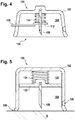
- a spring 124 or any other kind of elastic member may be provided for biasing the external device 112 of the transcutaneous analyte sensor assembly 110 in a direction outwardly respective to cavity 104.
- Biasing force may advantageously be used to improve deployment of the external device 112. Additionally, such biasing force may advantageously increase the contact pressure between the bottom surface of the external device 112 and the skin surface of the human or veterinarian body B thereby strengthening a potential adhesive fixation, if present.
- Releasable fixation means may be provided for securing of the external device 112 in a pre-deployment position.
- the releasable fixation means may be implemented as a number of retractable retention pins 128.
- the retention pins may extend through an outer wall of the container member 102 into the cavity 104 thereby allowing actuation from outside the cavity 104, as shown.
- retraction may be performed manually, preferably at a certain stage during deployment of the sensor device 110.
- a user may retract the retention pins 128 before venting the cavity 104 to thereby enable the external device to 112 follow the relaxation of the portion of the human or veterinarian body.
- the releasable fixation means may be implemented as retractable fixation clips inside the cavity 104.
- the fixation clips may be formed integrally with the container member 102.
- the container member 102 may be configured to release the fixation clips when being subject to a deformation.
- the required deformation of the container member 102 may be effected as a result of the pressure difference in course of a deployment operation as explained before with reference to Fig. 2 .
- the container member 102 may have an approximate ellipsoidal shape in a cross-section perpendicular to the insertion needle 108 at the height of the clips whereby the semi-major axis may lie in the plane of the drawing sheet.
- lowering the pressure inside the cavity 104 may cause the container member 102 to flatten along the semi-minor axis. Flattening in one direction, however, may cause the container member 102 to stretch along the semi-major axis at the same time. This may be used for driving the fixation clips away from each other thereby unengaging from the external device 112. As a result, the external device 112 may be released from the fixation clips. A biasing force may push the external device 112 towards the orifice 106 afterwards.
- the stiffness of the container member 102 may be designed to perform releasing of the fixation clips at the end of evacuation.
- a third improvement may be given by means to enable relative displacement of the insertion needle 108 respective to the container member 102 or, more particularly, to the orifice 106 during a deployment operation.
- the insertion needle 108 may be mounted on a piston or slider 122.
- the container member 102 may be configured to allow displacement of the piston or slider 122 to a certain extent. Typically, displacement will be limited to a direction approximately parallel to the insertion needle's 108 longitudinal dimension.
- the container member 102 may have a cylindrical guidance section to restrict movement of the piston or slider 122 to a linear travel, as shown.
- the piston 122 may be gas-tightly received in the guidance section. This will enable gas pressure driven displacement during deployment operation.
- the piston 122 may be configured to separate a predetermined gas volume 126 from the cavity 104. This separated gas volume 126 may act as an elastic member thereby causing the piston 122 to displace towards the orifice 106 during evacuation of the cavity 104 via the suction port 120.
- displacement of the piston 122 may cause the insertion needle 108 to be driven towards punctuation of the human or veterinarian body B adjacent to the orifice 106. This may advantageously result in faster deployment operation and may additionally allow performing punctuation at a lower pressure difference.
- a spring 124 or any similar elastically structural member may be provided to replace and/or support the effect of the gas pressure difference as described before.
- it may be considered as an obvious advantage of a mainly gas pressure difference driven displacement of the insertion needle 108 to depend on tight closure of the orifice 106.
- an unintentional application of vacuum or underpressure to the medical applicator 100 without a tight contact to a human or veterinarian body B will not cause the insertion needle 108 to be pushed towards the orifice 106.
- this may be used as an inherent security feature.
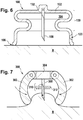
- a fourth exemplary embodiment of a medical applicator 100 may have the container member 102 provided with an elastic section as, for example a flat and/or cylindrical bellow.
- the cylindrical bellow may be formed in a cylindrical section between the needle mount 132 and the orifice 106.
- the number of beadings in the bellow has been reduced to two, namely a positive, outwardly projecting beading in the upper region which smoothly fades into a negative, inwardly projecting beading in the lower section.
- the spring rate of the bellow 130 may be adjusted to prevent it from significantly compressing until the amount of underpressure in the cavity 104 has reached a value sufficient for taking the body portion B into to the required extent.
- a fifth exemplary embodiment of a medical applicator may include a medical applicator 300 having an insertion needle 308 and a generalized lifting means for throwing up a limited and surface adjacent portion of the human or veterinarian body B against the insertion needle 308.
- the lifting means may be realized as a number of pincer arms 302 configured to create an upwardly bending plication in the skin and subcutaneous tissue of the human or veterinarian body B when being pushed together.
- the pincer arms 302 may be pivotable relative to a base member 304 carrying the insertion needle 308.
- the pincer arms 302 may be hinge mounted to the base member 304, as shown.
- the pincer arms 302 may be manually actuated in a basic exemplary situation. Not shown in the drawing, an actuating means may be provided to enable semi-automatic or full-automatic operation of the pincer arms. An additional raising mechanism may be provided for raising the pincer arms 302 upwardly versus the insertion needle 308. It may be understood as an advantage of this approach to allow implementation for direct manual operation without necessity of additional manipulation units or similar expensive devices.
- the fifth exemplary embodiment as described before may be provided with means for supporting elastically and/or spring biased deployment operation in a manner analogous to the second exemplary embodiment of a medical applicator as described before.
- a pressure spring may be provided between the lower surface of the base member 304 and the upper surface of the external device 312 of the sensor assembly 310.
- a housing may be provided for receiving the pressure spring to prevent damage and/or contamination.
- the housing may be provided with a number of retention pins to maintain the pressure spring in a biased configuration. This configuration, as a result, would be very similar to the second exemplary embodiment as explained before.
- a housing when a housing is considered disadvantageous for some reason, there may be provided a number of retention hooks extending from the base member 304 to the external device 312 of the sensor assembly 310.
- a number of hooking points may be provided on the top surface of the external device 312 to provide for secure engagement with the hooks.
- Automatic deployment of the sensor assembly 310 may be achieved in a similar configuration by coupling the pincer arms 302 action to the retention pins or hooks, respective.
- Such automatic deployment would be useful as allowing single-handed operation of the device by a user. This may be advantageous in self-treatment situations when the sensor assembly has to be deployed to the back of the hand or the lower arm region.
Landscapes
- Health & Medical Sciences (AREA)
- Life Sciences & Earth Sciences (AREA)
- Surgery (AREA)
- Engineering & Computer Science (AREA)
- General Health & Medical Sciences (AREA)
- Physics & Mathematics (AREA)
- Biomedical Technology (AREA)
- Heart & Thoracic Surgery (AREA)
- Medical Informatics (AREA)
- Molecular Biology (AREA)
- Veterinary Medicine (AREA)
- Animal Behavior & Ethology (AREA)
- Pathology (AREA)
- Public Health (AREA)
- Biophysics (AREA)
- Nuclear Medicine, Radiotherapy & Molecular Imaging (AREA)
- Optics & Photonics (AREA)
- Emergency Medicine (AREA)
- Infusion, Injection, And Reservoir Apparatuses (AREA)
- Media Introduction/Drainage Providing Device (AREA)
Claims (15)
- Applicateur médical (100 ; 300) comprenant :- une aiguille d'insertion (108 ; 308) étant configurée pour percer une partie d'un corps humain ou d'un animal (B) ;- un ensemble capteur (110 ; 310) étant configuré pour être au moins inséré partiellement dans le corps humain ou d'un animal (B) quand il est percé par ladite aiguille d'insertion (108 ; 308) ; et- des moyens de levage (102 ; 301 ; 302) pour soulever une partie adjacente de la surface dudit corps humain ou d'un animal (B) en direction de ladite aiguille d'insertion (108 ; 308),lesdits moyens comprenant un élément formant un récipient (102) définissant une cavité (104) et un orifice (106), ladite cavité (104) étant configurée pour recevoir ledit ensemble capteur (110), ladite aiguille d'insertion (108) étant située à l'intérieur de ladite cavité (104) à un endroit en retrait par rapport à l'orifice (106) et étant configurée pour percer une partie dudit corps humain ou d'un animal (B) entrant à travers ledit orifice (106), lesdits moyens de levage comprenant en outre des moyens (120) pour appliquer une dépression à ladite cavité (104) afin de saisir, à travers ledit orifice (106), une partie adjacente dudit corps humain ou d'un animal (B) dans ladite cavité (104) par aspiration, caractérisé en ce que
ledit ensemble capteur (110) comprend un dispositif externe (112) étant configuré pour rester à l'extérieur du corps humain ou d'un animal (B) après la mise en place dudit ensemble capteur (110) et ayant au moins une partie de surface auto-adhésive faisant face audit orifice (106). - Applicateur médical (100) selon la revendication 1, ledit applicateur médical (100) étant configuré pour permettre le déplacement de ladite aiguille d'insertion (108) par rapport audit orifice (106) en direction de ladite partie adjacente dudit corps humain ou d'un animal (B).
- Applicateur médical (100) selon la revendication 1, dans lequel ladite aiguille d'insertion (108) peut se déplacer en coulissant par rapport audit élément formant un récipient (102).
- Applicateur médical (100) selon la revendication 2, dans lequel ladite aiguille d'insertion (108) est portée par un élément piston (122), ledit élément piston (122) pouvant se déplacer en coulissant à l'intérieur d'une section dudit élément formant un récipient (102) et pouvant être exposé à une force d'actionnement au moyen d'un élément élastique déformé (124) et/ou par l'application d'une dépression.
- Applicateur médical (100) selon l'une quelconque des revendications 1 à 4, dans lequel le dispositif externe (112) permet à la force d'application de s'exercer au moyen de l'élément élastique déformé (124) et/ou par l'application d'une dépression pour la mise en place du dispositif externe (112) à la surface du corps humain ou d'un animal (B).
- Applicateur médical (100) selon la revendication 4, dans lequel ledit dispositif externe (112) est fixé de manière amovible dans une position de déploiement préalable déformée.
- Applicateur médical (100) selon la revendication 5, dans lequel ladite fixation dudit dispositif externe (112) est amovible par la déformation d'une partie de l'élément formant un récipient (102) et/ou par le retrait de broches de retenue (128).
- Applicateur médical (100) selon l'une quelconque des revendications 3 à 6, dans lequel ledit applicateur médical (100) intègre un élément d'étanchéité (116) s'étendant par dessus ledit orifice (106) pour recouvrir ladite cavité (104).
- Applicateur médical (100) selon l'une quelconque des revendications 1 à 8, par lequel lesdits moyens de levage comprennent des bras en forme de pinces (302) configurés pour créer un mouvement de flexion vers le haut de la peau et du tissu sous-cutané du corps humain ou d'un animal (B) en direction de l'aiguille d'insertion (308).
- Unité de manipulation (200) pour faciliter l'utilisation d'un applicateur médical (100) selon l'une quelconque des revendications 1 à 9, ladite unité de manipulation (200) comprenant un raccord (204) destiné à servir avec ledit applicateur médical (100) et des moyens pour générer la dépression, et/ou des moyens pour appliquer une force à l'élément formant un récipient (102) de l'applicateur médical (100) réceptionné dans ledit raccord (204) afin d'effectuer une déformation de celui-ci.
- Unité de manipulation (200) selon la revendication 10, dans laquelle lesdits moyens pour la création de la dépression comprennent une pompe à vide électrique (208).
- Unité de manipulation (200) selon l'une quelconque des revendications 10 à 11, comprenant en outre des moyens de percement pour percer l'élément formant un récipient (102) de l'applicateur médical (100) réceptionné dans le raccord (204) afin de former le port d'aspiration pour l'application de la dépression.
- Unité de manipulation (200) selon l'une quelconque des revendications 10 à 12, où ladite unité de manipulation (200) comprend à titre complémentaire des moyens de capteur d'avancement (216) afin de détecter la présence d'une partie du corps humain ou d'un animal (B) à un emplacement interne dans ladite cavité (104) dudit applicateur médical (100) et générer un signal d'identification de celle-ci.
- Unité de manipulation (200) selon la revendication 10 ou 13, ladite unité de manipulation (200) ayant un dispositif de commande électronique (214) configuré pour faire fonctionner la pompe à vide (208) en réponse audit signal desdits moyens de capteur d'avancement (216).
- Système d'application médical comprenant un applicateur médical selon l'une quelconque des revendications 1 à 9 et une unité de manipulation selon l'une quelconque des revendications 10 à 14, ledit applicateur médical (100) étant inséré dans le raccord (204) de l'unité de manipulation (200) et lesdits moyens destinés à la génération de la dépression étant reliés auxdits moyens (120) pour appliquer la dépression de l'applicateur médical (100).
Priority Applications (2)
| Application Number | Priority Date | Filing Date | Title |
|---|---|---|---|
| EP14179911.4A EP2982302B1 (fr) | 2014-08-05 | 2014-08-05 | Applicateur médical |
| US14/818,650 US10405885B2 (en) | 2014-08-05 | 2015-08-05 | Medical applicator |
Applications Claiming Priority (1)
| Application Number | Priority Date | Filing Date | Title |
|---|---|---|---|
| EP14179911.4A EP2982302B1 (fr) | 2014-08-05 | 2014-08-05 | Applicateur médical |
Publications (2)
| Publication Number | Publication Date |
|---|---|
| EP2982302A1 EP2982302A1 (fr) | 2016-02-10 |
| EP2982302B1 true EP2982302B1 (fr) | 2018-05-23 |
Family
ID=51266166
Family Applications (1)
| Application Number | Title | Priority Date | Filing Date |
|---|---|---|---|
| EP14179911.4A Not-in-force EP2982302B1 (fr) | 2014-08-05 | 2014-08-05 | Applicateur médical |
Country Status (2)
| Country | Link |
|---|---|
| US (1) | US10405885B2 (fr) |
| EP (1) | EP2982302B1 (fr) |
Families Citing this family (15)
| Publication number | Priority date | Publication date | Assignee | Title |
|---|---|---|---|---|
| CN105228522B (zh) | 2013-03-14 | 2018-06-26 | 萨诺智能公司 | 用于生物监测的人体上的微传感器 |
| US10820860B2 (en) | 2013-03-14 | 2020-11-03 | One Drop Biosensor Technologies, Llc | On-body microsensor for biomonitoring |
| US10595754B2 (en) | 2014-03-13 | 2020-03-24 | Sano Intelligence, Inc. | System for monitoring body chemistry |
| CN106102578A (zh) | 2014-03-13 | 2016-11-09 | 萨诺智能公司 | 用于监控身体化学性质的系统 |
| US20170172475A1 (en) * | 2014-03-13 | 2017-06-22 | Sano Intelligence, Inc. | System for monitoring body chemistry |
| JP2018041761A (ja) * | 2016-09-05 | 2018-03-15 | 株式会社村田製作所 | チップ状電子部品 |
| EP4397236B1 (fr) | 2017-06-02 | 2026-02-25 | i-Sens, Inc. | Ensemble applicateur de capteur pour système de surveillance continue du glucose |
| KR102200136B1 (ko) * | 2018-07-31 | 2021-01-11 | 주식회사 아이센스 | 연속 혈당 측정 장치 |
| FR3087083B1 (fr) | 2018-10-09 | 2020-10-30 | Ciel Et Terre | Dispositif electronique flottant et centre de donnees comprenant un tel dispositif |
| CN110338888B (zh) * | 2019-07-18 | 2024-05-07 | 浙江荷清柔性电子技术有限公司 | 植入施加器 |
| USD1086030S1 (en) | 2021-04-21 | 2025-07-29 | One Health Biosensing Inc. | Charging station |
| USD988882S1 (en) | 2021-04-21 | 2023-06-13 | Informed Data Systems Inc. | Sensor assembly |
| USD1076079S1 (en) | 2021-04-21 | 2025-05-20 | One Health Biosensing Inc. | Applicator assembly |
| WO2025106394A1 (fr) * | 2023-11-13 | 2025-05-22 | Abbott Diabetes Care Inc. | Applicateur simplifié pour unités sur le corps |
| EP4736758A1 (fr) * | 2024-10-31 | 2026-05-06 | I-Sens, Inc. | Applicateur pour l'acquisition d'informations biométriques |
Family Cites Families (10)
| Publication number | Priority date | Publication date | Assignee | Title |
|---|---|---|---|---|
| US5586553A (en) | 1995-02-16 | 1996-12-24 | Minimed Inc. | Transcutaneous sensor insertion set |
| JP3382853B2 (ja) * | 1998-04-09 | 2003-03-04 | 松下電器産業株式会社 | 体液検査装置 |
| US6537242B1 (en) * | 2000-06-06 | 2003-03-25 | Becton, Dickinson And Company | Method and apparatus for enhancing penetration of a member for the intradermal sampling or administration of a substance |
| US9795334B2 (en) * | 2002-04-19 | 2017-10-24 | Sanofi-Aventis Deutschland Gmbh | Method and apparatus for penetrating tissue |
| US8989833B2 (en) | 2004-07-13 | 2015-03-24 | Dexcom, Inc. | Transcutaneous analyte sensor |
| US7697967B2 (en) | 2005-12-28 | 2010-04-13 | Abbott Diabetes Care Inc. | Method and apparatus for providing analyte sensor insertion |
| EP1972267A1 (fr) | 2007-03-20 | 2008-09-24 | Roche Diagnostics GmbH | Système destiné à la mesure in vivo d'une concentration en analytes |
| US8080966B2 (en) * | 2008-07-03 | 2011-12-20 | Honeywell International Inc. | Motor control architecture for simultaneously controlling multiple motors |
| US8979882B2 (en) * | 2008-07-21 | 2015-03-17 | Arstasis, Inc. | Devices, methods, and kits for forming tracts in tissue |
| EP2668901A1 (fr) | 2012-05-31 | 2013-12-04 | Roche Diagniostics GmbH | Ensemble d'insertion de capteur, cartouche de capteur et dispositif d'insertion |
-
2014
- 2014-08-05 EP EP14179911.4A patent/EP2982302B1/fr not_active Not-in-force
-
2015
- 2015-08-05 US US14/818,650 patent/US10405885B2/en not_active Expired - Fee Related
Non-Patent Citations (1)
| Title |
|---|
| None * |
Also Published As
| Publication number | Publication date |
|---|---|
| US10405885B2 (en) | 2019-09-10 |
| EP2982302A1 (fr) | 2016-02-10 |
| US20160038180A1 (en) | 2016-02-11 |
Similar Documents
| Publication | Publication Date | Title |
|---|---|---|
| US10405885B2 (en) | Medical applicator | |
| KR102113017B1 (ko) | 수조작 압력 작동식 적용 메커니즘 | |
| CN104394757B (zh) | 经皮分析物传感器、其施加器以及相关的方法 | |
| RU2372102C2 (ru) | Исполнительная система для устройства извлечения биологической жидкости и соответствующих способов | |
| CN109924952B (zh) | 一种植入工具推针结构和植入式传感器用植入工具 | |
| CN104302333B (zh) | 皮下针插入机构 | |
| CN101460207B (zh) | 包括皮肤可安装设备及其包装件的组件 | |
| US20090292184A1 (en) | Sensor Inserter Assembly | |
| CN106137214A (zh) | 一种经皮分析物传感设备及其安装方法 | |
| CN104507388A (zh) | 传感器盒和插入件 | |
| WO2023092914A1 (fr) | Système de capteur d'analyte percutané | |
| CN110664415B (zh) | 一种敷贴装置 | |
| CN216060518U (zh) | 医疗设备及医疗辅助装置 | |
| US20250375578A1 (en) | Injection analgesia system | |
| JP2007510499A (ja) | 輸液装置のカニューレ挿入装置 | |
| WO2023092912A1 (fr) | Unité de fixation de surface corporelle | |
| CN114391838B (zh) | 植入器及其使用方法 | |
| CN110548201A (zh) | 一种注射装置 | |
| KR20230071134A (ko) | 의료기기를 삽입하기 위한 삽입 기구 및 방법 | |
| TWI907645B (zh) | 插入系統及插入醫療裝置之方法 | |
| JP2005211189A (ja) | 採血装置 | |
| KR20170110279A (ko) | 흡착부를 구비한 채혈 방법 및 장치 | |
| CN117897091A (zh) | 分析物传感器固定装置 | |
| CN113382681B (zh) | 插入装置 | |
| CN111513821B (zh) | 一种动脉留置针 |
Legal Events
| Date | Code | Title | Description |
|---|---|---|---|
| PUAI | Public reference made under article 153(3) epc to a published international application that has entered the european phase |
Free format text: ORIGINAL CODE: 0009012 |
|
| AK | Designated contracting states |
Kind code of ref document: A1 Designated state(s): AL AT BE BG CH CY CZ DE DK EE ES FI FR GB GR HR HU IE IS IT LI LT LU LV MC MK MT NL NO PL PT RO RS SE SI SK SM TR |
|
| AX | Request for extension of the european patent |
Extension state: BA ME |
|
| RAP1 | Party data changed (applicant data changed or rights of an application transferred) |
Owner name: F. HOFFMANN-LA ROCHE AG Owner name: ROCHE DIABETES CARE GMBH |
|
| 17P | Request for examination filed |
Effective date: 20160810 |
|
| RBV | Designated contracting states (corrected) |
Designated state(s): AL AT BE BG CH CY CZ DE DK EE ES FI FR GB GR HR HU IE IS IT LI LT LU LV MC MK MT NL NO PL PT RO RS SE SI SK SM TR |
|
| GRAP | Despatch of communication of intention to grant a patent |
Free format text: ORIGINAL CODE: EPIDOSNIGR1 |
|
| INTG | Intention to grant announced |
Effective date: 20171219 |
|
| GRAS | Grant fee paid |
Free format text: ORIGINAL CODE: EPIDOSNIGR3 |
|
| GRAA | (expected) grant |
Free format text: ORIGINAL CODE: 0009210 |
|
| AK | Designated contracting states |
Kind code of ref document: B1 Designated state(s): AL AT BE BG CH CY CZ DE DK EE ES FI FR GB GR HR HU IE IS IT LI LT LU LV MC MK MT NL NO PL PT RO RS SE SI SK SM TR |
|
| REG | Reference to a national code |
Ref country code: GB Ref legal event code: FG4D |
|
| REG | Reference to a national code |
Ref country code: CH Ref legal event code: EP |
|
| REG | Reference to a national code |
Ref country code: IE Ref legal event code: FG4D |
|
| REG | Reference to a national code |
Ref country code: AT Ref legal event code: REF Ref document number: 1000845 Country of ref document: AT Kind code of ref document: T Effective date: 20180615 |
|
| REG | Reference to a national code |
Ref country code: DE Ref legal event code: R096 Ref document number: 602014025782 Country of ref document: DE |
|
| REG | Reference to a national code |
Ref country code: NL Ref legal event code: MP Effective date: 20180523 |
|
| REG | Reference to a national code |
Ref country code: LT Ref legal event code: MG4D |
|
| PG25 | Lapsed in a contracting state [announced via postgrant information from national office to epo] |
Ref country code: BG Free format text: LAPSE BECAUSE OF FAILURE TO SUBMIT A TRANSLATION OF THE DESCRIPTION OR TO PAY THE FEE WITHIN THE PRESCRIBED TIME-LIMIT Effective date: 20180823 Ref country code: FI Free format text: LAPSE BECAUSE OF FAILURE TO SUBMIT A TRANSLATION OF THE DESCRIPTION OR TO PAY THE FEE WITHIN THE PRESCRIBED TIME-LIMIT Effective date: 20180523 Ref country code: NO Free format text: LAPSE BECAUSE OF FAILURE TO SUBMIT A TRANSLATION OF THE DESCRIPTION OR TO PAY THE FEE WITHIN THE PRESCRIBED TIME-LIMIT Effective date: 20180823 Ref country code: SE Free format text: LAPSE BECAUSE OF FAILURE TO SUBMIT A TRANSLATION OF THE DESCRIPTION OR TO PAY THE FEE WITHIN THE PRESCRIBED TIME-LIMIT Effective date: 20180523 Ref country code: LT Free format text: LAPSE BECAUSE OF FAILURE TO SUBMIT A TRANSLATION OF THE DESCRIPTION OR TO PAY THE FEE WITHIN THE PRESCRIBED TIME-LIMIT Effective date: 20180523 Ref country code: ES Free format text: LAPSE BECAUSE OF FAILURE TO SUBMIT A TRANSLATION OF THE DESCRIPTION OR TO PAY THE FEE WITHIN THE PRESCRIBED TIME-LIMIT Effective date: 20180523 |
|
| PG25 | Lapsed in a contracting state [announced via postgrant information from national office to epo] |
Ref country code: RS Free format text: LAPSE BECAUSE OF FAILURE TO SUBMIT A TRANSLATION OF THE DESCRIPTION OR TO PAY THE FEE WITHIN THE PRESCRIBED TIME-LIMIT Effective date: 20180523 Ref country code: HR Free format text: LAPSE BECAUSE OF FAILURE TO SUBMIT A TRANSLATION OF THE DESCRIPTION OR TO PAY THE FEE WITHIN THE PRESCRIBED TIME-LIMIT Effective date: 20180523 Ref country code: NL Free format text: LAPSE BECAUSE OF FAILURE TO SUBMIT A TRANSLATION OF THE DESCRIPTION OR TO PAY THE FEE WITHIN THE PRESCRIBED TIME-LIMIT Effective date: 20180523 Ref country code: GR Free format text: LAPSE BECAUSE OF FAILURE TO SUBMIT A TRANSLATION OF THE DESCRIPTION OR TO PAY THE FEE WITHIN THE PRESCRIBED TIME-LIMIT Effective date: 20180824 Ref country code: LV Free format text: LAPSE BECAUSE OF FAILURE TO SUBMIT A TRANSLATION OF THE DESCRIPTION OR TO PAY THE FEE WITHIN THE PRESCRIBED TIME-LIMIT Effective date: 20180523 |
|
| REG | Reference to a national code |
Ref country code: AT Ref legal event code: MK05 Ref document number: 1000845 Country of ref document: AT Kind code of ref document: T Effective date: 20180523 |
|
| PG25 | Lapsed in a contracting state [announced via postgrant information from national office to epo] |
Ref country code: SK Free format text: LAPSE BECAUSE OF FAILURE TO SUBMIT A TRANSLATION OF THE DESCRIPTION OR TO PAY THE FEE WITHIN THE PRESCRIBED TIME-LIMIT Effective date: 20180523 Ref country code: RO Free format text: LAPSE BECAUSE OF FAILURE TO SUBMIT A TRANSLATION OF THE DESCRIPTION OR TO PAY THE FEE WITHIN THE PRESCRIBED TIME-LIMIT Effective date: 20180523 Ref country code: DK Free format text: LAPSE BECAUSE OF FAILURE TO SUBMIT A TRANSLATION OF THE DESCRIPTION OR TO PAY THE FEE WITHIN THE PRESCRIBED TIME-LIMIT Effective date: 20180523 Ref country code: EE Free format text: LAPSE BECAUSE OF FAILURE TO SUBMIT A TRANSLATION OF THE DESCRIPTION OR TO PAY THE FEE WITHIN THE PRESCRIBED TIME-LIMIT Effective date: 20180523 Ref country code: AT Free format text: LAPSE BECAUSE OF FAILURE TO SUBMIT A TRANSLATION OF THE DESCRIPTION OR TO PAY THE FEE WITHIN THE PRESCRIBED TIME-LIMIT Effective date: 20180523 Ref country code: CZ Free format text: LAPSE BECAUSE OF FAILURE TO SUBMIT A TRANSLATION OF THE DESCRIPTION OR TO PAY THE FEE WITHIN THE PRESCRIBED TIME-LIMIT Effective date: 20180523 Ref country code: PL Free format text: LAPSE BECAUSE OF FAILURE TO SUBMIT A TRANSLATION OF THE DESCRIPTION OR TO PAY THE FEE WITHIN THE PRESCRIBED TIME-LIMIT Effective date: 20180523 |
|
| REG | Reference to a national code |
Ref country code: DE Ref legal event code: R097 Ref document number: 602014025782 Country of ref document: DE |
|
| PG25 | Lapsed in a contracting state [announced via postgrant information from national office to epo] |
Ref country code: SM Free format text: LAPSE BECAUSE OF FAILURE TO SUBMIT A TRANSLATION OF THE DESCRIPTION OR TO PAY THE FEE WITHIN THE PRESCRIBED TIME-LIMIT Effective date: 20180523 Ref country code: IT Free format text: LAPSE BECAUSE OF FAILURE TO SUBMIT A TRANSLATION OF THE DESCRIPTION OR TO PAY THE FEE WITHIN THE PRESCRIBED TIME-LIMIT Effective date: 20180523 |
|
| PG25 | Lapsed in a contracting state [announced via postgrant information from national office to epo] |
Ref country code: MC Free format text: LAPSE BECAUSE OF FAILURE TO SUBMIT A TRANSLATION OF THE DESCRIPTION OR TO PAY THE FEE WITHIN THE PRESCRIBED TIME-LIMIT Effective date: 20180523 |
|
| PLBE | No opposition filed within time limit |
Free format text: ORIGINAL CODE: 0009261 |
|
| REG | Reference to a national code |
Ref country code: CH Ref legal event code: PL |
|
| STAA | Information on the status of an ep patent application or granted ep patent |
Free format text: STATUS: NO OPPOSITION FILED WITHIN TIME LIMIT |
|
| GBPC | Gb: european patent ceased through non-payment of renewal fee |
Effective date: 20180823 |
|
| PG25 | Lapsed in a contracting state [announced via postgrant information from national office to epo] |
Ref country code: CH Free format text: LAPSE BECAUSE OF NON-PAYMENT OF DUE FEES Effective date: 20180831 Ref country code: LU Free format text: LAPSE BECAUSE OF NON-PAYMENT OF DUE FEES Effective date: 20180805 Ref country code: LI Free format text: LAPSE BECAUSE OF NON-PAYMENT OF DUE FEES Effective date: 20180831 |
|
| 26N | No opposition filed |
Effective date: 20190226 |
|
| REG | Reference to a national code |
Ref country code: BE Ref legal event code: MM Effective date: 20180831 |
|
| REG | Reference to a national code |
Ref country code: IE Ref legal event code: MM4A |
|
| PG25 | Lapsed in a contracting state [announced via postgrant information from national office to epo] |
Ref country code: SI Free format text: LAPSE BECAUSE OF FAILURE TO SUBMIT A TRANSLATION OF THE DESCRIPTION OR TO PAY THE FEE WITHIN THE PRESCRIBED TIME-LIMIT Effective date: 20180523 |
|
| PG25 | Lapsed in a contracting state [announced via postgrant information from national office to epo] |
Ref country code: IE Free format text: LAPSE BECAUSE OF NON-PAYMENT OF DUE FEES Effective date: 20180805 |
|
| PG25 | Lapsed in a contracting state [announced via postgrant information from national office to epo] |
Ref country code: FR Free format text: LAPSE BECAUSE OF NON-PAYMENT OF DUE FEES Effective date: 20180831 Ref country code: BE Free format text: LAPSE BECAUSE OF NON-PAYMENT OF DUE FEES Effective date: 20180831 |
|
| PG25 | Lapsed in a contracting state [announced via postgrant information from national office to epo] |
Ref country code: GB Free format text: LAPSE BECAUSE OF NON-PAYMENT OF DUE FEES Effective date: 20180823 |
|
| PG25 | Lapsed in a contracting state [announced via postgrant information from national office to epo] |
Ref country code: AL Free format text: LAPSE BECAUSE OF FAILURE TO SUBMIT A TRANSLATION OF THE DESCRIPTION OR TO PAY THE FEE WITHIN THE PRESCRIBED TIME-LIMIT Effective date: 20180523 |
|
| PG25 | Lapsed in a contracting state [announced via postgrant information from national office to epo] |
Ref country code: MT Free format text: LAPSE BECAUSE OF NON-PAYMENT OF DUE FEES Effective date: 20180805 |
|
| PG25 | Lapsed in a contracting state [announced via postgrant information from national office to epo] |
Ref country code: TR Free format text: LAPSE BECAUSE OF FAILURE TO SUBMIT A TRANSLATION OF THE DESCRIPTION OR TO PAY THE FEE WITHIN THE PRESCRIBED TIME-LIMIT Effective date: 20180523 |
|
| PG25 | Lapsed in a contracting state [announced via postgrant information from national office to epo] |
Ref country code: PT Free format text: LAPSE BECAUSE OF FAILURE TO SUBMIT A TRANSLATION OF THE DESCRIPTION OR TO PAY THE FEE WITHIN THE PRESCRIBED TIME-LIMIT Effective date: 20180523 |
|
| PG25 | Lapsed in a contracting state [announced via postgrant information from national office to epo] |
Ref country code: HU Free format text: LAPSE BECAUSE OF FAILURE TO SUBMIT A TRANSLATION OF THE DESCRIPTION OR TO PAY THE FEE WITHIN THE PRESCRIBED TIME-LIMIT; INVALID AB INITIO Effective date: 20140805 Ref country code: CY Free format text: LAPSE BECAUSE OF FAILURE TO SUBMIT A TRANSLATION OF THE DESCRIPTION OR TO PAY THE FEE WITHIN THE PRESCRIBED TIME-LIMIT Effective date: 20180523 Ref country code: MK Free format text: LAPSE BECAUSE OF NON-PAYMENT OF DUE FEES Effective date: 20180523 |
|
| PG25 | Lapsed in a contracting state [announced via postgrant information from national office to epo] |
Ref country code: IS Free format text: LAPSE BECAUSE OF FAILURE TO SUBMIT A TRANSLATION OF THE DESCRIPTION OR TO PAY THE FEE WITHIN THE PRESCRIBED TIME-LIMIT Effective date: 20180923 |
|
| PGFP | Annual fee paid to national office [announced via postgrant information from national office to epo] |
Ref country code: DE Payment date: 20210713 Year of fee payment: 8 |
|
| REG | Reference to a national code |
Ref country code: DE Ref legal event code: R119 Ref document number: 602014025782 Country of ref document: DE |
|
| PG25 | Lapsed in a contracting state [announced via postgrant information from national office to epo] |
Ref country code: DE Free format text: LAPSE BECAUSE OF NON-PAYMENT OF DUE FEES Effective date: 20230301 |