EP2983276B2 - Machine dynamoélectrique dotée d'un dispositif de surveillance d'isolation - Google Patents
Machine dynamoélectrique dotée d'un dispositif de surveillance d'isolation Download PDFInfo
- Publication number
- EP2983276B2 EP2983276B2 EP14179653.2A EP14179653A EP2983276B2 EP 2983276 B2 EP2983276 B2 EP 2983276B2 EP 14179653 A EP14179653 A EP 14179653A EP 2983276 B2 EP2983276 B2 EP 2983276B2
- Authority
- EP
- European Patent Office
- Prior art keywords
- insulation
- winding
- electric machine
- dynamo
- monitoring
- Prior art date
- Legal status (The legal status is an assumption and is not a legal conclusion. Google has not performed a legal analysis and makes no representation as to the accuracy of the status listed.)
- Active
Links
Images


Classifications
-
- G—PHYSICS
- G01—MEASURING; TESTING
- G01R—MEASURING ELECTRIC VARIABLES; MEASURING MAGNETIC VARIABLES
- G01R31/00—Arrangements for testing electric properties; Arrangements for locating electric faults; Arrangements for electrical testing characterised by what is being tested not provided for elsewhere
- G01R31/34—Testing dynamo-electric machines
-
- G—PHYSICS
- G01—MEASURING; TESTING
- G01R—MEASURING ELECTRIC VARIABLES; MEASURING MAGNETIC VARIABLES
- G01R31/00—Arrangements for testing electric properties; Arrangements for locating electric faults; Arrangements for electrical testing characterised by what is being tested not provided for elsewhere
- G01R31/12—Testing dielectric strength or breakdown voltage ; Testing or monitoring effectiveness or level of insulation, e.g. of a cable or of an apparatus, for example using partial discharge measurements; Electrostatic testing
-
- H—ELECTRICITY
- H02—GENERATION; CONVERSION OR DISTRIBUTION OF ELECTRIC POWER
- H02K—DYNAMO-ELECTRIC MACHINES
- H02K11/00—Structural association of dynamo-electric machines with electric components or with devices for shielding, monitoring or protection
- H02K11/20—Structural association of dynamo-electric machines with electric components or with devices for shielding, monitoring or protection for measuring, monitoring, testing, protecting or switching
-
- H—ELECTRICITY
- H02—GENERATION; CONVERSION OR DISTRIBUTION OF ELECTRIC POWER
- H02K—DYNAMO-ELECTRIC MACHINES
- H02K3/00—Details of windings
- H02K3/32—Windings characterised by the shape, form or construction of the insulation
- H02K3/38—Windings characterised by the shape, form or construction of the insulation around winding heads, equalising connectors, or connections thereto
-
- H—ELECTRICITY
- H02—GENERATION; CONVERSION OR DISTRIBUTION OF ELECTRIC POWER
- H02K—DYNAMO-ELECTRIC MACHINES
- H02K2213/00—Specific aspects, not otherwise provided for and not covered by codes H02K2201/00 - H02K2211/00
- H02K2213/06—Machines characterised by the presence of fail safe, back up, redundant or other similar emergency arrangements
Definitions
- the invention relates to an air-cooled dynamoelectric machine, in particular a draft-ventilated rotary machine with a stator, which has axially layered sheets, the laminated core having grooves with an essentially axial course, these grooves in the area of the air gap of the dynamoelectric rotary machine are arranged and a winding system which is positioned in the slots and forms end windings on the end face of the stator is monitored.
- winding heads of air-cooled dynamoelectric machines that extend axially on the end faces of a stator are arranged in the area of air flows and are therefore exposed to a particle flow that is located within this air flow.
- the winding head is exposed to a corresponding bombardment of air particles and dust particles, which lead to abrasion of the insulation of the winding head and can thus impair the operation of the dynamoelectric machine.
- JP 55122450 discloses a sensor system mounted on the insulation layer of an electrical machine to locate an insulation breakdown.
- the publication WO 2014/114673 A2 discloses an insulation monitoring system that is designed to detect a winding short-circuit as a result of increased temperature at an early stage.
- the object of the invention is to monitor the insulation of the winding system, in particular the winding head of a dynamoelectric machine.
- the object is achieved by an air-cooled dynamoelectric machine according to the features of claim 1. Furthermore, this object is achieved by a method according to claim 5.
- the monitoring system therefore reports itself before the failure of the insulation, that is to say the insulation system, at critical points which are exposed to a particle stream due to the air cooling.
- the insulation on the winding head of the dynamoelectric machine is monitored before the machine fails and corresponding losses are suffered.
- the winding system of the dynamoelectric machine in the slots can of course also be monitored in the manner according to the invention.
- Such means are advantageously provided in insulation layers at particularly sensitive areas of the end winding, at which, for example, the cooling air flow first encounters elements of the dynamo-electric machine or where an internal distribution of the cooling air flow increases to a particle flow to certain parts of the winding system, in this case the winding end leads.
- the entire winding head does not necessarily have to be provided with the means for monitoring, that is to say the monitoring elements, but depending on the machine design, only certain points on the winding head or certain surface areas on the winding head need to be monitored, which turn out to be particularly critical due to the machine design, since they do so Particle stream are exposed to increased.
- the means for monitoring are designed as an optical waveguide arrangement, in which one or more conductors are provided on the winding head within the insulation system and are likewise exposed to the particle flow of the air flow.
- the insulation of the optical waveguide is therefore also subject to abrasion and is inevitably also stressed by the particle stream, i.e. interrupted or severed in extreme cases.
- optical waveguides can likewise be laid in a meandering manner in the desired monitoring area of the end winding.
- This change in the worst-case severing of the optical waveguide, is then recorded by measurement and can be an indication of an increased Insulation stress or wear of the insulation of the winding head can be evaluated.
- this system is embedded in the insulation of the winding head by a plurality of optical waveguides lying radially one above the other, starting from the winding head.
- This provides a tiered safety concept for insulation monitoring, which contains corresponding tiered messages that allow time management of the continued operation of the electrical machine.
- the first stage responds after about two years, the second stage after another two years, and that it can then be assumed with a linear projection and under similar operating conditions that, for example, the three shifts provided now the insulation of the winding head is at risk and maintenance and revision of the insulation of the winding head of the dynamoelectric machine must take place.
- a layer thickness measurement of the electrical insulation of the winding system is therefore carried out, in particular at particularly exposed locations on the end winding.
- Monitoring the insulation status of the winding head of the dynamoelectric machine can thus be used to set up a traffic light status, warning tones or other optical and / or acoustic signals.
- the fiber optic cables are routed outside the motor housing so that they can be checked for continuity by service staff, for example.
- a light measuring device is used to check the insulation resistance on the winding head.
- a corresponding measurement signal is given to the optical waveguide at predetermined time intervals via a control module, which can be positioned, for example, in the converter or directly on the electrical machine.
- the return signal is then used to store corresponding measured values or messages, for example in a memory, which can be called up at any time.
- the measurement data are forwarded to a control center, classified and evaluated.
- These messages of the insulation resistance, in particular on the winding head, can be wired or wireless to all higher-level system controls, for example for multiple units or mining trucks, e.g. are transmitted by radio in order to provide the driver and / or a control center with messages about the state of the insulation system and thus of the drive system.
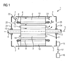
- FIG. 1 shows a basic longitudinal section of a dynamoelectric rotary ventilated machine 1, which has a stator 2 and a rotor 3, the rotor 3 being rotatably connected to a shaft 4 and being rotatably supported about an axis 5.
- the shaft 4 is in principle held on both sides of the active parts, ie the stator 2 and the rotor 3, by a bearing 13, the bearing 13 being positioned by a bearing plate 24.
- the bearing plate 24 is in turn held in a housing 6, the outer walls of which, in this special case, extend axially parallel.
- the stator 2 has axially layered laminations, the laminated core having grooves 9 with an essentially axial course, these grooves 9 being arranged in the region of the air gap 14 of the dynamoelectric rotary machine 1.
- the stator 2 has a winding system in these slots 9, which forms 2 winding heads 8 on the end faces of the laminated core of the stator.
- the stator 2 has cooling channels 10 which run parallel to the axis and which, viewed in the circumferential direction, are arranged in a uniformly distributed manner.
- the cooling channels 10 are preferably round or rounded, but can also have other geometric cross-sectional shapes, such as star-shaped, triangular, etc.
- the rotor 3 is designed as a short-circuit rotor, a short-circuit cage is located on the end faces of the rotor 3 facing the air gap 14, which forms 3 short-circuit rings 12 on the end faces of the rotor.
- a short-circuit cage of the rotor 3 and the shaft 4 Between the short-circuit cage of the rotor 3 and the shaft 4, one or more axially extending cooling channels 11 are arranged in the circumferential direction, which can also be provided in the stator 2.
- the housing 6 and / or the end shield 24 have openings 7 and 25, respectively, through which a - preferably forced - air exchange with the surroundings takes place. These openings 7 and 25 can be covered by filter mats or the like in order to provide a pre-filtering of the cooling air.
- the air flows are guaranteed by one or more fans. There is self-cooling and / or external cooling.
- FIG. 1 shows an example of a cooling air flow 22, as it penetrates into the dynamoelectric rotary machine 1, extends over the axially extending cooling channels 10, 11 and the air gap 14 and, like the heated cooling air flow, again through openings 7 and 25, the housing 6 or the rotary dynamoelectric machine 1 leaves.
- an exemplary cooling air flow is only in the upper half of this Figure 1 shown.
- the particles carried by the cooling air also reach comparatively high speeds and particularly impact on the winding head 8, particularly on the insulation of the winding head 8. This leads, in particular in the case e.g. dusty operating environment leads to premature wear of the insulation of the winding head 8. Due to the different phases of the winding system, which cross and / or overlap in the winding head 8, this leads to failure of the dynamoelectric machine 1.
- a monitoring element 20 that is to say means for monitoring, is now provided in the winding head 8 or directly on the winding head 8, at least one wire and / or at least one optical waveguide, which is likewise subjected to the abrasion process.
- the wire or the optical waveguide is attacked by the particles, the ohmic resistance or the light falling through the optical waveguide is changed accordingly, which, as part of a check, indicates as a clear indication that the insulation properties of the insulation on the winding overhang 8 are declining.
- such wires or optical waveguides can be attached to the winding head 8 in a specially provided additional layer 19, which lead to a notification of the loss of insulation due to the physical conditions described.
- the wires and / or optical fibers are arranged in one or more layers in the additional layer 19, which is attached directly to the winding head 8 on the insulation of the winding head, preferably glued or held by a bandage.
- a corresponding measurement signal is given to the wire or optical waveguide at predetermined time intervals via a control module 15, which can be positioned, for example, in the converter or directly on the electrical machine 1.
- Corresponding measured values or messages are then stored with the return signal, for example in a memory in or on the control module 15, which can be called up there at any time.
- the measurement data are forwarded to a control center 16, for example by radio 17, classified and evaluated.
- These messages of the insulation resistance, in particular on the winding head 8 can be transmitted to all superordinate system controls, for example in the case of multiple units or mining trucks, in order to provide the driver and / or a control center 16 with messages about the state of his drive system, in particular the insulation system.
- FIG 2 shows, by way of example, an arrangement of such an additional layer 19 on the side of the winding head 8 facing the air gap 14. This is particularly important if an additional fan blade 18 should be attached to the short-circuit ring 12, in particular for radial cooling air guidance and thus an increased impact of the Particles of the cooling air flow at the location of the winding head 8 marked there. The insulation of the winding overhang 8 is thus now monitored by the additional layer 19 or wires and optical waveguides embedded in the insulation material there.
- FIG 3 shows a different entry / course of the cooling air 22 in another guiding form. Also there, due to the increased abrasion on the top of the winding head 8, this area of the winding head 8 is monitored selectively or in terms of area.
- FIG 4 shows in a further arrangement with axial flow the layer of the winding head 8 to be protected, which can also be done by an additional layer 19 with wires and optical fibers or by wires and optical fibers already embedded in the winding head 8.
- FIG 5 shows in a more detailed representation the structure of such an additional layer 19, which contains a plurality of individual wires 20 or optical waveguides, and which specifically according to the embodiment according to FIG 2 is attached to the winding head 8.
- FIG 7 are taken, for example, where a drive of a mining truck is shown.
- this motor essentially corresponds to that in FIG. 1 , only that certain air ducts are specially designed and a cooling air flow 22 is optionally also conducted via a terminal box of the motor, not shown.
- FIG 8 shows a further area of application of such a dynamoelectric machine 1 FIG. 1 when driving a locomotive, the dynamo-electric machine 1 driving a pinion 30 and thus a large wheel 32 via the shaft 4.
- the drive is connected via a torque arm 27 to a bogie, not shown.
- the large wheel 32 is rotatably connected to a wheelset shaft 28, which in turn is rotatably connected to the wheels of a locomotive (shown in dashed lines). Both the wheelset shaft 28 and the shaft 4 are mounted separately via the bearing 29 and bearing 13.
- the large wheel 32 runs in a gear housing 31, in which the means for lubricating the large wheel 32 are also provided.
- FIG. 9 indicates based on FIG 2 in a further representation the arrangement of the wires or optical fibers embedded in the insulation of the winding head 8.
- the wires or optical waveguides are arranged as far as possible on the surface of the insulation of the winding head 8 in order to be able to determine the abrasion and thus the reduction in the insulation as early as possible.
Landscapes
- Engineering & Computer Science (AREA)
- Power Engineering (AREA)
- Physics & Mathematics (AREA)
- General Physics & Mathematics (AREA)
- Microelectronics & Electronic Packaging (AREA)
Claims (6)
- Machine (1) dynamoélectrique à refroidissement par de l'air, notamment machine (1) dynamoélectrique blindée ventilée, comprenant un stator (2), un système d'enroulement, qui forme des têtes (8) de bobine sur les côtés frontaux du stator (2), dans laquelle au moins la tête (8) de bobine a, dans sa couche isolante, au moins un élément (20) de contrôle pour contrôler l'épaisseur isolante de la tête (8) de bobine, l'élément (20) de contrôle ayant au moins un agencement de fibre optique.
- Machine (1) dynamoélectrique à refroidissement par de l'air suivant la revendication 1, caractérisée en ce que l'élément (20) de contrôle est prévu au moins au point de la tête (8) de bobine soumis à un courant (22) d'air de refroidissement.
- Machine (1) dynamoélectrique à refroidissement par de l'air suivant la revendication 1 ou 2, caractérisée en ce que l'élément (20) de contrôle a au moins un agencement de fil métallique.
- Machine (1) dynamoélectrique à refroidissement par de l'air suivant l'une des revendications précédentes, caractérisée en ce qu'une reconnaissance d'état de la résistance d'isolement à la tête (8) de bobine a lieu par l'élément (20) de contrôle.
- Procédé de contrôle de l'état d'isolement d'une tête (8) de bobine d'une machine (1) dynamoélectrique à refroidissement par de l'air, notamment d'une machine (1) dynamoélectrique blindée ventilée, comprenant un stator (2), un système d'enroulement, qui forme des têtes (8) de bobine sur les côtés frontaux du stator (2), dans lequel au moins la tête (8) de bobine a, dans sa couche isolante, au moins un élément (20) de contrôle pour contrôler l'épaisseur isolante de la tête (8) de bobine, l'élément (20) de contrôle ayant au moins un agencement de fibre optique, suivant l'une des revendications précédentes par les stades suivants :- à des intervalles de temps pouvant être donnés à l'avance, on envoie des signaux dans l'élément (20) de contrôle,- on enregistre les signaux de retour de l'élément (20) de contrôle,- on exploite les signaux de retour, de manière à tirer des conclusions sur l'état d'isolement de la tête (8) de bobine.
- Procédé de contrôle de la résistance d'isolement suivant la revendication 5, caractérisé en ce qu'une classification de l'état d'isolement de la tête (8) de bobine a lieu par l'enregistrement des signaux de retour.
Priority Applications (3)
| Application Number | Priority Date | Filing Date | Title |
|---|---|---|---|
| EP14179653.2A EP2983276B2 (fr) | 2014-08-04 | 2014-08-04 | Machine dynamoélectrique dotée d'un dispositif de surveillance d'isolation |
| CN201510482793.XA CN105337460B (zh) | 2014-08-04 | 2015-08-03 | 具有绝缘监控的机电机器 |
| US14/816,806 US9784793B2 (en) | 2014-08-04 | 2015-08-03 | Dynamo-electric machine with insulation monitoring |
Applications Claiming Priority (1)
| Application Number | Priority Date | Filing Date | Title |
|---|---|---|---|
| EP14179653.2A EP2983276B2 (fr) | 2014-08-04 | 2014-08-04 | Machine dynamoélectrique dotée d'un dispositif de surveillance d'isolation |
Publications (3)
| Publication Number | Publication Date |
|---|---|
| EP2983276A1 EP2983276A1 (fr) | 2016-02-10 |
| EP2983276B1 EP2983276B1 (fr) | 2017-04-26 |
| EP2983276B2 true EP2983276B2 (fr) | 2020-01-29 |
Family
ID=51260754
Family Applications (1)
| Application Number | Title | Priority Date | Filing Date |
|---|---|---|---|
| EP14179653.2A Active EP2983276B2 (fr) | 2014-08-04 | 2014-08-04 | Machine dynamoélectrique dotée d'un dispositif de surveillance d'isolation |
Country Status (3)
| Country | Link |
|---|---|
| US (1) | US9784793B2 (fr) |
| EP (1) | EP2983276B2 (fr) |
| CN (1) | CN105337460B (fr) |
Families Citing this family (7)
| Publication number | Priority date | Publication date | Assignee | Title |
|---|---|---|---|---|
| JP6874588B2 (ja) * | 2017-08-10 | 2021-05-19 | トヨタ自動車株式会社 | 回転電機ステータ |
| EP3490115A1 (fr) * | 2017-11-28 | 2019-05-29 | Siemens Aktiengesellschaft | Boîte à bornes intégrée d'une machine dynamoélectrique rotative |
| US20190363598A1 (en) * | 2018-05-25 | 2019-11-28 | GM Global Technology Operations LLC | Apparatus for cooling an electric motor and method of making the same |
| DE102020216230A1 (de) * | 2020-12-18 | 2022-06-23 | Zf Friedrichshafen Ag | Elektrische Maschine zum Antrieb eines Kraftfahrzeugs |
| JP2022106469A (ja) * | 2021-01-07 | 2022-07-20 | トヨタ自動車株式会社 | モータ制御装置 |
| CN118243326B (zh) * | 2024-05-21 | 2024-07-16 | 中国航空工业集团公司沈阳空气动力研究所 | 一种具备轴绝缘自监测功能的风洞驱动系统 |
| FR3164578A1 (fr) * | 2024-07-12 | 2026-01-16 | Safran Electrical & Power | Dispositif et procédé de protection contre un défaut dans un moteur électrique |
Citations (8)
| Publication number | Priority date | Publication date | Assignee | Title |
|---|---|---|---|---|
| DD205540A1 (de) † | 1982-03-30 | 1983-12-28 | Elektromasch Forsch Entw | Anordnung zur lebensdauerueberwachung der wicklungsisolation insbesondere fuer elektrische maschinen |
| JPH02184204A (ja) † | 1989-01-05 | 1990-07-18 | Toshiba Corp | 車両用リニアモータのコイルカバー |
| KR20040075187A (ko) † | 2003-02-20 | 2004-08-27 | 한국전기연구원 | 함침 절연 고압 회전기의 권선 단말에 설치 가능한 운전중부분방전 측정센서 |
| EP1503218A1 (fr) † | 2002-04-26 | 2005-02-02 | Kabushiki Kaisha Toshiba | Procede et systeme de diagnostic de deterioration de bobine |
| US20070194631A1 (en) † | 2005-03-15 | 2007-08-23 | Mitsubishi Electric Corporation | Steel wheel-type linear motor |
| EP2479583A2 (fr) † | 2011-01-19 | 2012-07-25 | Hitachi, Ltd. | Procédé de test à décharge partielle de machine électrique rotative commandée par onduleur |
| EP2549245A1 (fr) † | 2011-07-20 | 2013-01-23 | Siemens Aktiengesellschaft | Procédé et dispositif de surveillance d'oscillations de la tête de bobine d'un générateur |
| DE102011082358A1 (de) † | 2011-09-08 | 2013-03-14 | Siemens Aktiengesellschaft | Überwachungseinrichtung für elektrische Betriebsmittel |
Family Cites Families (7)
| Publication number | Priority date | Publication date | Assignee | Title |
|---|---|---|---|---|
| JPS55122450A (en) | 1979-03-16 | 1980-09-20 | Hitachi Ltd | Device for detecting deterioration in insulation of stator coil of rotary electric machine |
| DE3543927A1 (de) * | 1985-12-12 | 1987-06-19 | Kraftwerk Union Ag | Verfahren zur teilentladungserfassung und abreissfunkenmessung bei dynamoelektrischen hochspannungsmaschinen sowie einrichtung zu seiner durchfuehrung |
| US4940933A (en) * | 1989-04-13 | 1990-07-10 | Westinghouse Electric Corp. | Fiber optic arc monitor |
| US6218757B1 (en) * | 1998-11-30 | 2001-04-17 | General Electric Canada Inc | Minimizing shaft currents in dynamoelectric machines |
| RU2246166C2 (ru) * | 1999-03-24 | 2005-02-10 | Шелл Интернэшнл Рисерч Маатсхаппий Б.В. | Способ динамического контроля внутренних параметров систем электродвигателя |
| JP5433392B2 (ja) * | 2009-12-16 | 2014-03-05 | 日立オートモティブシステムズ株式会社 | 電動車両用回転電機、駆動制御装置および絶縁診断方法 |
| DE102013201294A1 (de) | 2013-01-28 | 2014-08-14 | Siemens Aktiengesellschaft | Erkennung eines Wicklungszustands einer elektrischen Maschine |
-
2014
- 2014-08-04 EP EP14179653.2A patent/EP2983276B2/fr active Active
-
2015
- 2015-08-03 CN CN201510482793.XA patent/CN105337460B/zh active Active
- 2015-08-03 US US14/816,806 patent/US9784793B2/en active Active
Patent Citations (8)
| Publication number | Priority date | Publication date | Assignee | Title |
|---|---|---|---|---|
| DD205540A1 (de) † | 1982-03-30 | 1983-12-28 | Elektromasch Forsch Entw | Anordnung zur lebensdauerueberwachung der wicklungsisolation insbesondere fuer elektrische maschinen |
| JPH02184204A (ja) † | 1989-01-05 | 1990-07-18 | Toshiba Corp | 車両用リニアモータのコイルカバー |
| EP1503218A1 (fr) † | 2002-04-26 | 2005-02-02 | Kabushiki Kaisha Toshiba | Procede et systeme de diagnostic de deterioration de bobine |
| KR20040075187A (ko) † | 2003-02-20 | 2004-08-27 | 한국전기연구원 | 함침 절연 고압 회전기의 권선 단말에 설치 가능한 운전중부분방전 측정센서 |
| US20070194631A1 (en) † | 2005-03-15 | 2007-08-23 | Mitsubishi Electric Corporation | Steel wheel-type linear motor |
| EP2479583A2 (fr) † | 2011-01-19 | 2012-07-25 | Hitachi, Ltd. | Procédé de test à décharge partielle de machine électrique rotative commandée par onduleur |
| EP2549245A1 (fr) † | 2011-07-20 | 2013-01-23 | Siemens Aktiengesellschaft | Procédé et dispositif de surveillance d'oscillations de la tête de bobine d'un générateur |
| DE102011082358A1 (de) † | 2011-09-08 | 2013-03-14 | Siemens Aktiengesellschaft | Überwachungseinrichtung für elektrische Betriebsmittel |
Non-Patent Citations (1)
| Title |
|---|
| G.C. STONE: "Advancements during the Past Quarter Century on On-line Monitoring of Motor and Generator Winding Insulation", IEEE TRANSACTIONS ON DIELECTRICS AND ELECTRICAL INSULATION, vol. 9, no. 5, October 2002 (2002-10-01) † |
Also Published As
| Publication number | Publication date |
|---|---|
| EP2983276A1 (fr) | 2016-02-10 |
| US9784793B2 (en) | 2017-10-10 |
| US20160033579A1 (en) | 2016-02-04 |
| CN105337460B (zh) | 2019-10-29 |
| CN105337460A (zh) | 2016-02-17 |
| EP2983276B1 (fr) | 2017-04-26 |
Similar Documents
| Publication | Publication Date | Title |
|---|---|---|
| EP2983276B2 (fr) | Machine dynamoélectrique dotée d'un dispositif de surveillance d'isolation | |
| EP2104975A1 (fr) | Induit à aimants permanents présentant des fentes de refroidissement radiales et procédé de réalisation correspondant | |
| EP2422431B1 (fr) | Machine électrique comprenant un rotor et un stator et un dispositif de surveillance de l'entrefer entre le rotor et le stator | |
| DE102014018223A1 (de) | Elektrische Maschine, insbesondere Asynchronmaschine | |
| EP2263010B1 (fr) | Pompe à vide | |
| EP3611828A1 (fr) | Machine tournante dynamoélectrique doté d'un blindage de fente d'aération | |
| EP2065690B1 (fr) | Machine dynamoélectrique dotée d'un système d'enregistrement de la température | |
| EP2860852A1 (fr) | Dispositif de déviation d'au moins une partie d'un fluide de refroidissement s'écoulant dans un espace intercalaire disposé entre un rotor et un stator d'une machine électrique rotative | |
| WO2019206876A1 (fr) | Machine électrique et aéronef électrique hybride | |
| WO2012175160A2 (fr) | Machine électrique dotée d'un dispositif pour surveiller la géométrie du rotor | |
| WO2017050445A1 (fr) | Turbomachine avec palier magnétique | |
| WO2019034680A1 (fr) | Entraînement direct d'un enrouleur de filet dans le domaine du travail des métaux | |
| WO2019223882A1 (fr) | Dispositif d'entraînement électrique avec surveillance d'états | |
| DE102019007870A1 (de) | Elektrische Maschine | |
| DE102020105915A1 (de) | Axialflussmotor sowie fahrerloses Transportfahrzeug | |
| EP2281335B1 (fr) | Dispositif de générateur à contrôle des voies de courant | |
| DE102018208686A1 (de) | Elektrische Maschine und hybrid-elektrisches Luftfahrzeug | |
| DE102010003246A1 (de) | Transversalflussmaschine | |
| EP2647104B1 (fr) | Enroulement de stator comportant plusieurs enroulements de phase | |
| DE102011108591A1 (de) | Überwachungsvorrichtung für eine doppelgespeiste Asynchronmaschine | |
| DE102017000821A1 (de) | Elektrische Antriebseinheit mit intelligenter Wartungsbedarfsüberwachung | |
| EP3032714A1 (fr) | Machine dynamoélectrique avec un système de signalisation pour la reconnaissance de court-circuits dans le système de bobinage | |
| EP3180837A1 (fr) | Corps de rotor pour une machine électrique tournante | |
| EP4462653A1 (fr) | Machine dynamoélectrique numérisée avec modules onduleurs | |
| DE102007053755A1 (de) | Verfahren und Einrichtung zur Überwachung einer Läufertemperatur einer permanent erregten elektrischen Maschine |
Legal Events
| Date | Code | Title | Description |
|---|---|---|---|
| PUAI | Public reference made under article 153(3) epc to a published international application that has entered the european phase |
Free format text: ORIGINAL CODE: 0009012 |
|
| AK | Designated contracting states |
Kind code of ref document: A1 Designated state(s): AL AT BE BG CH CY CZ DE DK EE ES FI FR GB GR HR HU IE IS IT LI LT LU LV MC MK MT NL NO PL PT RO RS SE SI SK SM TR |
|
| AX | Request for extension of the european patent |
Extension state: BA ME |
|
| 17P | Request for examination filed |
Effective date: 20160520 |
|
| RBV | Designated contracting states (corrected) |
Designated state(s): AL AT BE BG CH CY CZ DE DK EE ES FI FR GB GR HR HU IE IS IT LI LT LU LV MC MK MT NL NO PL PT RO RS SE SI SK SM TR |
|
| REG | Reference to a national code |
Ref country code: DE Ref legal event code: R079 Ref document number: 502014003530 Country of ref document: DE Free format text: PREVIOUS MAIN CLASS: H02K0003380000 Ipc: G01R0031340000 |
|
| RIC1 | Information provided on ipc code assigned before grant |
Ipc: G01R 31/34 20060101AFI20161007BHEP Ipc: H02K 3/38 20060101ALI20161007BHEP Ipc: H02K 11/20 20160101ALI20161007BHEP Ipc: G01R 31/12 20060101ALI20161007BHEP |
|
| GRAP | Despatch of communication of intention to grant a patent |
Free format text: ORIGINAL CODE: EPIDOSNIGR1 |
|
| INTG | Intention to grant announced |
Effective date: 20161121 |
|
| GRAS | Grant fee paid |
Free format text: ORIGINAL CODE: EPIDOSNIGR3 |
|
| GRAA | (expected) grant |
Free format text: ORIGINAL CODE: 0009210 |
|
| AK | Designated contracting states |
Kind code of ref document: B1 Designated state(s): AL AT BE BG CH CY CZ DE DK EE ES FI FR GB GR HR HU IE IS IT LI LT LU LV MC MK MT NL NO PL PT RO RS SE SI SK SM TR |
|
| REG | Reference to a national code |
Ref country code: GB Ref legal event code: FG4D Free format text: NOT ENGLISH |
|
| REG | Reference to a national code |
Ref country code: CH Ref legal event code: EP |
|
| REG | Reference to a national code |
Ref country code: AT Ref legal event code: REF Ref document number: 888340 Country of ref document: AT Kind code of ref document: T Effective date: 20170515 |
|
| REG | Reference to a national code |
Ref country code: IE Ref legal event code: FG4D Free format text: LANGUAGE OF EP DOCUMENT: GERMAN |
|
| REG | Reference to a national code |
Ref country code: CH Ref legal event code: NV Representative=s name: SIEMENS SCHWEIZ AG, CH |
|
| REG | Reference to a national code |
Ref country code: DE Ref legal event code: R096 Ref document number: 502014003530 Country of ref document: DE |
|
| RAP2 | Party data changed (patent owner data changed or rights of a patent transferred) |
Owner name: SIEMENS AKTIENGESELLSCHAFT |
|
| REG | Reference to a national code |
Ref country code: NL Ref legal event code: MP Effective date: 20170426 |
|
| REG | Reference to a national code |
Ref country code: LT Ref legal event code: MG4D |
|
| PG25 | Lapsed in a contracting state [announced via postgrant information from national office to epo] |
Ref country code: NL Free format text: LAPSE BECAUSE OF FAILURE TO SUBMIT A TRANSLATION OF THE DESCRIPTION OR TO PAY THE FEE WITHIN THE PRESCRIBED TIME-LIMIT Effective date: 20170426 |
|
| REG | Reference to a national code |
Ref country code: CH Ref legal event code: PCOW Free format text: NEW ADDRESS: WERNER-VON-SIEMENS-STRASSE 1, 80333 MUENCHEN (DE) |
|
| PG25 | Lapsed in a contracting state [announced via postgrant information from national office to epo] |
Ref country code: FI Free format text: LAPSE BECAUSE OF FAILURE TO SUBMIT A TRANSLATION OF THE DESCRIPTION OR TO PAY THE FEE WITHIN THE PRESCRIBED TIME-LIMIT Effective date: 20170426 Ref country code: LT Free format text: LAPSE BECAUSE OF FAILURE TO SUBMIT A TRANSLATION OF THE DESCRIPTION OR TO PAY THE FEE WITHIN THE PRESCRIBED TIME-LIMIT Effective date: 20170426 Ref country code: GR Free format text: LAPSE BECAUSE OF FAILURE TO SUBMIT A TRANSLATION OF THE DESCRIPTION OR TO PAY THE FEE WITHIN THE PRESCRIBED TIME-LIMIT Effective date: 20170727 Ref country code: ES Free format text: LAPSE BECAUSE OF FAILURE TO SUBMIT A TRANSLATION OF THE DESCRIPTION OR TO PAY THE FEE WITHIN THE PRESCRIBED TIME-LIMIT Effective date: 20170426 Ref country code: NO Free format text: LAPSE BECAUSE OF FAILURE TO SUBMIT A TRANSLATION OF THE DESCRIPTION OR TO PAY THE FEE WITHIN THE PRESCRIBED TIME-LIMIT Effective date: 20170726 Ref country code: HR Free format text: LAPSE BECAUSE OF FAILURE TO SUBMIT A TRANSLATION OF THE DESCRIPTION OR TO PAY THE FEE WITHIN THE PRESCRIBED TIME-LIMIT Effective date: 20170426 |
|
| PG25 | Lapsed in a contracting state [announced via postgrant information from national office to epo] |
Ref country code: SE Free format text: LAPSE BECAUSE OF FAILURE TO SUBMIT A TRANSLATION OF THE DESCRIPTION OR TO PAY THE FEE WITHIN THE PRESCRIBED TIME-LIMIT Effective date: 20170426 Ref country code: BG Free format text: LAPSE BECAUSE OF FAILURE TO SUBMIT A TRANSLATION OF THE DESCRIPTION OR TO PAY THE FEE WITHIN THE PRESCRIBED TIME-LIMIT Effective date: 20170726 Ref country code: IS Free format text: LAPSE BECAUSE OF FAILURE TO SUBMIT A TRANSLATION OF THE DESCRIPTION OR TO PAY THE FEE WITHIN THE PRESCRIBED TIME-LIMIT Effective date: 20170826 Ref country code: RS Free format text: LAPSE BECAUSE OF FAILURE TO SUBMIT A TRANSLATION OF THE DESCRIPTION OR TO PAY THE FEE WITHIN THE PRESCRIBED TIME-LIMIT Effective date: 20170426 Ref country code: LV Free format text: LAPSE BECAUSE OF FAILURE TO SUBMIT A TRANSLATION OF THE DESCRIPTION OR TO PAY THE FEE WITHIN THE PRESCRIBED TIME-LIMIT Effective date: 20170426 Ref country code: PL Free format text: LAPSE BECAUSE OF FAILURE TO SUBMIT A TRANSLATION OF THE DESCRIPTION OR TO PAY THE FEE WITHIN THE PRESCRIBED TIME-LIMIT Effective date: 20170426 |
|
| REG | Reference to a national code |
Ref country code: DE Ref legal event code: R026 Ref document number: 502014003530 Country of ref document: DE |
|
| PLBI | Opposition filed |
Free format text: ORIGINAL CODE: 0009260 |
|
| PG25 | Lapsed in a contracting state [announced via postgrant information from national office to epo] |
Ref country code: EE Free format text: LAPSE BECAUSE OF FAILURE TO SUBMIT A TRANSLATION OF THE DESCRIPTION OR TO PAY THE FEE WITHIN THE PRESCRIBED TIME-LIMIT Effective date: 20170426 Ref country code: SK Free format text: LAPSE BECAUSE OF FAILURE TO SUBMIT A TRANSLATION OF THE DESCRIPTION OR TO PAY THE FEE WITHIN THE PRESCRIBED TIME-LIMIT Effective date: 20170426 Ref country code: RO Free format text: LAPSE BECAUSE OF FAILURE TO SUBMIT A TRANSLATION OF THE DESCRIPTION OR TO PAY THE FEE WITHIN THE PRESCRIBED TIME-LIMIT Effective date: 20170426 Ref country code: DK Free format text: LAPSE BECAUSE OF FAILURE TO SUBMIT A TRANSLATION OF THE DESCRIPTION OR TO PAY THE FEE WITHIN THE PRESCRIBED TIME-LIMIT Effective date: 20170426 |
|
| PLAX | Notice of opposition and request to file observation + time limit sent |
Free format text: ORIGINAL CODE: EPIDOSNOBS2 |
|
| 26 | Opposition filed |
Opponent name: SEW-EURODRIVE GMBH & CO. KG Effective date: 20180117 |
|
| PG25 | Lapsed in a contracting state [announced via postgrant information from national office to epo] |
Ref country code: SM Free format text: LAPSE BECAUSE OF FAILURE TO SUBMIT A TRANSLATION OF THE DESCRIPTION OR TO PAY THE FEE WITHIN THE PRESCRIBED TIME-LIMIT Effective date: 20170426 Ref country code: IT Free format text: LAPSE BECAUSE OF FAILURE TO SUBMIT A TRANSLATION OF THE DESCRIPTION OR TO PAY THE FEE WITHIN THE PRESCRIBED TIME-LIMIT Effective date: 20170426 |
|
| PG25 | Lapsed in a contracting state [announced via postgrant information from national office to epo] |
Ref country code: MC Free format text: LAPSE BECAUSE OF FAILURE TO SUBMIT A TRANSLATION OF THE DESCRIPTION OR TO PAY THE FEE WITHIN THE PRESCRIBED TIME-LIMIT Effective date: 20170426 |
|
| REG | Reference to a national code |
Ref country code: FR Ref legal event code: ST Effective date: 20180430 |
|
| REG | Reference to a national code |
Ref country code: IE Ref legal event code: MM4A |
|
| PG25 | Lapsed in a contracting state [announced via postgrant information from national office to epo] |
Ref country code: SI Free format text: LAPSE BECAUSE OF FAILURE TO SUBMIT A TRANSLATION OF THE DESCRIPTION OR TO PAY THE FEE WITHIN THE PRESCRIBED TIME-LIMIT Effective date: 20170426 |
|
| PLBB | Reply of patent proprietor to notice(s) of opposition received |
Free format text: ORIGINAL CODE: EPIDOSNOBS3 |
|
| REG | Reference to a national code |
Ref country code: BE Ref legal event code: MM Effective date: 20170831 |
|
| PG25 | Lapsed in a contracting state [announced via postgrant information from national office to epo] |
Ref country code: LU Free format text: LAPSE BECAUSE OF NON-PAYMENT OF DUE FEES Effective date: 20170804 |
|
| PG25 | Lapsed in a contracting state [announced via postgrant information from national office to epo] |
Ref country code: IE Free format text: LAPSE BECAUSE OF NON-PAYMENT OF DUE FEES Effective date: 20170804 |
|
| PG25 | Lapsed in a contracting state [announced via postgrant information from national office to epo] |
Ref country code: BE Free format text: LAPSE BECAUSE OF NON-PAYMENT OF DUE FEES Effective date: 20170831 Ref country code: FR Free format text: LAPSE BECAUSE OF NON-PAYMENT OF DUE FEES Effective date: 20170831 |
|
| PG25 | Lapsed in a contracting state [announced via postgrant information from national office to epo] |
Ref country code: MT Free format text: LAPSE BECAUSE OF FAILURE TO SUBMIT A TRANSLATION OF THE DESCRIPTION OR TO PAY THE FEE WITHIN THE PRESCRIBED TIME-LIMIT Effective date: 20170426 |
|
| GBPC | Gb: european patent ceased through non-payment of renewal fee |
Effective date: 20180804 |
|
| PG25 | Lapsed in a contracting state [announced via postgrant information from national office to epo] |
Ref country code: HU Free format text: LAPSE BECAUSE OF FAILURE TO SUBMIT A TRANSLATION OF THE DESCRIPTION OR TO PAY THE FEE WITHIN THE PRESCRIBED TIME-LIMIT; INVALID AB INITIO Effective date: 20140804 |
|
| PG25 | Lapsed in a contracting state [announced via postgrant information from national office to epo] |
Ref country code: CY Free format text: LAPSE BECAUSE OF FAILURE TO SUBMIT A TRANSLATION OF THE DESCRIPTION OR TO PAY THE FEE WITHIN THE PRESCRIBED TIME-LIMIT Effective date: 20170426 Ref country code: GB Free format text: LAPSE BECAUSE OF NON-PAYMENT OF DUE FEES Effective date: 20180804 |
|
| PG25 | Lapsed in a contracting state [announced via postgrant information from national office to epo] |
Ref country code: MK Free format text: LAPSE BECAUSE OF FAILURE TO SUBMIT A TRANSLATION OF THE DESCRIPTION OR TO PAY THE FEE WITHIN THE PRESCRIBED TIME-LIMIT Effective date: 20170426 |
|
| PUAH | Patent maintained in amended form |
Free format text: ORIGINAL CODE: 0009272 |
|
| STAA | Information on the status of an ep patent application or granted ep patent |
Free format text: STATUS: PATENT MAINTAINED AS AMENDED |
|
| REG | Reference to a national code |
Ref country code: CH Ref legal event code: AELC |
|
| 27A | Patent maintained in amended form |
Effective date: 20200129 |
|
| AK | Designated contracting states |
Kind code of ref document: B2 Designated state(s): AL AT BE BG CH CY CZ DE DK EE ES FI FR GB GR HR HU IE IS IT LI LT LU LV MC MK MT NL NO PL PT RO RS SE SI SK SM TR |
|
| REG | Reference to a national code |
Ref country code: DE Ref legal event code: R102 Ref document number: 502014003530 Country of ref document: DE |
|
| PG25 | Lapsed in a contracting state [announced via postgrant information from national office to epo] |
Ref country code: TR Free format text: LAPSE BECAUSE OF FAILURE TO SUBMIT A TRANSLATION OF THE DESCRIPTION OR TO PAY THE FEE WITHIN THE PRESCRIBED TIME-LIMIT Effective date: 20170426 |
|
| PG25 | Lapsed in a contracting state [announced via postgrant information from national office to epo] |
Ref country code: PT Free format text: LAPSE BECAUSE OF FAILURE TO SUBMIT A TRANSLATION OF THE DESCRIPTION OR TO PAY THE FEE WITHIN THE PRESCRIBED TIME-LIMIT Effective date: 20170426 |
|
| PG25 | Lapsed in a contracting state [announced via postgrant information from national office to epo] |
Ref country code: AL Free format text: LAPSE BECAUSE OF FAILURE TO SUBMIT A TRANSLATION OF THE DESCRIPTION OR TO PAY THE FEE WITHIN THE PRESCRIBED TIME-LIMIT Effective date: 20170426 |
|
| REG | Reference to a national code |
Ref country code: DE Ref legal event code: R081 Ref document number: 502014003530 Country of ref document: DE Owner name: INNOMOTICS GMBH, DE Free format text: FORMER OWNER: SIEMENS AKTIENGESELLSCHAFT, 80333 MUENCHEN, DE |
|
| REG | Reference to a national code |
Ref country code: DE Ref legal event code: R081 Ref document number: 502014003530 Country of ref document: DE Owner name: INNOMOTICS GMBH, DE Free format text: FORMER OWNER: INNOMOTICS GMBH, 90441 NUERNBERG, DE |
|
| PGFP | Annual fee paid to national office [announced via postgrant information from national office to epo] |
Ref country code: DE Payment date: 20250827 Year of fee payment: 12 |
|
| REG | Reference to a national code |
Ref country code: AT Ref legal event code: PC Ref document number: 888340 Country of ref document: AT Kind code of ref document: T Owner name: INNOMOTICS GMBH, DE Effective date: 20250909 |
|
| PGFP | Annual fee paid to national office [announced via postgrant information from national office to epo] |
Ref country code: AT Payment date: 20250821 Year of fee payment: 12 |
|
| PGFP | Annual fee paid to national office [announced via postgrant information from national office to epo] |
Ref country code: CH Payment date: 20250901 Year of fee payment: 12 |
|
| PGFP | Annual fee paid to national office [announced via postgrant information from national office to epo] |
Ref country code: CZ Payment date: 20250725 Year of fee payment: 12 |