EP2985165A1 - Unité de moteur-roue pour véhicule - Google Patents
Unité de moteur-roue pour véhicule Download PDFInfo
- Publication number
- EP2985165A1 EP2985165A1 EP14782415.5A EP14782415A EP2985165A1 EP 2985165 A1 EP2985165 A1 EP 2985165A1 EP 14782415 A EP14782415 A EP 14782415A EP 2985165 A1 EP2985165 A1 EP 2985165A1
- Authority
- EP
- European Patent Office
- Prior art keywords
- wheel
- shaft
- hub
- displacement
- tooth portion
- Prior art date
- Legal status (The legal status is an assumption and is not a legal conclusion. Google has not performed a legal analysis and makes no representation as to the accuracy of the status listed.)
- Withdrawn
Links
- 238000006073 displacement reaction Methods 0.000 claims abstract description 109
- 238000010521 absorption reaction Methods 0.000 claims abstract description 61
- 230000007246 mechanism Effects 0.000 claims abstract description 59
- 230000008878 coupling Effects 0.000 claims abstract description 42
- 238000010168 coupling process Methods 0.000 claims abstract description 42
- 238000005859 coupling reaction Methods 0.000 claims abstract description 42
- 230000005540 biological transmission Effects 0.000 claims abstract description 32
- 239000002344 surface layer Substances 0.000 claims description 4
- 230000000694 effects Effects 0.000 description 11
- 238000003780 insertion Methods 0.000 description 10
- 230000037431 insertion Effects 0.000 description 10
- 238000007789 sealing Methods 0.000 description 9
- 238000005192 partition Methods 0.000 description 5
- 230000009467 reduction Effects 0.000 description 5
- 239000003921 oil Substances 0.000 description 4
- 230000009471 action Effects 0.000 description 3
- 239000003570 air Substances 0.000 description 3
- 238000005255 carburizing Methods 0.000 description 3
- 230000002093 peripheral effect Effects 0.000 description 3
- XLYOFNOQVPJJNP-UHFFFAOYSA-N water Substances O XLYOFNOQVPJJNP-UHFFFAOYSA-N 0.000 description 3
- 230000008859 change Effects 0.000 description 2
- 239000000470 constituent Substances 0.000 description 2
- 239000004519 grease Substances 0.000 description 2
- 230000001050 lubricating effect Effects 0.000 description 2
- 238000000034 method Methods 0.000 description 2
- 230000036961 partial effect Effects 0.000 description 2
- 238000010791 quenching Methods 0.000 description 2
- 230000000171 quenching effect Effects 0.000 description 2
- 238000005480 shot peening Methods 0.000 description 2
- 229910000576 Laminated steel Inorganic materials 0.000 description 1
- 229910000831 Steel Inorganic materials 0.000 description 1
- 230000002159 abnormal effect Effects 0.000 description 1
- 238000007792 addition Methods 0.000 description 1
- 239000012080 ambient air Substances 0.000 description 1
- 230000004323 axial length Effects 0.000 description 1
- 238000004891 communication Methods 0.000 description 1
- 238000007796 conventional method Methods 0.000 description 1
- 238000013461 design Methods 0.000 description 1
- 230000006866 deterioration Effects 0.000 description 1
- 230000002401 inhibitory effect Effects 0.000 description 1
- 239000007788 liquid Substances 0.000 description 1
- 239000010687 lubricating oil Substances 0.000 description 1
- 238000005461 lubrication Methods 0.000 description 1
- 238000012423 maintenance Methods 0.000 description 1
- 239000002184 metal Substances 0.000 description 1
- 230000008569 process Effects 0.000 description 1
- 230000002829 reductive effect Effects 0.000 description 1
- 230000008929 regeneration Effects 0.000 description 1
- 238000011069 regeneration method Methods 0.000 description 1
- 239000011347 resin Substances 0.000 description 1
- 229920005989 resin Polymers 0.000 description 1
- 230000000717 retained effect Effects 0.000 description 1
- 238000004904 shortening Methods 0.000 description 1
- 239000010959 steel Substances 0.000 description 1
- 230000001360 synchronised effect Effects 0.000 description 1
- 230000000699 topical effect Effects 0.000 description 1
- 238000012546 transfer Methods 0.000 description 1
- 238000004804 winding Methods 0.000 description 1
Images




Classifications
-
- B—PERFORMING OPERATIONS; TRANSPORTING
- B60—VEHICLES IN GENERAL
- B60K—ARRANGEMENT OR MOUNTING OF PROPULSION UNITS OR OF TRANSMISSIONS IN VEHICLES; ARRANGEMENT OR MOUNTING OF PLURAL DIVERSE PRIME-MOVERS IN VEHICLES; AUXILIARY DRIVES FOR VEHICLES; INSTRUMENTATION OR DASHBOARDS FOR VEHICLES; ARRANGEMENTS IN CONNECTION WITH COOLING, AIR INTAKE, GAS EXHAUST OR FUEL SUPPLY OF PROPULSION UNITS IN VEHICLES
- B60K7/00—Disposition of motor in, or adjacent to, traction wheel
- B60K7/0007—Disposition of motor in, or adjacent to, traction wheel the motor being electric
-
- B—PERFORMING OPERATIONS; TRANSPORTING
- B60—VEHICLES IN GENERAL
- B60B—VEHICLE WHEELS; CASTORS; AXLES FOR WHEELS OR CASTORS; INCREASING WHEEL ADHESION
- B60B27/00—Hubs
- B60B27/0015—Hubs for driven wheels
-
- B—PERFORMING OPERATIONS; TRANSPORTING
- B60—VEHICLES IN GENERAL
- B60K—ARRANGEMENT OR MOUNTING OF PROPULSION UNITS OR OF TRANSMISSIONS IN VEHICLES; ARRANGEMENT OR MOUNTING OF PLURAL DIVERSE PRIME-MOVERS IN VEHICLES; AUXILIARY DRIVES FOR VEHICLES; INSTRUMENTATION OR DASHBOARDS FOR VEHICLES; ARRANGEMENTS IN CONNECTION WITH COOLING, AIR INTAKE, GAS EXHAUST OR FUEL SUPPLY OF PROPULSION UNITS IN VEHICLES
- B60K17/00—Arrangement or mounting of transmissions in vehicles
- B60K17/04—Arrangement or mounting of transmissions in vehicles characterised by arrangement, location or kind of gearing
- B60K17/043—Transmission unit disposed in on near the vehicle wheel, or between the differential gear unit and the wheel
- B60K17/046—Transmission unit disposed in on near the vehicle wheel, or between the differential gear unit and the wheel with planetary gearing having orbital motion
-
- B—PERFORMING OPERATIONS; TRANSPORTING
- B60—VEHICLES IN GENERAL
- B60K—ARRANGEMENT OR MOUNTING OF PROPULSION UNITS OR OF TRANSMISSIONS IN VEHICLES; ARRANGEMENT OR MOUNTING OF PLURAL DIVERSE PRIME-MOVERS IN VEHICLES; AUXILIARY DRIVES FOR VEHICLES; INSTRUMENTATION OR DASHBOARDS FOR VEHICLES; ARRANGEMENTS IN CONNECTION WITH COOLING, AIR INTAKE, GAS EXHAUST OR FUEL SUPPLY OF PROPULSION UNITS IN VEHICLES
- B60K17/00—Arrangement or mounting of transmissions in vehicles
- B60K17/04—Arrangement or mounting of transmissions in vehicles characterised by arrangement, location or kind of gearing
- B60K17/14—Arrangement or mounting of transmissions in vehicles characterised by arrangement, location or kind of gearing the motor of fluid or electric gearing being disposed in, or adjacent to, traction wheel
-
- F—MECHANICAL ENGINEERING; LIGHTING; HEATING; WEAPONS; BLASTING
- F16—ENGINEERING ELEMENTS AND UNITS; GENERAL MEASURES FOR PRODUCING AND MAINTAINING EFFECTIVE FUNCTIONING OF MACHINES OR INSTALLATIONS; THERMAL INSULATION IN GENERAL
- F16D—COUPLINGS FOR TRANSMITTING ROTATION; CLUTCHES; BRAKES
- F16D3/00—Yielding couplings, i.e. with means permitting movement between the connected parts during the drive
- F16D3/16—Universal joints in which flexibility is produced by means of pivots or sliding or rolling connecting parts
- F16D3/18—Universal joints in which flexibility is produced by means of pivots or sliding or rolling connecting parts the coupling parts (1) having slidably-interengaging teeth
- F16D3/185—Universal joints in which flexibility is produced by means of pivots or sliding or rolling connecting parts the coupling parts (1) having slidably-interengaging teeth radial teeth connecting concentric inner and outer coupling parts
-
- B—PERFORMING OPERATIONS; TRANSPORTING
- B60—VEHICLES IN GENERAL
- B60K—ARRANGEMENT OR MOUNTING OF PROPULSION UNITS OR OF TRANSMISSIONS IN VEHICLES; ARRANGEMENT OR MOUNTING OF PLURAL DIVERSE PRIME-MOVERS IN VEHICLES; AUXILIARY DRIVES FOR VEHICLES; INSTRUMENTATION OR DASHBOARDS FOR VEHICLES; ARRANGEMENTS IN CONNECTION WITH COOLING, AIR INTAKE, GAS EXHAUST OR FUEL SUPPLY OF PROPULSION UNITS IN VEHICLES
- B60K7/00—Disposition of motor in, or adjacent to, traction wheel
- B60K2007/0038—Disposition of motor in, or adjacent to, traction wheel the motor moving together with the wheel axle
-
- B—PERFORMING OPERATIONS; TRANSPORTING
- B60—VEHICLES IN GENERAL
- B60K—ARRANGEMENT OR MOUNTING OF PROPULSION UNITS OR OF TRANSMISSIONS IN VEHICLES; ARRANGEMENT OR MOUNTING OF PLURAL DIVERSE PRIME-MOVERS IN VEHICLES; AUXILIARY DRIVES FOR VEHICLES; INSTRUMENTATION OR DASHBOARDS FOR VEHICLES; ARRANGEMENTS IN CONNECTION WITH COOLING, AIR INTAKE, GAS EXHAUST OR FUEL SUPPLY OF PROPULSION UNITS IN VEHICLES
- B60K7/00—Disposition of motor in, or adjacent to, traction wheel
- B60K2007/0092—Disposition of motor in, or adjacent to, traction wheel the motor axle being coaxial to the wheel axle
Definitions
- the present invention relates to an in-wheel motor unit for a vehicle in which a drive output shaft of the drive unit body and a wheel hub shaft supported by the hub bearing with respect to a case member are linked or connected via a displacement absorption mechanism.
- an in-wheel motor for a vehicle in which a drive output shaft and a wheel hub shaft supported by a hub bearing is connected via a displacement absorption mechanism.
- the displacement absorption mechanism is intended to prevent or suppress the displacement / inclination of the hub bearing from being transmitted to a gear train or an electric motor accommodated in the drive unit to thereby prevent or suppress the impact on a gear meshing portion or the motor (for example, see Patent Document 1).
- a hub is provided at the distal end of a shaft portion extending to the wheel side from the displacement absorbing mechanism.
- a wheel is structured to be fixed or mounted via bolts on a mounting surface of the hub.
- Patent Document 1 JP 2009-190440 A
- the total length in the axial direction of the displacement absorbing mechanism is disposed on the interior side of the vehicle with respect to the wheel mounting surface. Therefore, with respect to the position of the wheel, the drive unit body is shifted toward the interior side by the entire length in the axial direction of the displacement absorbing mechanism, which could deteriorate vehicle mountability. Further, when the drive unit body is placed forcibly in the vehicle outer side, the axial span of the displacement absorption mechanism is shortened so that there is a possibility that the displacement absorbing performance is consequently lowered.
- the present invention has been made in consideration of the above problems, and an object thereof is to provide an in-wheel motor unit for a vehicle, which makes it possible to achieve both the ensuring of the vehicle mountability and the displacement absorbing performance.
- the present invention comprises a drive output shaft of a drive unit body, a wheel hub shaft supported on a hub bearing, a displacement absorption mechanism configured to link the drive output shaft and the wheel hub shaft, an output shaft side drive transmission engaging or fitting portion meshed with a first inner tooth portion of the drive output shaft and a first outer tooth portion of a gear coupling shaft, and a hub shaft side drive transmission engaging or fitting portion meshed with a second inner tooth portion of the wheel hub shaft and a second outer tooth portion of the gear coupling shaft, wherein the second outer tooth portion of the gear coupling shaft of the displacement absorption mechanism is configured to be disposed axially in the vehicle outer side with respect to a wheel mounting surface of the wheel hub shaft, on which a wheel is attached or mounted.
- the second outer tooth portion of the gear coupling shaft of the displacement absorption mechanism is configured to be disposed axially in the vehicle outer or exterior side with respect to a wheel mounting surface of the wheel hub shaft.
- the drive unit body may be placed in the vehicle outer side to suppress the axial dimension of the entire unit to thereby achieve excellent automotive layout properties.
- the axial span of the displacement absorption mechanism can be secured longer, so that it is possible to obtain a higher displacement absorption performance compared to the displacement absorption mechanism of shorter span.
- the configuration of the vehicle in-wheel motor unit in the first embodiment is described separately in [schematic configuration of the entire unit], [detailed configuration of the drive unit body], [detailed configuration of displacement absorption mechanism], [detailed configuration of wheel structure], [detailed configuration of assembly structure of gear coupling axis], and [detailed configuration of the periphery of axle case], respectively.
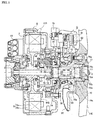
- FIG. 1 showing an overall cross-section of the in-wheel motor unit for a vehicle
- the in-wheel motor unit for the vehicle is applied to the left and right rear wheels and the like of an electric vehicle.
- a drive unit body A, a displacement absorption unit B, and a wheel structure C are provided.
- the driving unit body A has a function as a driving source that is installed to each of the left and right rear wheels, and is provided with a motor generator MG and a gear train GT.
- a motor generator MG During power running of the motor-generator MG, by applying to a stator coil 9b which is wound around a stator 9 a three-phase alternating current, a motor shaft 6 integral with the rotor is rotated. The rotation speed of the motor shaft 6 is output to the drive shaft 10 with its speed reduced by a gear train GT.
- the rotation speed input from the drive output shaft 10 is accelerated by the gear train GT to rotate the motor shaft 6 and the rotor 8.
- three-phase alternating current is generated in the stator coil 9b of the stator 9, which is disposed over the rotor 8 with air gap.
- the displacement absorption mechanism B has a function to prevent / inhibit to transfer displacement / inclination of the hub bearing 71 to the motor-generator MG and gear train GT of the drive unit body A, and is provided with a gear coupling shaft 50.
- the gear coupling shaft 50 connects or links
- the drive output shaft 10 of the drive unit body A and a wheel hub shaft 70 which is supported on a hub bearing 71 with respect to an axle case 72 (case member) are linked or connected by the gear coupling shaft in such a way that the displacement or inclination may be absorbed.
- the wheel structure C has a function of mounting a tire and a brake mechanism of an associated wheel, and is provided with a wheel hub axle 70.
- the wheel hub shaft 70 with respect to the axle case 72, is rotatably supported by a hub bearing 71 of the double row angular contact bearing structure.
- a brake disk 73 and the tire wheel 110 are mounted or fixed.
- the wheel hub shaft 70 is connected to the drive output shaft 10 of the drive unit body A via the displacement absorption mechanism B.
- FIG. 2 shows a configuration of the in-wheel motor unit for a vehicle in which a drive unit body A, a displacement absorbing mechanism B, and a wheel structure C are illustrated separately or divided from each other.
- a description is given of the detailed configuration of the drive unit body A.
- the drive unit body A is configured to accommodate, within the unit case member 100, a motor-generator MG with the embedded magnet synchronous motor structure of three-phase alternating current type, and a gear train GT with a planetary gear type reduction gear mechanism.
- the unit case member 100 is configured to include a unit case 1, a unit cover 2, a motor shaft side cover 3, and an output shaft side cover 4.
- the unit cover 2 is bolted to one end of the unit case 1, and the motor shaft side cover 3 is bolted to the unit cover 2 so as to close that one end of the motor shaft 6.
- the output shaft side cover 4 is bolted to the other end of the unit case 1 so as to allow part of the drive output shaft 10 to project from the drive unit body A.
- an oil seal 5 is mounted on an end position of the output shaft side cover 4, and the portion of the oil seal 5 is made in contact with the outer circumferential surface of the drive output shaft 10 at a predetermined sealing pressure for sealing. That is, the output shaft-side cover 4 and the oil seal 5 serve as a partition structure member for separating the drive unit body A and the hub bearing 71.
- the motor generator MG is configured to include the motor shaft 6, a rotor flange 7, the rotor 8, and the stator 9.
- the motor shaft 6 is rotatably supported at its one end through a first bearing 11 relative to the unit cover 2, and is supported at its other end relatively rotatably via a second bearing 12 against the drive output shaft 10.
- the rotor 8 is fitted to the rotor flange 7 which in turn is fixed to the motor shaft 6 and is constituted by laminated steel plates with permanent magnet embedded (not shown).
- the stator 9 is fixed to the inner surface of the unit case 1, and is arranged with an air gap with respect to the rotor 8.
- the stator 9 is constructed by winding the stator coil 9b to each of the stator teeth 9a composed of laminated punched steel sheets.
- stator coil 9b is connected with wiring harness via connection terminals 15 which is divided into U-, V-, and W- phase.
- motor shaft 6 is formed with an axis oil path 16 for lubricating oil for lubricating required sites such as the gear meshing portion of the gear train GT and bearings, etc.
- the gear train GT is disposed on the right side space of the rotor flange 7 in FIG. 1 , and includes a sun gear 17, a large pinion 18, a small pinion 19, a pinion carrier 20, and a ring gear 21.
- a planetary gear type reduction gear mechanism to reduce an input speed to a slower output speed is constituted by assigning the sun gear for input, the pinion carrier for output, while fixing the ring gear.
- the sun gear 17 is formed integrally with the motor shaft 6, meshing with the large pinion 18.
- the large pinion 18 and the small pinion 19 are positioned adjacent to each other and formed integrally and are rotatably supported with respect to the pinion carrier 20.
- the ring gear 21 is coupled to the unit case 1 through serration so as to be fixed to the rotating direction.
- the ring gear meshes with the small pinion 19.
- the drive output shaft 10 is provided integrally with the pinion carrier 20.
- the drive output shaft 10 is formed in a cylindrical sleeve shape, one end of which extends axially to the inside of the small pinion 19 while the other end of which extends in the axial direction to the other end so as to protrude from the output shaft side cover 4.
- This rotation support structure of the drive output shaft 10 is intended for the pinion carrier 20 as well so as to be rotatably supported by a third bearing 13 with respect to the motor shaft 6 and to be rotatably supported by a fourth bearing 14 with respect to the output shaft side cover 4.
- a septum or partition seal member 22 is arranged in an oil-tight state in the inner surface of the drive output shaft 10 at a position separating the motor shaft 6 and the gear coupling shaft 50.
- the partition seal member 22 is intended to act as a partition wall structure member to isolate the drive unit body A from the displacement absorption mechanism B.
- a resolver 23 for detecting the rotation angle of the motor and a parking gear 24 for fixing the motor shaft 6 through engagement with a parking pawl (not shown) are arranged.
- FIG. 2 shows a configuration of the in-wheel motor unit for a vehicle in which a drive unit body A, a displacement absorbing mechanism B, and a wheel structure C are separated or divided from each other.
- FIG. 3 is an enlarged sectional view showing enlargement of the displacement absorption mechanism that represents the essential constituent. Below, with reference to FIGS. 1 to 3 , a detailed description is given of the structure of the displacement absorption mechanism B.
- the displacement absorption mechanism B shown in FIG. 1 is configured such that the gear coupling shaft 50 that is replaceable per se or independently may be fitted or engaged with the drive output shaft 10 and the wheel hub shaft 70 for drivable transmission while absorbing displacement.
- the gear coupling shaft 50 is structured such that a first outer teeth portion 52 and a first end portion 53 are provided on one end of the gear coupling shaft portion 51 while a second outer teeth portion 54 and a second end portion 55 are provided on the other end of the gear coupling shaft portion 51.
- the first outer teeth portion 52 is serration-fitted to the first inner teeth portion 56 of the drive output shaft 10 so as to be capable of absorbing displacement.
- the first end portion 53 is structured to be capable of contacting with the partition seal member 22 via a spherical surface.
- the second outer teeth portion 54 is serration-fitted to the second inner teeth portion 57 of the wheel hub shaft 70 so as to be capable of absorbing displacement.
- the second end portion 55 is structured to be capable of contacting with the end cap sealing member 96 via spherical surface.
- the top surface and the bottom surface of the inner teeth extend straight in the axial direction and thus are formed in a cylindrical shape.
- the first outer tooth portion 52 and the second outer tooth portion 54 the top surface and the bottom surface of the outer teeth are formed in a spherical shape.
- the first outer tooth portion 52 and the second outer tooth portion 54 are formed in crowning profile or shape in which the tooth thickness is widened in the central portion while the tooth thickness is narrower toward the both ends (see FIG. 3 ).
- Such a structure is achieved in which the inclination in any direction with the inclination center D or the inclination center E may be absorbed.
- the first end 53 and second end 55 are respectively formed in a smooth spherical surface with the axis center position representing the maximum protruding surface, and the inclination about a displacement (stiffness) center point F disposed between the inclination centers is structured to be absorbed. That is, fitting of the first outer teeth portion 52 and the first inner tooth portion 56 represents an output shaft side driving transmission unit 58.Further, fitting between the second outer teeth portion 54 and the second inner tooth portion 57 represents a hub shaft side driving force transmission fitting portion 59 between the gear coupling
- gear coupling shaft 50 is mounted in a coupling space sealed in the entire circumference along with lubricating grease (not shown).
- both axial ends of the gear coupling shaft 50 are formed symmetrically. That is, with respect to the first outer tooth portion 52 and the second outer teeth portion 54, the number of teeth as well as the spherical shape of the top surface and the spherical surface of the bottom surface are formed symmetrically in the axial direction (lateral direction in FIG. 1 ). Also, the first end 53 and the second end 55 are shaped symmetrically in the axial direction (lateral direction in FIG. 1 ). Therefore, the number of teeth of both inner tooth portions 56 and 57 meshing with both outer tooth portions 52 and 54 are also formed in the same number.
- FIG. 2 shows a configuration of the in-wheel motor unit for a vehicle in which a drive unit body A, a displacement absorbing mechanism B, and a wheel structure C are separated or divided from each other.
- FIG. 3 is an enlarged sectional view showing enlargement of the displacement absorption mechanism that represents the essential constituent. Below, with reference to FIGS. 1 to 3 , a detailed description is given of the structure of the displacement absorption mechanism B.
- the wheel structure C is configured to include a wheel hub shaft 70, a hub bearing 71, an axle case 72, a brake disk 73, and a tire wheel 110.
- the wheel hub shaft 70 is a rotating member connected to the drive output shaft 10 via the gear coupling shaft 50 and functions as an inner race of the hub bearing 71.
- the wheel hub shaft 70 is supported by the hub bearing 71 at the end of the cylindrical body 700 in the side of the drive unit body A. Further, on a vehicle exterior side than the position for supporting the hub bearing 71, a hub-side flange part 70a extends from the outer periphery of the cylindrical body 700 at its middle portion in the axial direction.
- a bolt insertion hole 70f penetrates in the hub-side flange part 70a along the axial direction.
- a wheel bolt 75 is pre-fixed in the bolt insertion hole 70f with its shaft portion 75b protruded in the vehicle exterior side to secure the brake disc 73 and tire wheel 110 shown in FIG. 1 jointly by a wheel nut (not shown).
- an end cap sealing member 76 that contacts a second end 55 of the gear coupling shaft 50 is fixed to the end position by a spring pin 77.
- a tire (not shown) is mounted to the peripheral position of the tire-wheel 110,.
- the hub bearing 71 is intended for supporting the wheel hub shaft 70 relative to the axle case 72 and is constituted by double rows of balls to be arranged to have a contact angle with a back-to-back alignment.
- This hub bearing 71 is structured by constructing the wheel hub shaft 70 as an inner race while constructing the axle case 72 as an outer race.
- a surface hardening portions 201,202 which have been subjected to surface hardening treatment by carburizing hardening or shot peening or the like are formed on the ball contact surfaces of the wheel hub shaft 70 and the axle case 72. Note that grease is sealed for lubrication in the hub bearing 71.
- the axle case represents a case member which is fixed by a bolt 78 jointly with the unit case 1 to the output shaft cover 4 and functions as an outer race to the hub bearing 71. Further, a case- side flange part 72b of the axle case 72 represents a brake part for a wheel cylinder 79 to be fixed, and is integrally extended with a brake caliper 81 for supporting a pair of brake shoes 80,80.
- a splash guard 82 is fixed to cover the brake disk 73 in addition to preventing intrusion of muddy water into the hub bearing 71.
- a mud guard 83 is fixed as shown in Fig. 5 to thereby prevent muddy water from intruding in the hub bearing 71 as well as in the sealing member 84 for sealing thereof.
- the mud guard 83 is formed into an L-sectional shape having a cylindrical base portion 83a which is fixed to the cylindrical portion 72a and an annular shielding plate 83b that extends radially outward from the end of the base portion 83a. Further, as shown in FIG. 6 , at the one place in the circumferential direction of the shielding plate 83b, a cutout portion 83c is formed to have a circular arc shape in an inner diameter direction from the outer peripheral edge.
- the axle case 72 as shown in FIG. 1 , is fixed to the output shaft side cover 4 to thereby form a closed space 90 having a liquid sealing property between the drive unit body A and the hub bearing 71.
- An ABS sensor 91 is placed in the closed space 90 for detecting a wheel speed.
- the ABS sensor 91 is provided such that a sensing part 91b is disposed in the upper position of the axle case 72 and penetrates through the closed space 90.
- a sensed part 91b is press-fitted to the wheel hub shaft 70.
- a breather 90 is connected to the closed space 90 for communication with ambient air (see FIG. 3 ).
- the wheel hub shaft 70 is provided with, as shown in FIG. 3 , in the state of being supported by hub bearing 71 relative to the unit case 1, an opening 70b in an axially end (right end in the figure) opposite to the drive unit body A.
- the opening 70b is formed in a larger diameter than a general portion 70c for storing the gear coupling shaft 50 in the cylindrical wheel hub shaft 70 so that the inner diameter is provided for inserting the gear coupling shaft 50.
- a step 70d is formed between the opening portion 70b and the general portion 70c.
- the opening 70b is closed by the end cap seal member 76 described above.
- the end cap seal member 76 is formed in a disc shape and made of a metal or a resin. Further, in the outer peripheral portion, as shown in FIG. 3 , a flange 76f extending in the axial direction are formed. A seal member 76a is provided on the outer periphery of the flange 76f for sealing the closed space 90.
- the end cap sealing member 76 in a state of being abutted against the step portion 70d,is retained and prevented from dropping off the opening portion 70b by a spring pin 77 as detachable member. has been made and the retaining of the opening 70b by the spring pin 77 of the detachable member. More specifically, a pair of insertion holes 70e, 70e is opened in the wheel hub shaft 70 to penetrate in a direction perpendicular to the axis.
- a flange portion 76f of the end cap seal member 76 is formed with, seen in the radial direction, U-shaped cut-out portions 76b, 76b at the upper and lower position radially coaxially with the insertion holes 70e, 70e for inserting spring pins.
- the insertion holes 70e, 70e are covered by an inner periphery of an attachment hole 111 of the tire wheel 110 which is mounted to the wheel hub shaft 70.
- the spring pin is prevented from being drop off by the tire wheel.
- the attachment hole 11 is closed by a cap 112 so that entry of muddy water into the end cap seal member 76 and the spring pin 77 is restricted.
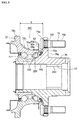
- the axle case 72 is provided with a cylindrical portion 72a for supporting the hub bearing 71 and a case- side flange part 72b which extends in the outer diameter direction in a disc shape from the cylindrical portion 72a at the end of the drive unit body A and which is fixed to the output shaft side cover 4.
- a space 140 is provided between the case-side flange part 72b and the hub-side flange part 70a of the wheel hub shaft 70.
- the space 140 serves as a space for the mounting and demounting work of the wheel bolt 75 to and from the hub-side flange part 70a.
- the axle case 72 if formed with a work groove 72c at the corner portion between the cylindrical portion 72a and the case-side flange part 72b.
- the work groove 72c is provided at one place in the circumferential direction of the cylindrical portion 72a of the axle case 72.
- the operation groove 72c is formed.
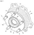
- the operation groove 72c as shown in the perspective view of FIG. 7 , is provided at one place in the circumferential direction in the cylindrical part 72a of the axle case 72.
- this work groove 72c is, as viewed from the axial direction, formed to extend radially (in the up and down direction in the figure) in the center of the lateral direction so as to be symmetrical when viewed from the axial direction.
- the operation groove 72c is intended to prevent mounting and dismounting of the wheel bolt 75 from interference between a head portion 75a of the wheel bolt 75 and the axle case 72 when attaching and detaching the wheel bolt 75 in the bolt insertion hole 70f.
- the axial dimension L (see FIG. 5 ) of the space 140 between the case-side flange part 72b and the hub-side flange part 70a is shorter than the axial length of the wheel bolt 75 so as to be too narrow for the wheel bolt to be attached to or detached from the bolt insertion hole 70f. That is, with the axial dimension L, in a state (Sa) in FIG. 8 , in which the tip of the shaft portion 75b shown is inserted in the entrance of the bolt hole 70f, when an attempt is made to further insert the shaft portion 75b as shown by (Sb), then the head portion 75a comes to interfere with the axle case 72.
- the axle case 72 is formed with the operation groove 72c, and the depth of the operation groove 72c is formed with a depth such that the head portion 75a would not interfere with the axle case 72 and separated from the hub-side flange part 70a.
- the operation groove 72 is formed at only one location so as to minimize the stiffness reduction by forming the operation groove 72c.
- the axle case 72c when providing at one place in the circumferential direction of the axle case 72, as viewed from the axial direction, is located at the one upper. laterally symmetrical position, when attaching to a vehicle body (not shown), the axle case may be commonly used for left and right wheels.
- the hub-side flange part 70a erects in the axially middle portion of the wheel hub shaft 70.
- the outer face of the hub-side flange part 70a (right side in the figure) provides for a wheel mounting surface 70g.
- a brake disc 73 is sandwiched between the wheel mounting surface 70g and the tire-wheel 110.
- the second outer tooth portion 54 for engagement with the wheel hub shaft 70 of the gear coupling shaft 50 forming the displacement absorption mechanism B is arranged in the axial direction on the exterior side of the vehicle, i.e., axially in the vehicle exterior side (right side in the figure).
- the hub bearing 71 is disposed in the drive unit body A side with respect to the hub-side flange part 70a forming the wheel mounting surface 70g.
- the second inner tooth portion 57 is provided in a position away to the outside of the vehicle direction with respect to the portion that supports the hub bearing 71.
- the second inner tooth portion 57 is provided on the surface layer thereof with a surface hardening portion 203 through carburizing quenching, shot peening or the like.
- the first inner tooth portion 56 of the drive output shaft 10, both outer tooth portions 52, 54 of the gear coupling shaft 50 are formed with a similar surface hardening portion (not shown) in a similar manner.
- the hub bearing 71 is disposed somewhere in the middle position between the output shaft side drive transmission fitting portion 58 and the hub shaft side drive transmission fitting portion 59.
- the displacement absorption mechanism is required to prevent/suppress the effects on the gear meshing portions or the motor-generator MG by preventing / inhibiting to transmit the displacement / inclination of the wheel hub shaft 70 to the gear train GT and the motor-generator MG.
- FIGS. 4A to 4D a description is given of the displacement absorption operation of the displacement absorption mechanism B.
- the parallel displacement may be absorbed through an inclination action of two universal joints of the output shaft side drive transmission fitting portion 58 and the hub side drive transmission fitting portion 59.
- the parallel displacement of the wheel hub shaft 70 is free from affecting the drive output shaft 10 to displace.
- the inclination displacement may be absorbed through an action of two universal joints of the output shaft side drive transmission fitting portion 58 and the hub side drive transmission fitting portion 59 via an inclination of the gear coupling shaft 50 shown in the figure.
- the inclination displacement of the wheel hub shaft 70 is free from affecting the drive output shaft 10 to displace.
- the axial displacement may be absorbed through a sliding action of at least one of the universal joints of the output shaft side drive transmission fitting portion 58 and the hub side drive transmission fitting portion 59.
- the axial displacement of the wheel hub shaft 70 is free from affecting the drive output shaft 10 to displace.
- the displacement of the wheel hub shaft 70 is prevented from being transmitted to the gear train GT and the motor-generator MG from the drive output shaft 10 thanks to the displacement absorbing mechanism B. Consequently, the displacement absorption mechanism would not cause any of the above-mentioned problems (1) to (4).
- the hub bearing when placing the second outer tooth portion of the gear coupling shaft of the displacement absorption mechanism, the hub bearing is arranged axially between the output shaft side drive transmission fitting portion and the hub shaft side drive transmission fitting portion and in a substantially central position.
- the hub shaft side drive transmission fitting portion (second outer tooth portion) is disposed in the vehicle exterior side with respect to the wheel mounting surface, the positions of the hub bearing, the output shaft side drive transmission fitting portion, and the hub shaft side drive transmission fitting portion are not limited thereto.
- the axle case is exemplified as a case member for supporting the wheel hub shaft through the hub bearing.
- the case member is included in the unit case member, the only case member is not limited to the axle case.
- the vehicle in-wheel motor unit according to the present invention is applied to left and right rear wheels of an electric vehicle.
- the vehicle in-wheel motor unit according to the present invention is applicable to the left and right front wheels, or all wheels of the electric vehicle.
Landscapes
- Engineering & Computer Science (AREA)
- Mechanical Engineering (AREA)
- Chemical & Material Sciences (AREA)
- Combustion & Propulsion (AREA)
- Transportation (AREA)
- General Engineering & Computer Science (AREA)
- Arrangement Or Mounting Of Propulsion Units For Vehicles (AREA)
- Retarders (AREA)
Applications Claiming Priority (2)
| Application Number | Priority Date | Filing Date | Title |
|---|---|---|---|
| JP2013082666 | 2013-04-11 | ||
| PCT/JP2014/059250 WO2014168031A1 (fr) | 2013-04-11 | 2014-03-28 | Unité de moteur-roue pour véhicule |
Publications (2)
| Publication Number | Publication Date |
|---|---|
| EP2985165A1 true EP2985165A1 (fr) | 2016-02-17 |
| EP2985165A4 EP2985165A4 (fr) | 2016-03-30 |
Family
ID=51689441
Family Applications (1)
| Application Number | Title | Priority Date | Filing Date |
|---|---|---|---|
| EP14782415.5A Withdrawn EP2985165A4 (fr) | 2013-04-11 | 2014-03-28 | Unité de moteur-roue pour véhicule |
Country Status (5)
| Country | Link |
|---|---|
| US (1) | US20160068054A1 (fr) |
| EP (1) | EP2985165A4 (fr) |
| JP (1) | JPWO2014168031A1 (fr) |
| CN (1) | CN105121202A (fr) |
| WO (1) | WO2014168031A1 (fr) |
Families Citing this family (13)
| Publication number | Priority date | Publication date | Assignee | Title |
|---|---|---|---|---|
| DE102015014087B4 (de) * | 2015-11-03 | 2017-11-09 | Sew-Eurodrive Gmbh & Co Kg | Getriebe |
| JP6843338B2 (ja) * | 2016-07-05 | 2021-03-17 | 株式会社 神崎高級工機製作所 | Hmtユニット及びhmt構造 |
| US10399437B2 (en) * | 2016-09-06 | 2019-09-03 | Joy Global Underground Mining Llc | Coupled compound planetary transmission for a wheel unit |
| JP2018062314A (ja) * | 2016-10-14 | 2018-04-19 | Ntn株式会社 | インホイールモータ駆動装置 |
| CN109510390B (zh) * | 2017-09-15 | 2021-07-09 | 日本电产株式会社 | 驱动装置 |
| JP7224198B2 (ja) * | 2019-02-08 | 2023-02-17 | Ntn株式会社 | 車両用動力装置および発電機付き車輪用軸受装置 |
| US12065035B2 (en) * | 2020-07-27 | 2024-08-20 | Hyundai Mobis Co., Ltd. | In-wheel drive device and vehicle including the same |
| KR20230011139A (ko) * | 2021-07-13 | 2023-01-20 | 현대모비스 주식회사 | 허브 베어링을 포함하는 휠 구조체 및 그 휠 구조체를 포함하는 자동차 |
| KR20240176195A (ko) * | 2023-06-15 | 2024-12-24 | 에이치엘만도 주식회사 | 전기 이동수단의 구동 모터 시스템 및 이를 포함하는 구동 시스템 |
| US20250074181A1 (en) | 2023-09-06 | 2025-03-06 | Kevin R. Williams | Radial gap wheel motor supported on hub bearings in a parallel arrangement |
| US20250074182A1 (en) | 2023-09-06 | 2025-03-06 | Kevin R. Williams | Radial wheel motor supported on auxiliary bearings in a parallel arrangement |
| US12451766B2 (en) | 2023-09-06 | 2025-10-21 | Kevin R. Williams | Axial gap wheel motor supported by auxiliary bearings in a series arrangement |
| US20250115115A1 (en) | 2023-10-10 | 2025-04-10 | Kevin R. Williams | Capacitor-based on-wheel energy storage for a wheel motor |
Family Cites Families (10)
| Publication number | Priority date | Publication date | Assignee | Title |
|---|---|---|---|---|
| JPS62147123A (ja) * | 1985-12-19 | 1987-07-01 | Mitsubishi Electric Corp | 車両の駆動電動機用継手 |
| JP2007045385A (ja) * | 2005-07-13 | 2007-02-22 | Kanzaki Kokyukoki Mfg Co Ltd | ホイールモータ装置 |
| EP1743796A3 (fr) * | 2005-07-13 | 2007-03-28 | Kanzaki Kokyukoki MFG. Co., Ltd. | Mécanisme d'entraînement de roue |
| JP2007022386A (ja) * | 2005-07-19 | 2007-02-01 | Ntn Corp | 電動式車輪駆動装置 |
| JP2008189212A (ja) * | 2007-02-07 | 2008-08-21 | Ntn Corp | インホイールモータ駆動装置 |
| JP2007238092A (ja) * | 2007-03-28 | 2007-09-20 | Ntn Corp | インホイールモータ駆動装置 |
| JP5205074B2 (ja) | 2008-02-12 | 2013-06-05 | 本田技研工業株式会社 | 車両用インホイールモータ |
| DE102010003933A1 (de) * | 2010-04-13 | 2011-10-13 | Bayerische Motoren Werke Aktiengesellschaft | Radlagereinheit eines angetriebenen Fahrzeug-Rades |
| JP2013071685A (ja) * | 2011-09-29 | 2013-04-22 | Nissan Motor Co Ltd | インホイールモータ駆動ユニット |
| CN104640731B (zh) * | 2012-09-10 | 2017-03-08 | 日产自动车株式会社 | 电动机驱动单元 |
-
2014
- 2014-03-28 EP EP14782415.5A patent/EP2985165A4/fr not_active Withdrawn
- 2014-03-28 WO PCT/JP2014/059250 patent/WO2014168031A1/fr not_active Ceased
- 2014-03-28 JP JP2015511212A patent/JPWO2014168031A1/ja active Pending
- 2014-03-28 CN CN201480020686.9A patent/CN105121202A/zh active Pending
- 2014-03-28 US US14/782,845 patent/US20160068054A1/en not_active Abandoned
Also Published As
| Publication number | Publication date |
|---|---|
| WO2014168031A1 (fr) | 2014-10-16 |
| US20160068054A1 (en) | 2016-03-10 |
| CN105121202A (zh) | 2015-12-02 |
| JPWO2014168031A1 (ja) | 2017-02-16 |
| EP2985165A4 (fr) | 2016-03-30 |
Similar Documents
| Publication | Publication Date | Title |
|---|---|---|
| EP2985165A1 (fr) | Unité de moteur-roue pour véhicule | |
| EP3357730B1 (fr) | Ensemble dispositif d'entraînement de moteur intégré à une roue | |
| EP2684722B1 (fr) | Dispositif d'entraînement pour véhicule électrique | |
| EP2684723B1 (fr) | Dispositif d'entraînement pour véhicule électrique | |
| EP2543531B1 (fr) | Dispositif entraîné par un moteur-roue | |
| US8596395B2 (en) | In-wheel motor drive device | |
| EP2685610B1 (fr) | Dispositif d'entraînement pour véhicule électrique | |
| EP3434504B1 (fr) | Dispositif d'entraînement de moteur-roue | |
| US10792995B2 (en) | In-wheel motor drive device | |
| EP3492293B1 (fr) | Dispositif d'entraînement de moteur-roue et structure de raccordement entre un dispositif d'entraînement de moteur-roue et une roue | |
| JP6011718B2 (ja) | 車両用インホイールモータユニットおよびその変位吸収機構組立方法 | |
| JP2016101879A (ja) | 車両の駆動装置及びその組付け方法 | |
| EP2778469B1 (fr) | Appareil d'entraînement de roue | |
| JP6011717B2 (ja) | 車両用インホイールモータユニット | |
| WO2016039258A1 (fr) | Dispositif d'entraînement de moteur intégré à la roue | |
| JP2005253249A (ja) | ブレーキ内蔵アウターローター構造の埋込磁石形同期電動機 | |
| JP2014205382A (ja) | 車両用インホイールモータユニット | |
| JP2014205377A (ja) | 車両用インホイールモータユニット | |
| CN110154744A (zh) | 轮内电动机驱动装置 | |
| JP2014206193A (ja) | 駆動ユニット | |
| JP2014198516A (ja) | インホイールモータ駆動装置 | |
| JP2006117124A (ja) | 車輪構造 | |
| JP2020133772A (ja) | ブレーキダストカバー | |
| JP2018034584A (ja) | インホイールモータ駆動装置 | |
| JP2014206190A (ja) | 変位吸収機構 |
Legal Events
| Date | Code | Title | Description |
|---|---|---|---|
| PUAI | Public reference made under article 153(3) epc to a published international application that has entered the european phase |
Free format text: ORIGINAL CODE: 0009012 |
|
| 17P | Request for examination filed |
Effective date: 20150902 |
|
| AK | Designated contracting states |
Kind code of ref document: A1 Designated state(s): AL AT BE BG CH CY CZ DE DK EE ES FI FR GB GR HR HU IE IS IT LI LT LU LV MC MK MT NL NO PL PT RO RS SE SI SK SM TR |
|
| AX | Request for extension of the european patent |
Extension state: BA ME |
|
| A4 | Supplementary search report drawn up and despatched |
Effective date: 20160229 |
|
| RIC1 | Information provided on ipc code assigned before grant |
Ipc: F16D 3/18 20060101ALI20160223BHEP Ipc: B60K 7/00 20060101AFI20160223BHEP Ipc: B60K 17/04 20060101ALI20160223BHEP Ipc: B60B 27/00 20060101ALI20160223BHEP |
|
| STAA | Information on the status of an ep patent application or granted ep patent |
Free format text: STATUS: THE APPLICATION HAS BEEN WITHDRAWN |
|
| 18W | Application withdrawn |
Effective date: 20160408 |