EP2985173A1 - Ausleger für eine oberleitung - Google Patents
Ausleger für eine oberleitung Download PDFInfo
- Publication number
- EP2985173A1 EP2985173A1 EP14782767.9A EP14782767A EP2985173A1 EP 2985173 A1 EP2985173 A1 EP 2985173A1 EP 14782767 A EP14782767 A EP 14782767A EP 2985173 A1 EP2985173 A1 EP 2985173A1
- Authority
- EP
- European Patent Office
- Prior art keywords
- cantilever
- distal portion
- lines according
- overhead lines
- main beam
- Prior art date
- Legal status (The legal status is an assumption and is not a legal conclusion. Google has not performed a legal analysis and makes no representation as to the accuracy of the status listed.)
- Granted
Links
Images


Classifications
-
- H—ELECTRICITY
- H02—GENERATION; CONVERSION OR DISTRIBUTION OF ELECTRIC POWER
- H02G—INSTALLATION OF ELECTRIC CABLES OR LINES, OR OF COMBINED OPTICAL AND ELECTRIC CABLES OR LINES
- H02G7/00—Overhead installations of electric lines or cables
- H02G7/05—Suspension arrangements or devices for electric cables or lines
-
- B—PERFORMING OPERATIONS; TRANSPORTING
- B60—VEHICLES IN GENERAL
- B60M—POWER SUPPLY LINES, AND DEVICES ALONG RAILS, FOR ELECTRICALLY- PROPELLED VEHICLES
- B60M1/00—Power supply lines for contact with collector on vehicle
- B60M1/12—Trolley lines; Accessories therefor
- B60M1/20—Arrangements for supporting or suspending trolley wires, e.g. from buildings
Definitions
- the present invention relates to a cantilever for an overhead line.
- a cantilever for an overhead line is a beam or assembly of elements for supporting the overhead line of a railway, tram or trolleybus system. It is generally secured to posts but in special situations can be supported on walls, façades or columns.
- direct-current overhead lines are separated from the cantilevers by means of insulators, whereas in alternating-current lines the insulators are usually located in the support to which the overhead line is secured (posts, wall, etc.).
- Cantilevers are so called because they are structures that project in cantilever fashion from the element on which they are mounted (generally a post). Their function is to support the elements of the overhead line in their correct position above the train.
- the overhead line comprises at least two wires: the contact wire and the messenger wire that supports it.
- the cantilever has to support both wires in their correct position.
- the correct position of the overhead wires, with respect to the railway line, referred to the horizontal plane, varies from one support to the next in order to reduce wear on the pantograph, for which reason the point of fixation of the wires varies between contiguous cantilevers.
- the installation of cantilevers for overhead lines is a labour-intensive task, in which the labour itself represents the main cost of the work.
- two teams of workers are necessary for the placement of the cantilevers: a fitting team and another team with measuring apparatus to ensure that the cantilever is in the correct position.
- An aim of the present invention is to disclosure a cantilever for an overhead line that requires only a single team for its installation.
- the present invention relates to a cantilever for an overhead line, of the type comprising a main cantilever beam that receives the elements for securing the wires of the overhead line located at its distal end and a diagonal beam supporting the main beam and inclined in relation to same, characterised in that:
- the diagonal beam may be joined to the horizontal beam either in its proximal portion or in its distal portion.
- the distal portion of the main beam can slide freely inside the proximal portion, the beam being provided with an adjustment device that allows the position of the distal portion of the beam to be fixed within a continuous spectrum of adjustment positions.
- the adjustment device comprises a groove in the proximal portion of the main beam and at least one bolt that passes through the said groove and makes contact with the distal portion of the main beam.
- the said hole may be a threaded bore located in a piece in the end of the distal portion of the main beam.
- the said bolt is inserted into a threaded hole in the distal portion of the main beam.
- the adjustment device also comprises a sleeve that shrouds the proximal portion of the main beam, with the ability to slide along the same.
- the present invention provides for the adjustment device also to comprise a locking joint ring or washer to fit the head of the bolt.
- the supporting elements of the cables of the overhead line are joined to the distal portion at dedicated and unique points of the said distal portion.
- the distal portion may have a scale that indicates the offset of the overhead line with respect to the axis of the guide, for example by indicating the said distance or another indirect distance.
- the present invention also provides for the main beam and the proximal beam to be joined to a fixed structure by means of electrical insulators.
- Figure 1 is a perspective view of an embodiment of a cantilever according to the present invention in "pull-in” (braced inwards) configuration.
- Figure 2 corresponds to Figure 1 , with a different adjustment of the telescopic beams.
- Figure 3 is a detail of the adjustment part and the associated scale, which shows a distance of the cantilever according to the degree of displacement or extension of the telescopic beam.
- Figure 4 shows a cross-section of the adjustment device.
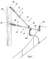
- Figure 5 is a perspective view of an embodiment similar to that of Figure 1 in "push-off" (braced outwards) configuration.
- Figures 1 to 3 show an embodiment of an adjustable cantilever.
- the cantilever of the example has four main parts:
- the unit can be delivered in folded form, or with the parts already assembled. That is to say, with the telescopic tubes already fitted and the connection between the tubes in the folded state, requiring only unfolding and sliding of the telescopic tubes.
- a fixing piece with locking washer allows the position of each telescopic beam to be fixed.
- Ganging scales marked on the proximal portions of the telescopic beam indicate the distance between the post and the overhead line, simplifying installation and adjustment.
- Figure 1 shows an example embodiment of the cantilever forming the subject of the present invention.
- the cantilever -1- consists of a cantilevered main beam -2- and a diagonal beam -3- whose function is to cooperate with the main beam -2- in supporting the securing elements -221-, -222- of the overhead line wires (not shown in the drawing).
- the securing elements comprise a messenger wire support clip -221- and a conductor wire steady carrier -222- in pull-off configuration.
- both elements -221-, -222- are fixed to the main beam -2-, without the possibility of modifying their position.
- the main beam -2- and the diagonal beam -3- are fixed directly to a post -100- with the sole intermediary of the respective insulators -29- and -39- and of hinged post connections -28- and -38- which allow the relative turning of the beams -2- and -3- with respect to the post -100-.
- the main beam -2- is a telescopic beam, which comprises a proximal portion -21- and a distal portion -22-.
- the proximal portion -21- comprises a tube of greater diameter than the tube comprised by the distal portion -22-.
- the distal portion -22- can slide freely inside the proximal portion -21-.
- the messenger wire support clip -221- and the steady carrier -222- are fixed to the distal portion -22-, while the connection between the main beam -2- and the diagonal beam -3- is made by means of a hinged connection -23-, which allows the oblique angle formed between the main beam -2- and the diagonal beam -3- to be varied when the cantilever is adjusted telescopically.
- the diagonal beam -3- could be joined to the distal portion -22- of the horizontal beam -2-, for example in the vicinity of the clip -221-.
- the diagonal beam -3- is telescopic, with a distal portion -32- that slides inside a proximal portion -31-.
- Both the proximal portion -21- of the main beam -2- and the proximal portion -31- of the diagonal beam -3- have, at their ends, the insulators -39-, -29- and hinged connectors -28-, -38- to the post -100-.
- the adjustment device -4- of the hinged main beam -2- of the example shown is designed to provide the cantilever with a continuous range of adjustment positions, and to make adjustment easy and rapid.
- the steady carrier -222- may be, for example, of a known type such as that shown in the drawings, which is provided with a support joined rotatably to the main beam -2- and adjustable in height.
- the adjustment device comprises externally a bushing -4- (in this case a cut bushing) which slides along the proximal portion -21- and has two locking screws -42- and -42'- with locking washers -43- and -43'- which are inserted via a groove -211- in the proximal portion -21- of the beam -2- until they make contact with the distal portion situated inside the proximal portion -21-.
- a bushing -4- in this case a cut bushing
- the bushing -41- in its turn has an aperture -44- which allows the reading of a scale -25-situated on the surface of the proximal portion -21-, which indicates a distance relating to the degree of adjustment of the telescopic device, such as, for example, the distance from the post to the clip -221-, which is an indirect measurement of the offset of the overhead line with respect to the axis of the guide at that point. It is also possible for the scale -25- to indicate the said offset directly.
- Figure 4 shows a cross-section of the adjustment device -4-, in which it can be seen that the tube that forms the distal portion is inserted into the tube that forms the proximal portion -21-.
- the tube that forms the distal portion -22- has at its end a guide plug -228- to facilitate guidance inside the proximal portion -21- and has a drilled part -229- that receives the said locking screws -42- y -42'-.
- the aforementioned bushing -41- can also be seen, as well as the locking washers -43- and -43'-.
- Both the drilled part -229- and the guide plug -226- have drill holes -227-, -226- perpendicular to each other in order to ensure correct fitting.
- Figure 5 shows an embodiment of a cantilever similar to that of Figures 1 to 3 , but in pull-off configuration, for which reason the clip -221- and the steady carrier -222-are in positions which, although fixed, differ from those shown in the aforementioned example of Figures 1 to 3 .
- the other elements of Figure 5 are identical or similar and have been assigned the same numbers, for which reason they will not be explained in greater detail.
- tubes made from an insulating material might be used in order to avoid the use of insulators -29-, -39-.
Landscapes
- Engineering & Computer Science (AREA)
- Mechanical Engineering (AREA)
- Clamps And Clips (AREA)
- Suspension Of Electric Lines Or Cables (AREA)
- Tents Or Canopies (AREA)
- Mutual Connection Of Rods And Tubes (AREA)
Applications Claiming Priority (2)
| Application Number | Priority Date | Filing Date | Title |
|---|---|---|---|
| ES201330512A ES2407804B1 (es) | 2013-04-10 | 2013-04-10 | Mensula para catenaria |
| PCT/ES2014/070270 WO2014167156A1 (es) | 2013-04-10 | 2014-04-07 | Ménsula para catenaria |
Publications (3)
| Publication Number | Publication Date |
|---|---|
| EP2985173A1 true EP2985173A1 (de) | 2016-02-17 |
| EP2985173A4 EP2985173A4 (de) | 2016-11-30 |
| EP2985173B1 EP2985173B1 (de) | 2020-01-08 |
Family
ID=48486077
Family Applications (1)
| Application Number | Title | Priority Date | Filing Date |
|---|---|---|---|
| EP14782767.9A Active EP2985173B1 (de) | 2013-04-10 | 2014-04-07 | Oberleitung ausleger |
Country Status (6)
| Country | Link |
|---|---|
| US (1) | US20160064911A1 (de) |
| EP (1) | EP2985173B1 (de) |
| AU (1) | AU2014252986B2 (de) |
| CA (1) | CA2909026A1 (de) |
| ES (2) | ES2407804B1 (de) |
| WO (1) | WO2014167156A1 (de) |
Cited By (2)
| Publication number | Priority date | Publication date | Assignee | Title |
|---|---|---|---|---|
| WO2019223983A1 (de) * | 2018-05-22 | 2019-11-28 | Siemens Mobility GmbH | Hängerklemme für windschiefe oberleitungen |
| WO2020007524A1 (de) * | 2018-07-05 | 2020-01-09 | Siemens Mobility GmbH | Seitenhalteranordnung und oberleitungsanlage |
Families Citing this family (7)
| Publication number | Priority date | Publication date | Assignee | Title |
|---|---|---|---|---|
| CN109141317B (zh) * | 2018-08-31 | 2023-10-03 | 北京万高众业科技股份有限公司 | 一种碳滑板检测装置、碳滑板检测台及其检测方法 |
| CN109373988B (zh) * | 2018-12-05 | 2023-08-01 | 中铁十二局集团有限公司 | 隧道内接触网无轨施工测量仪器及方法 |
| CN110466393A (zh) * | 2019-09-16 | 2019-11-19 | 中联精工(天津)有限公司 | 高铁用定位支座 |
| CN111591173B (zh) * | 2020-06-04 | 2021-07-23 | 思库轨道交通技术(海南)有限公司 | 铁路接触网智能悬挂固定装置 |
| CN112026593B (zh) * | 2020-07-31 | 2024-07-26 | 智慧支点(北京)科技有限公司 | 接触线组件连接装置及移动接触网系统 |
| CN112026591B (zh) * | 2020-07-31 | 2024-04-09 | 智慧支点(北京)科技有限公司 | 接触线组件连接装置及移动接触网系统 |
| JP7673632B2 (ja) | 2021-12-20 | 2025-05-09 | 中国電力株式会社 | クリート取付構造 |
Family Cites Families (13)
| Publication number | Priority date | Publication date | Assignee | Title |
|---|---|---|---|---|
| GB835227A (en) * | 1955-06-28 | 1960-05-18 | British Insulated Callenders | Improvements in or relating to overhead electric traction systems |
| GB933972A (en) * | 1961-01-25 | 1963-08-14 | British Insulated Callenders | Improvements in or relating to cantilever structures for overhead electric traction systems |
| GB1291842A (en) * | 1969-05-02 | 1972-10-04 | British Insulated Callenders | Improvements in supporting overhead conductors for electric railways |
| GB1291642A (en) * | 1970-01-28 | 1972-10-04 | Macfarlan Smith Ltd | PURIFICATION OF p-AMINOPHENOL |
| JPS57186531A (en) * | 1981-05-13 | 1982-11-17 | Sanwa Tekki Corp | 4-joint link movable bracket |
| GB8333744D0 (en) * | 1983-12-19 | 1984-01-25 | Bicc Plc | Overhead electric traction system |
| GB8502336D0 (en) * | 1985-01-30 | 1985-02-27 | Bicc Plc | Overhead electric traction system |
| IT1230296B (it) * | 1989-07-05 | 1991-10-18 | Salvi & Co Spa A | Struttura di mensola a sbalzo, per il supporto della linea elettrica aerea di contatto, per la trazione elettrica lungo percorsi ferroviari. |
| NO169333C (no) * | 1989-12-20 | 1992-06-10 | Alupro N As | Anordning for opphengning av kjoereledning for skinnegaaende kjoeretoeyer. |
| US7838766B2 (en) * | 2005-11-09 | 2010-11-23 | Paolo M. Dau | Systems and methods for stabilizing cables under heavy loading conditions |
| IT1394380B1 (it) * | 2009-05-25 | 2012-06-15 | Bonomi Eugenio S P A | Mensola di supporto per cavi di linee ferroviarie |
| US9260037B2 (en) * | 2011-01-07 | 2016-02-16 | Impulse Nc Llc | Cantilever assembly |
| SE535969C2 (sv) * | 2011-07-29 | 2013-03-12 | Elek Fierade Lastplatser Sverige Ab | Upphängningsarrangemang för en kontaktledning |
-
2013
- 2013-04-10 ES ES201330512A patent/ES2407804B1/es not_active Expired - Fee Related
-
2014
- 2014-04-07 US US14/784,003 patent/US20160064911A1/en not_active Abandoned
- 2014-04-07 AU AU2014252986A patent/AU2014252986B2/en not_active Ceased
- 2014-04-07 CA CA2909026A patent/CA2909026A1/en not_active Abandoned
- 2014-04-07 ES ES14782767T patent/ES2780906T3/es active Active
- 2014-04-07 EP EP14782767.9A patent/EP2985173B1/de active Active
- 2014-04-07 WO PCT/ES2014/070270 patent/WO2014167156A1/es not_active Ceased
Cited By (2)
| Publication number | Priority date | Publication date | Assignee | Title |
|---|---|---|---|---|
| WO2019223983A1 (de) * | 2018-05-22 | 2019-11-28 | Siemens Mobility GmbH | Hängerklemme für windschiefe oberleitungen |
| WO2020007524A1 (de) * | 2018-07-05 | 2020-01-09 | Siemens Mobility GmbH | Seitenhalteranordnung und oberleitungsanlage |
Also Published As
| Publication number | Publication date |
|---|---|
| AU2014252986A1 (en) | 2015-11-05 |
| EP2985173B1 (de) | 2020-01-08 |
| AU2014252986B2 (en) | 2017-11-02 |
| CA2909026A1 (en) | 2014-10-16 |
| US20160064911A1 (en) | 2016-03-03 |
| WO2014167156A1 (es) | 2014-10-16 |
| ES2407804A1 (es) | 2013-06-14 |
| ES2407804B1 (es) | 2013-12-03 |
| EP2985173A4 (de) | 2016-11-30 |
| ES2780906T3 (es) | 2020-08-27 |
Similar Documents
| Publication | Publication Date | Title |
|---|---|---|
| AU2014252986B2 (en) | Cantilever for overhead contact line | |
| KR101707005B1 (ko) | 철도, 트롤리 및 지하철 라인의 라이브 케이블을 지지하기 위한 캔틸레버 | |
| CN108123400A (zh) | 绝缘操作杆辅助装置 | |
| JP5213905B2 (ja) | 電線弛度測定方法および装置 | |
| US9117574B2 (en) | Adjustable double insulator cover for electrical distribution systems | |
| US8794580B1 (en) | Adjustable mounting bracket | |
| CN106099752B (zh) | 一种适用于更换地线的放线装置 | |
| CN208959174U (zh) | 一种铁塔工程施工安全装置 | |
| KR100904061B1 (ko) | 송전선 고정애자형 접속대 | |
| KR101977188B1 (ko) | 통신 케이블용 선통기 | |
| KR102956576B1 (ko) | 길이 조절이 가능한 배전선로용 완철 | |
| KR102956577B1 (ko) | 조립 가능한 배전선로용 완철 | |
| KR102585361B1 (ko) | 간접활선용 전주의 쇄클 연결장치 | |
| CN219978366U (zh) | 多分裂高压输电线盆式绝缘子检测装置夹持机构 | |
| ES2332351T3 (es) | Pluma oscilante para instalaciones de catenaria. | |
| JP3212404U (ja) | 吊架線支持替工具 | |
| KR20160113770A (ko) | 전차선로 조절장치 | |
| CN221408270U (zh) | 一种可调式街码 | |
| KR102799472B1 (ko) | 송전 특고압선의 철탑 고정용 홀더 | |
| CN113991530B (zh) | 更换绝缘子串用作业滑车的挂点装置 | |
| CN219864411U (zh) | 一种电气施工安全防护装置 | |
| CN209764105U (zh) | 一种棱镜杆的组装式延长杆 | |
| US20250033921A1 (en) | A reel stand | |
| EP3482022B1 (de) | System zur befestigung eines querträgers an mindestens zwei masten in einer maststruktur für die stromübertragung oder -verteilung und verfahren zur befestigung eines solchen querträgers | |
| KR20250021525A (ko) | 조립 가능한 배전선로용 완철 |
Legal Events
| Date | Code | Title | Description |
|---|---|---|---|
| PUAI | Public reference made under article 153(3) epc to a published international application that has entered the european phase |
Free format text: ORIGINAL CODE: 0009012 |
|
| 17P | Request for examination filed |
Effective date: 20151023 |
|
| AK | Designated contracting states |
Kind code of ref document: A1 Designated state(s): AL AT BE BG CH CY CZ DE DK EE ES FI FR GB GR HR HU IE IS IT LI LT LU LV MC MK MT NL NO PL PT RO RS SE SI SK SM TR |
|
| AX | Request for extension of the european patent |
Extension state: BA ME |
|
| DAX | Request for extension of the european patent (deleted) | ||
| A4 | Supplementary search report drawn up and despatched |
Effective date: 20161031 |
|
| RIC1 | Information provided on ipc code assigned before grant |
Ipc: H02G 7/05 20060101ALI20161025BHEP Ipc: B60M 1/20 20060101AFI20161025BHEP |
|
| STAA | Information on the status of an ep patent application or granted ep patent |
Free format text: STATUS: EXAMINATION IS IN PROGRESS |
|
| 17Q | First examination report despatched |
Effective date: 20170706 |
|
| GRAP | Despatch of communication of intention to grant a patent |
Free format text: ORIGINAL CODE: EPIDOSNIGR1 |
|
| STAA | Information on the status of an ep patent application or granted ep patent |
Free format text: STATUS: GRANT OF PATENT IS INTENDED |
|
| INTG | Intention to grant announced |
Effective date: 20190701 |
|
| GRAS | Grant fee paid |
Free format text: ORIGINAL CODE: EPIDOSNIGR3 |
|
| GRAJ | Information related to disapproval of communication of intention to grant by the applicant or resumption of examination proceedings by the epo deleted |
Free format text: ORIGINAL CODE: EPIDOSDIGR1 |
|
| GRAL | Information related to payment of fee for publishing/printing deleted |
Free format text: ORIGINAL CODE: EPIDOSDIGR3 |
|
| STAA | Information on the status of an ep patent application or granted ep patent |
Free format text: STATUS: EXAMINATION IS IN PROGRESS |
|
| INTC | Intention to grant announced (deleted) | ||
| GRAR | Information related to intention to grant a patent recorded |
Free format text: ORIGINAL CODE: EPIDOSNIGR71 |
|
| STAA | Information on the status of an ep patent application or granted ep patent |
Free format text: STATUS: GRANT OF PATENT IS INTENDED |
|
| GRAA | (expected) grant |
Free format text: ORIGINAL CODE: 0009210 |
|
| STAA | Information on the status of an ep patent application or granted ep patent |
Free format text: STATUS: THE PATENT HAS BEEN GRANTED |
|
| AK | Designated contracting states |
Kind code of ref document: B1 Designated state(s): AL AT BE BG CH CY CZ DE DK EE ES FI FR GB GR HR HU IE IS IT LI LT LU LV MC MK MT NL NO PL PT RO RS SE SI SK SM TR |
|
| INTG | Intention to grant announced |
Effective date: 20191129 |
|
| REG | Reference to a national code |
Ref country code: GB Ref legal event code: FG4D |
|
| REG | Reference to a national code |
Ref country code: CH Ref legal event code: EP |
|
| REG | Reference to a national code |
Ref country code: DE Ref legal event code: R096 Ref document number: 602014059720 Country of ref document: DE |
|
| REG | Reference to a national code |
Ref country code: IE Ref legal event code: FG4D |
|
| REG | Reference to a national code |
Ref country code: AT Ref legal event code: REF Ref document number: 1222275 Country of ref document: AT Kind code of ref document: T Effective date: 20200215 |
|
| REG | Reference to a national code |
Ref country code: NL Ref legal event code: MP Effective date: 20200108 |
|
| REG | Reference to a national code |
Ref country code: LT Ref legal event code: MG4D |
|
| PG25 | Lapsed in a contracting state [announced via postgrant information from national office to epo] |
Ref country code: PT Free format text: LAPSE BECAUSE OF FAILURE TO SUBMIT A TRANSLATION OF THE DESCRIPTION OR TO PAY THE FEE WITHIN THE PRESCRIBED TIME-LIMIT Effective date: 20200531 Ref country code: NL Free format text: LAPSE BECAUSE OF FAILURE TO SUBMIT A TRANSLATION OF THE DESCRIPTION OR TO PAY THE FEE WITHIN THE PRESCRIBED TIME-LIMIT Effective date: 20200108 Ref country code: NO Free format text: LAPSE BECAUSE OF FAILURE TO SUBMIT A TRANSLATION OF THE DESCRIPTION OR TO PAY THE FEE WITHIN THE PRESCRIBED TIME-LIMIT Effective date: 20200408 Ref country code: LT Free format text: LAPSE BECAUSE OF FAILURE TO SUBMIT A TRANSLATION OF THE DESCRIPTION OR TO PAY THE FEE WITHIN THE PRESCRIBED TIME-LIMIT Effective date: 20200108 Ref country code: FI Free format text: LAPSE BECAUSE OF FAILURE TO SUBMIT A TRANSLATION OF THE DESCRIPTION OR TO PAY THE FEE WITHIN THE PRESCRIBED TIME-LIMIT Effective date: 20200108 Ref country code: RS Free format text: LAPSE BECAUSE OF FAILURE TO SUBMIT A TRANSLATION OF THE DESCRIPTION OR TO PAY THE FEE WITHIN THE PRESCRIBED TIME-LIMIT Effective date: 20200108 |
|
| REG | Reference to a national code |
Ref country code: ES Ref legal event code: FG2A Ref document number: 2780906 Country of ref document: ES Kind code of ref document: T3 Effective date: 20200827 |
|
| PG25 | Lapsed in a contracting state [announced via postgrant information from national office to epo] |
Ref country code: LV Free format text: LAPSE BECAUSE OF FAILURE TO SUBMIT A TRANSLATION OF THE DESCRIPTION OR TO PAY THE FEE WITHIN THE PRESCRIBED TIME-LIMIT Effective date: 20200108 Ref country code: IS Free format text: LAPSE BECAUSE OF FAILURE TO SUBMIT A TRANSLATION OF THE DESCRIPTION OR TO PAY THE FEE WITHIN THE PRESCRIBED TIME-LIMIT Effective date: 20200508 Ref country code: SE Free format text: LAPSE BECAUSE OF FAILURE TO SUBMIT A TRANSLATION OF THE DESCRIPTION OR TO PAY THE FEE WITHIN THE PRESCRIBED TIME-LIMIT Effective date: 20200108 Ref country code: HR Free format text: LAPSE BECAUSE OF FAILURE TO SUBMIT A TRANSLATION OF THE DESCRIPTION OR TO PAY THE FEE WITHIN THE PRESCRIBED TIME-LIMIT Effective date: 20200108 Ref country code: GR Free format text: LAPSE BECAUSE OF FAILURE TO SUBMIT A TRANSLATION OF THE DESCRIPTION OR TO PAY THE FEE WITHIN THE PRESCRIBED TIME-LIMIT Effective date: 20200409 Ref country code: BG Free format text: LAPSE BECAUSE OF FAILURE TO SUBMIT A TRANSLATION OF THE DESCRIPTION OR TO PAY THE FEE WITHIN THE PRESCRIBED TIME-LIMIT Effective date: 20200408 |
|
| REG | Reference to a national code |
Ref country code: DE Ref legal event code: R097 Ref document number: 602014059720 Country of ref document: DE |
|
| PG25 | Lapsed in a contracting state [announced via postgrant information from national office to epo] |
Ref country code: EE Free format text: LAPSE BECAUSE OF FAILURE TO SUBMIT A TRANSLATION OF THE DESCRIPTION OR TO PAY THE FEE WITHIN THE PRESCRIBED TIME-LIMIT Effective date: 20200108 Ref country code: SM Free format text: LAPSE BECAUSE OF FAILURE TO SUBMIT A TRANSLATION OF THE DESCRIPTION OR TO PAY THE FEE WITHIN THE PRESCRIBED TIME-LIMIT Effective date: 20200108 Ref country code: RO Free format text: LAPSE BECAUSE OF FAILURE TO SUBMIT A TRANSLATION OF THE DESCRIPTION OR TO PAY THE FEE WITHIN THE PRESCRIBED TIME-LIMIT Effective date: 20200108 Ref country code: CZ Free format text: LAPSE BECAUSE OF FAILURE TO SUBMIT A TRANSLATION OF THE DESCRIPTION OR TO PAY THE FEE WITHIN THE PRESCRIBED TIME-LIMIT Effective date: 20200108 Ref country code: SK Free format text: LAPSE BECAUSE OF FAILURE TO SUBMIT A TRANSLATION OF THE DESCRIPTION OR TO PAY THE FEE WITHIN THE PRESCRIBED TIME-LIMIT Effective date: 20200108 Ref country code: DK Free format text: LAPSE BECAUSE OF FAILURE TO SUBMIT A TRANSLATION OF THE DESCRIPTION OR TO PAY THE FEE WITHIN THE PRESCRIBED TIME-LIMIT Effective date: 20200108 |
|
| REG | Reference to a national code |
Ref country code: DE Ref legal event code: R119 Ref document number: 602014059720 Country of ref document: DE |
|
| PLBE | No opposition filed within time limit |
Free format text: ORIGINAL CODE: 0009261 |
|
| STAA | Information on the status of an ep patent application or granted ep patent |
Free format text: STATUS: NO OPPOSITION FILED WITHIN TIME LIMIT |
|
| REG | Reference to a national code |
Ref country code: AT Ref legal event code: MK05 Ref document number: 1222275 Country of ref document: AT Kind code of ref document: T Effective date: 20200108 |
|
| PG25 | Lapsed in a contracting state [announced via postgrant information from national office to epo] |
Ref country code: MC Free format text: LAPSE BECAUSE OF FAILURE TO SUBMIT A TRANSLATION OF THE DESCRIPTION OR TO PAY THE FEE WITHIN THE PRESCRIBED TIME-LIMIT Effective date: 20200108 |
|
| REG | Reference to a national code |
Ref country code: CH Ref legal event code: PL |
|
| 26N | No opposition filed |
Effective date: 20201009 |
|
| PG25 | Lapsed in a contracting state [announced via postgrant information from national office to epo] |
Ref country code: DE Free format text: LAPSE BECAUSE OF NON-PAYMENT OF DUE FEES Effective date: 20201103 Ref country code: LI Free format text: LAPSE BECAUSE OF NON-PAYMENT OF DUE FEES Effective date: 20200430 Ref country code: FR Free format text: LAPSE BECAUSE OF NON-PAYMENT OF DUE FEES Effective date: 20200430 Ref country code: LU Free format text: LAPSE BECAUSE OF NON-PAYMENT OF DUE FEES Effective date: 20200407 Ref country code: IT Free format text: LAPSE BECAUSE OF FAILURE TO SUBMIT A TRANSLATION OF THE DESCRIPTION OR TO PAY THE FEE WITHIN THE PRESCRIBED TIME-LIMIT Effective date: 20200108 Ref country code: CH Free format text: LAPSE BECAUSE OF NON-PAYMENT OF DUE FEES Effective date: 20200430 Ref country code: AT Free format text: LAPSE BECAUSE OF FAILURE TO SUBMIT A TRANSLATION OF THE DESCRIPTION OR TO PAY THE FEE WITHIN THE PRESCRIBED TIME-LIMIT Effective date: 20200108 |
|
| REG | Reference to a national code |
Ref country code: BE Ref legal event code: MM Effective date: 20200430 |
|
| PG25 | Lapsed in a contracting state [announced via postgrant information from national office to epo] |
Ref country code: SI Free format text: LAPSE BECAUSE OF FAILURE TO SUBMIT A TRANSLATION OF THE DESCRIPTION OR TO PAY THE FEE WITHIN THE PRESCRIBED TIME-LIMIT Effective date: 20200108 Ref country code: PL Free format text: LAPSE BECAUSE OF FAILURE TO SUBMIT A TRANSLATION OF THE DESCRIPTION OR TO PAY THE FEE WITHIN THE PRESCRIBED TIME-LIMIT Effective date: 20200108 Ref country code: BE Free format text: LAPSE BECAUSE OF NON-PAYMENT OF DUE FEES Effective date: 20200430 |
|
| GBPC | Gb: european patent ceased through non-payment of renewal fee |
Effective date: 20200408 |
|
| PG25 | Lapsed in a contracting state [announced via postgrant information from national office to epo] |
Ref country code: IE Free format text: LAPSE BECAUSE OF NON-PAYMENT OF DUE FEES Effective date: 20200407 Ref country code: GB Free format text: LAPSE BECAUSE OF NON-PAYMENT OF DUE FEES Effective date: 20200408 |
|
| REG | Reference to a national code |
Ref country code: ES Ref legal event code: PC2A Owner name: MOSDORFER UPRESA RAIL, S.A. Effective date: 20220530 |
|
| PG25 | Lapsed in a contracting state [announced via postgrant information from national office to epo] |
Ref country code: TR Free format text: LAPSE BECAUSE OF FAILURE TO SUBMIT A TRANSLATION OF THE DESCRIPTION OR TO PAY THE FEE WITHIN THE PRESCRIBED TIME-LIMIT Effective date: 20200108 Ref country code: MT Free format text: LAPSE BECAUSE OF FAILURE TO SUBMIT A TRANSLATION OF THE DESCRIPTION OR TO PAY THE FEE WITHIN THE PRESCRIBED TIME-LIMIT Effective date: 20200108 Ref country code: CY Free format text: LAPSE BECAUSE OF FAILURE TO SUBMIT A TRANSLATION OF THE DESCRIPTION OR TO PAY THE FEE WITHIN THE PRESCRIBED TIME-LIMIT Effective date: 20200108 |
|
| PG25 | Lapsed in a contracting state [announced via postgrant information from national office to epo] |
Ref country code: MK Free format text: LAPSE BECAUSE OF FAILURE TO SUBMIT A TRANSLATION OF THE DESCRIPTION OR TO PAY THE FEE WITHIN THE PRESCRIBED TIME-LIMIT Effective date: 20200108 Ref country code: AL Free format text: LAPSE BECAUSE OF FAILURE TO SUBMIT A TRANSLATION OF THE DESCRIPTION OR TO PAY THE FEE WITHIN THE PRESCRIBED TIME-LIMIT Effective date: 20200108 |
|
| PGFP | Annual fee paid to national office [announced via postgrant information from national office to epo] |
Ref country code: ES Payment date: 20250505 Year of fee payment: 12 |