EP2985189A1 - Réseau de bord pour un véhicule, en particulier véhicule industriel - Google Patents
Réseau de bord pour un véhicule, en particulier véhicule industriel Download PDFInfo
- Publication number
- EP2985189A1 EP2985189A1 EP15001573.3A EP15001573A EP2985189A1 EP 2985189 A1 EP2985189 A1 EP 2985189A1 EP 15001573 A EP15001573 A EP 15001573A EP 2985189 A1 EP2985189 A1 EP 2985189A1
- Authority
- EP
- European Patent Office
- Prior art keywords
- electrical system
- voltage
- vehicle
- voltage converter
- subnetwork
- Prior art date
- Legal status (The legal status is an assumption and is not a legal conclusion. Google has not performed a legal analysis and makes no representation as to the accuracy of the status listed.)
- Granted
Links
Images
Classifications
-
- B—PERFORMING OPERATIONS; TRANSPORTING
- B60—VEHICLES IN GENERAL
- B60R—VEHICLES, VEHICLE FITTINGS, OR VEHICLE PARTS, NOT OTHERWISE PROVIDED FOR
- B60R16/00—Electric or fluid circuits specially adapted for vehicles and not otherwise provided for; Arrangement of elements of electric or fluid circuits specially adapted for vehicles and not otherwise provided for
- B60R16/02—Electric or fluid circuits specially adapted for vehicles and not otherwise provided for; Arrangement of elements of electric or fluid circuits specially adapted for vehicles and not otherwise provided for electric constitutive elements
- B60R16/03—Electric or fluid circuits specially adapted for vehicles and not otherwise provided for; Arrangement of elements of electric or fluid circuits specially adapted for vehicles and not otherwise provided for electric constitutive elements for supply of electrical power to vehicle subsystems or for
Definitions
- the invention relates to a vehicle electrical system for a motor vehicle, in particular for a commercial vehicle, with an interface for connecting a trailer electrical system.
- Low-voltage electrical systems of commercial vehicles may have an interface in order to connect the vehicle electrical system of the commercial vehicle to an electrical system of a trailer coupled to the commercial vehicle.
- a trailer coupled to the commercial vehicle.
- city buses can be connected to a so-called passenger trailer to increase the capacity of the lines at peak times.
- passenger trailers have their own on-board electrical system to power the various electrical consumers of the passenger, such as air conditioning and heating system, lighting systems, etc., with electricity.
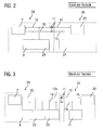
- FIG. 2 illustrating a typical on-board network topology of a vehicle with a trailer.
- the vehicle electrical system 24 has an interface 11 for connecting a trailer electrical system 20.
- An electrical energy store 9, a generator 23 (eg an alternator) and further electrical consumers 7, which form the load resistance of the vehicle electrical system 24, are connected to the vehicle electrical system 24 of the vehicle.
- the consumers 7 of the electrical system are in FIG. 2 as shown in the other figures as a load resistor.
- the consumers 7 of the electrical system 24 are connected in parallel via a supply line 12 and a grounded line 19 to the energy storage 9 and the generator 23.
- the on-board electrical system 20 in turn has one or more electrical consumers 22 and may optionally also have an electrical energy store 21.
- the onboard interface 20 can be electrically connected to the vehicle electrical system 24 via the interface 11.
- the interface 11 may further comprise terminals for further signal lines to control the individual consumers in the trailer. To simplify the illustration are in FIG. 2 these signal lines are not shown.
- FIG. 3 shows another known from the prior art vehicle electrical system 26 which is coupled to a trailer electrical system 20.
- the on-board electrical network 26 differs from the on-board electrical system of FIG. 2 essentially in that in the vehicle electrical system 26 a separate generator 25, z. B. in the form of another alternator, is provided, via which the trailer on-board network 20 is directly supplied.
- the electrical system trailer interface 11 is supplied directly by the additional generator 25 via a supply line 12a. This ensures a balanced charge balance.
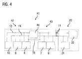
- Vehicle wiring systems are also known from the prior art in which the vehicle electrical system is formed from a plurality of low-voltage sub-network, which are coupled to one another via a DC-DC converter.
- FIG. 4 illustrates the topology of such a vehicle electrical system 41.
- the first low-voltage sub-network 43 in turn comprises an energy storage 9 and a plurality of electrical consumers 7, which form the load resistance of the electrical system 43. For example, a rated voltage of 24 volts may be applied to the first subnetwork.
- a second sub-board network 42 is provided on which, for example, a rated voltage of 48 volts is applied and in which a generator 10, for example a starter-generator, a second energy store 8 and optionally one or more consumers 6, preferably high-power consumers, are arranged.
- the second subnetwork 42 is coupled to the first subnetwork 43 via a DC / DC converter 44, so that the first subnetwork 43 can be supplied with power from the second subnetwork 42 via the DC / DC converter 44.
- a discrete connection 16 of the masses of the two subnetworks may be provided to form a mass connection. It is emphasized that this discrete connection to the mass coupling of the two subnetworks can also be effected by the DC-DC converter 44.
- a disadvantage of such an on-board network topology is the resulting increased load requirement on the DC-DC converter 44, the design of which must be adapted accordingly.
- a further disadvantage is that the additional load of the onboard electrical network 20 can be recognized only indirectly by increased power requirement from the subnetwork 43. It is also disadvantageous that no prioritization with respect to a power supply by the second subnetwork 42 from the vehicle on-board network 43 and the on-board electrical network 20 is possible unless additional switching elements are implemented in the system.
- the state of the onboard electrical system 20 for example, a state of charge of the battery 21 or the power requirement, only by additional introduction of other measuring points, such as voltage and current measuring points, are detected on the battery 21 of the trailer.
- the object of the invention is in particular to provide a vehicle electrical system with at least two coupled via a voltage transformer sub-board networks to which a trailer electrical system is connected and with a controlled power distribution and thus z. B. a prioritization between the vehicle and the on-board network is possible.
- the vehicle electrical system also has a first subnetwork in which a first nominal voltage is applied, and comprises a first energy store and a first load resistor formed by a plurality of consumers.
- the vehicle electrical system also has a second subnetwork, in which a second rated voltage is applied, and includes a generator and a second energy store.
- the first and the second subnetwork are coupled together via a first voltage converter.
- the second rated voltage is preferably higher than the first rated voltage. In the context of the invention, however, there is the possibility that the second rated voltage is the same as the first rated voltage, for example, to couple two 24V vehicle electrical systems with each other.
- a second voltage converter is further provided, wherein the interface for connecting the on-board electrical system via the second voltage converter is coupled to the second subnet.
- the interface for connecting the onboard electrical system is in particular an interface to Supplying the on-board electrical system with electrical energy, ie supplying the on-board electrical system with voltage and current.
- the voltage converter is designed in particular as a controlled or regulated voltage converter.
- the first voltage converter and the second voltage converter can be designed as a DC-DC converter (DC / DC converter).
- the on-board electrical network is thus supplied via the trailer interface via its own voltage converter from the part-board network having the generator.
- a conventional interface for connecting a trailer electrical system can be used with the vehicle on-board network topology according to the invention, so that conventional trailer systems can be connected and operated both with conventional vehicle on-board networks and with the vehicle electrical system according to the invention.
- On-board network topology is that disturbances, such as current ripple or voltage dips, can not spread from the on-board electrical system to the on-board electrical system and vice versa.
- the generator and the second energy store of the second subnetwork as well as the side of the first voltage converter connected to the second subnetwork and the side of the second voltage converter connected to the second subnetwork can be connected in parallel, so that, depending on the control of the voltage converter, optionally energy from the second subnetwork the first sub-network and / or the on-board network can be transferred.
- the first voltage converter and the second voltage converter are designed to convert an applied input voltage of the second subnet to the same output voltage in each case. Furthermore, the first voltage converter and the second voltage converter can be of identical construction.
- a particular advantage ofmaibordnetztopologie invention is thus that the DC-DC converter, which is used in a vehicle electrical system without trailer interface, for the operation of a corresponding electrical system with trailer interface does not need to be adjusted, but only an additional DC-DC converter of the same type can be used, so that a high proportion of identical parts is made possible.
- the first and the second subnet are ground-bound or ground-coupled.
- the second subnet is not designed as a low-voltage board subnet, but as a high-voltage network (rated voltage greater than 60V DC ) of a hybrid or electric vehicle and / or that the two subnets are galvanically separated from each other.
- a control device may be provided to control the operation of the first voltage converter and the second voltage converter.
- a control device is set up to control the first and second DC-DC converters such that energy is transferred from an energy store arranged in the onboard electrical network via the second subnetwork into the first subnetwork, if a state of charge of the energy accumulator in first subnet falls below a predetermined threshold.
- This can be a controlled or regulated energy transfer between the on-board electrical system and the two vehicle sub-board networks take place, so that, for example, a trailer can give the vehicle jump-start.
- control device can be set up to control the first and second DC voltage converters in such a way that energy is transferred from an energy store arranged in the vehicle electrical system via the second voltage converter into the trailer electrical system, if a state of charge of the energy accumulator in the onboard electrical system falls below a predetermined threshold, so that by means of the Vehicle on-board network of trailer energy storage can be specifically loaded and unloaded.
- the second voltage converter may comprise voltage and / or current measuring means on its output side facing the trailer interface.
- This offers the advantage that it is possible to use the (charge) state of the energy storage in the onboard electrical system and to control an energy transfer between the on-board electrical network and the second subnetwork depending on the detected state without the use of additional existing in the onboard electrical system monitoring stations.
- the means for voltage and / or current measurement can here directly on the output side be provided on the second voltage converter or in the line connection between the second voltage converter and the trailer interface.
- a further advantageous embodiment provides that the control device is set up during a stop phase of a start-stop operation of the vehicle to monitor the voltage applied to the interface for connecting the onboard electrical system voltage and to initiate a vehicle start, if the monitored voltage below a predetermined Threshold drops to avoid power failure in the trailer during extended periods of use.
- the generator in the second subsystem can be an electrical machine which is designed for generator operation or recuperation operation and for starting an internal combustion engine of the motor vehicle.
- the generator may be a crankshaft starter generator.
- the second energy store may be a supercapacitor memory or a Li-ion accumulator and may be configured to store electrical charge generated by the generator.
- the first voltage converter and the second voltage converter can be bidirectional, so that energy transfer from the vehicle electrical system to the on-board electrical system and energy transfer from the on-board electrical system to the vehicle electrical system are made possible.
- Another aspect relates to a bus, which is designed for coupling a passenger trailer and having an inventive electrical system, as disclosed herein.
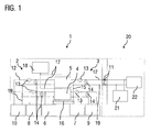
- FIG. 1 schematically illustrates an on-board network topology of a vehicle network from a bus with a passenger trailer.
- the trailer on-board network 20 is in conventional Carried out manner and includes an electrical energy storage and other electrical load 22, which form the load resistance of the electrical system 20 and which are supplied from the power storage 21 in the decoupled state of the trailer from the bus.
- the electrical system 1 of the bus comprises a first sub-network 3, in which a first rated voltage U1, z. B. 24 volts, is applied, and which comprises a first energy storage 9 and a load resistor 7.
- the load resistor 7 is formed by at least one, preferably by a plurality of consumers.
- the consumers in the first subnetwork 3 are preferably operated with a constant supply voltage.
- a sensor 14 for monitoring the voltage in the first subnetwork 3 and a sensor 13 for monitoring the current in the first subnetwork 3 are provided in the first subnetwork 3.
- a second subnet 2 is provided, in which a second mains voltage U2, z. B. 48 volts, is applied and in which a generator 10 is provided.
- a further energy store 8 is further provided, which is designed to store generated by the generator 10 electrical charge.
- the energy store 8 may be formed, for example, as a supercapacitor memory.
- one or more consumers 6 may optionally also be connected, which are preferably high current consumers.
- sensors 13, 14 are provided for current and voltage measurement.
- the solid black lines in FIG. 1 each denote the power lines by means of which the individual components of the vehicle electrical system are connected to each other.
- 12 denotes the electric supply line and the reference numeral 19, the earth-bound line.
- the electrical system 1 further comprises a DC-DC converter (DC / DC converter) 4, which bi-directionally couples the first subnetwork 3 to the second subnetwork 2 in a manner known per se.
- DC-DC converter DC / DC converter
- a second DC-DC converter 5 is provided, via which the second sub-network 2 can be connected to an interface 11 for connecting a trailer electrical system 20.
- the interface 11 is executed in a conventional manner and need not be described in detail. Via the interface 11, the trailer electrical system can be supplied with energy from the vehicle electrical system 1.
- the designated by the reference numeral 15 line is used for grounding the ground-based lines 19th
- the DC-DC converter 4 and 5 are designed to be identical.
- the generator 10, the second energy store 8 and the side of the first voltage converter connected to the second subnet 2 and the side of the second voltage converter 5 connected to the second subnet 2 are connected in parallel.
- the control unit 18 is configured, for example, to monitor the voltage applied to the output side of the second voltage converter 5 and the current flowing there by means of the sensors 13 and 14, wherein the output side is understood to be the side of the second DC-DC converter 5 facing the trailer interface 11. From the detected current and voltage measured values, the state of charge of the energy store 21 of the onboard electrical network 20 can be determined and monitored, if this is connected to the vehicle electrical system 1 via the interface 11.
- the control device 18 is further configured to control the first and second DC-DC converters 4, 5 such that energy is transferred from the energy storage 21 of the on-board electrical system 20 via the second subnetwork 2 into the first subnetwork 3, if a state of charge of the energy storage device 9 in the first subnetwork 3 is below falls a predetermined threshold. Further, during a stop phase of a start-stop operation of the vehicle, the control device is set up to monitor the voltage present at the interface 11 for connection of the onboard electrical network 20 and to initiate a vehicle start if the monitored voltage falls below a predetermined threshold value.
- connection 16 of the masses of the two subnetworks 2, 3, which allows a low-resistance connection between the two subnetworks to form the ground connection of the two subnetworks.
- the dashed line around the connection line 16 is intended to indicate that this line is optional, since such a connection can also be realized directly via the DC / DC converter.
Landscapes
- Engineering & Computer Science (AREA)
- Mechanical Engineering (AREA)
- Electric Propulsion And Braking For Vehicles (AREA)
Priority Applications (1)
| Application Number | Priority Date | Filing Date | Title |
|---|---|---|---|
| PL15001573T PL2985189T3 (pl) | 2014-08-14 | 2015-05-23 | Pokładowa sieć dla pojazdu mechanicznego, w szczególności pojazdu użytkowego |
Applications Claiming Priority (1)
| Application Number | Priority Date | Filing Date | Title |
|---|---|---|---|
| DE102014012154.2A DE102014012154A1 (de) | 2014-08-14 | 2014-08-14 | Bordnetz für ein Kraftfahrzeug, insbesondere für ein Nutzfahrzeug |
Publications (2)
| Publication Number | Publication Date |
|---|---|
| EP2985189A1 true EP2985189A1 (fr) | 2016-02-17 |
| EP2985189B1 EP2985189B1 (fr) | 2018-09-19 |
Family
ID=53365698
Family Applications (1)
| Application Number | Title | Priority Date | Filing Date |
|---|---|---|---|
| EP15001573.3A Active EP2985189B1 (fr) | 2014-08-14 | 2015-05-23 | Réseau de bord pour un véhicule, en particulier véhicule industriel |
Country Status (3)
| Country | Link |
|---|---|
| EP (1) | EP2985189B1 (fr) |
| DE (1) | DE102014012154A1 (fr) |
| PL (1) | PL2985189T3 (fr) |
Cited By (2)
| Publication number | Priority date | Publication date | Assignee | Title |
|---|---|---|---|---|
| CN110325395A (zh) * | 2017-02-27 | 2019-10-11 | 罗伯特·博世有限公司 | 用于运行机动车的设备和方法,机动车 |
| FR3106096A1 (fr) * | 2020-01-15 | 2021-07-16 | Psa Automobiles Sa | Dispositif de distribution d’énergie électrique tout type, pour un véhicule pouvant tracter une remorque |
Families Citing this family (7)
| Publication number | Priority date | Publication date | Assignee | Title |
|---|---|---|---|---|
| JP6211171B2 (ja) | 2014-03-12 | 2017-10-11 | 三菱電機株式会社 | 電源システム |
| DE102016113464A1 (de) * | 2016-07-21 | 2018-01-25 | Dr. Ing. H.C. F. Porsche Aktiengesellschaft | Bordnetz für ein Fahrzeug |
| DE102019125383A1 (de) * | 2019-09-20 | 2021-03-25 | Audi Ag | Kraftfahrzeug mit zwei elektrischen Bordnetzen und einem elektrischen Fremdgeräteanschluss |
| DE102020112836A1 (de) | 2020-05-12 | 2021-11-18 | Bayerische Motoren Werke Aktiengesellschaft | Vorrichtung zum Versorgen eines Anhängers mit elektrischer Energie |
| DE102020112835A1 (de) | 2020-05-12 | 2021-11-18 | Bayerische Motoren Werke Aktiengesellschaft | Vorrichtung zum Versorgen eines Fahrzeugzugs mit elektrischer Energie |
| DE102021209044A1 (de) | 2021-08-18 | 2023-02-23 | Robert Bosch Gesellschaft mit beschränkter Haftung | Fahrzeug mit einem Hochspannungs- und einem Niederspannungssystem |
| DE102023003685A1 (de) | 2023-09-09 | 2025-03-13 | Mercedes-Benz Group AG | Verfahren und Vorrichtung zum elektrischen Verbinden eines Zugfahrzeuges mit einem Anhängerfahrzeug |
Citations (7)
| Publication number | Priority date | Publication date | Assignee | Title |
|---|---|---|---|---|
| US6344985B1 (en) * | 2000-12-05 | 2002-02-05 | Heart Transverter S.A. | Multiple port bi-directional power converter |
| WO2002066293A1 (fr) * | 2001-02-16 | 2002-08-29 | Siemens Aktiengesellschaft | Reseau de bord de vehicule automobile |
| US6507506B1 (en) * | 1999-06-09 | 2003-01-14 | Lear Automotive (Eeds) Spain, S. L. | Dual voltage electrical distribution system |
| EP1422803A1 (fr) * | 2001-08-08 | 2004-05-26 | Lear Automotive (EEDS) Spain, S.L. | Systeme et procede de distribution electrique pour vehicule ayant deux reseaux a differents niveaux de tension |
| WO2009047103A1 (fr) * | 2007-10-09 | 2009-04-16 | Continental Automotive Gmbh | Réseau de bord et son procédé de fonctionnement |
| WO2010002644A1 (fr) * | 2008-07-02 | 2010-01-07 | Jerry Lee Wordsworth | Système de gestion de puissance intelligent |
| US8004242B1 (en) * | 2009-03-13 | 2011-08-23 | PH Ingenuities, LLC | System and method for managing distribution of vehicle power in a multiple battery system |
-
2014
- 2014-08-14 DE DE102014012154.2A patent/DE102014012154A1/de not_active Withdrawn
-
2015
- 2015-05-23 PL PL15001573T patent/PL2985189T3/pl unknown
- 2015-05-23 EP EP15001573.3A patent/EP2985189B1/fr active Active
Patent Citations (7)
| Publication number | Priority date | Publication date | Assignee | Title |
|---|---|---|---|---|
| US6507506B1 (en) * | 1999-06-09 | 2003-01-14 | Lear Automotive (Eeds) Spain, S. L. | Dual voltage electrical distribution system |
| US6344985B1 (en) * | 2000-12-05 | 2002-02-05 | Heart Transverter S.A. | Multiple port bi-directional power converter |
| WO2002066293A1 (fr) * | 2001-02-16 | 2002-08-29 | Siemens Aktiengesellschaft | Reseau de bord de vehicule automobile |
| EP1422803A1 (fr) * | 2001-08-08 | 2004-05-26 | Lear Automotive (EEDS) Spain, S.L. | Systeme et procede de distribution electrique pour vehicule ayant deux reseaux a differents niveaux de tension |
| WO2009047103A1 (fr) * | 2007-10-09 | 2009-04-16 | Continental Automotive Gmbh | Réseau de bord et son procédé de fonctionnement |
| WO2010002644A1 (fr) * | 2008-07-02 | 2010-01-07 | Jerry Lee Wordsworth | Système de gestion de puissance intelligent |
| US8004242B1 (en) * | 2009-03-13 | 2011-08-23 | PH Ingenuities, LLC | System and method for managing distribution of vehicle power in a multiple battery system |
Cited By (3)
| Publication number | Priority date | Publication date | Assignee | Title |
|---|---|---|---|---|
| CN110325395A (zh) * | 2017-02-27 | 2019-10-11 | 罗伯特·博世有限公司 | 用于运行机动车的设备和方法,机动车 |
| CN110325395B (zh) * | 2017-02-27 | 2023-03-14 | 罗伯特·博世有限公司 | 用于运行机动车的设备和方法,机动车 |
| FR3106096A1 (fr) * | 2020-01-15 | 2021-07-16 | Psa Automobiles Sa | Dispositif de distribution d’énergie électrique tout type, pour un véhicule pouvant tracter une remorque |
Also Published As
| Publication number | Publication date |
|---|---|
| PL2985189T3 (pl) | 2019-02-28 |
| EP2985189B1 (fr) | 2018-09-19 |
| DE102014012154A1 (de) | 2016-02-18 |
Similar Documents
| Publication | Publication Date | Title |
|---|---|---|
| EP2985189B1 (fr) | Réseau de bord pour un véhicule, en particulier véhicule industriel | |
| EP2501588B1 (fr) | Réseau de bord, méthode et dispositif de commande du réseau de bord | |
| EP2953227B1 (fr) | Réseau de bord pour un véhicule automobile | |
| EP3027472B1 (fr) | Protection contre les surtensions pour un réseau de bord à multiples tensions | |
| EP2721704B1 (fr) | Dispositif et procédé pour coupler des grilles ayant des tensions différentes | |
| EP3022433B1 (fr) | Disposition d'interrupteur dans un circuit de bord de véhicule à moteur | |
| DE102017009355A1 (de) | Verfahren zum Betreiben von elektrischen Bordnetzen | |
| DE102013200763A1 (de) | System und verfahren für das fahrzeugenergiemanagement | |
| EP3067240B1 (fr) | Procede d'alimentation en tension d'un reseau de bord d'un vehicule automobile | |
| DE102012215542A1 (de) | Schutz- und/oder Diagnoseeinrichtung für Mehrspannungsbordnetz, Mehrspannungsbordnetz und Verfahren zum Betrieb eines Mehrspannungsbordnetzes | |
| DE102013013369A1 (de) | Elektronische Sicherheitsabschaltung für Kraftfahrzeuge | |
| WO2020178233A1 (fr) | Réseau d'énergie pour un véhicule à moteur et procédé de fonctionnement d'un réseau d'énergie pour un véhicule à moteur | |
| DE102012206932A1 (de) | Kraftfahrzeugbordnetz mit wenigstens zwei Teilnetzen | |
| DE102013008420A1 (de) | Antriebseinheit zur Ansteuerung eines Motors | |
| DE102020007868A1 (de) | Verfahren zum Laden eines elektrischen Energiespeichers eines elektrisch angetriebenen Fahrzeugs unter Berücksichtigung einer elektrischen Isolation einer Ladestation, sowie Ladevorrichtung und Fahrzeug | |
| WO2019166148A1 (fr) | Borne de batterie pour réseau de bord de véhicule | |
| DE102016200097A1 (de) | Bordnetz | |
| DE102013014103A1 (de) | Bordnetz für ein Kraftfahrzeug und Verfahren zum Betrieb eines Bordnetzes | |
| EP3380855B1 (fr) | Procédé de détermination d'une information de capacité d'une batterie d'un réseau de bord embarqué dans un véhicule à moteur et relié à un convertisseur cc-cc, et véhicule à moteur | |
| DE102016224618A1 (de) | Fahrzeug-Bordnetz mit hoher Verfügbarkeit | |
| DE102012209453A1 (de) | Kraftfahrzeugbordnetz mit einer elektrischen Maschine und wenigstens zwei Energiespeichern mit unterschiedlichen Ladespannungen sowie Verfahren zum Betreiben desselben | |
| WO2013107560A1 (fr) | Réseau de bord à convertisseur continu-continu, dispositif de commande, et procédé de fonctionnement correspondant | |
| WO2017220233A1 (fr) | Réseau électrique de bord de véhicule à moteur, doté d'au moins deux accumulateurs d'énergie, procédé pour faire fonctionner un réseau électrique de bord et moyens pour sa mise en oeuvre | |
| DE102013002080A1 (de) | Elektrische Konvertierungseinrichtung für ein Elektro- oder Hybridfahrzeug | |
| DE102018210979B4 (de) | Mehrspannungsbatterievorrichtung und Mehrspannungsbordnetz für ein Kraftfahrzeug |
Legal Events
| Date | Code | Title | Description |
|---|---|---|---|
| PUAI | Public reference made under article 153(3) epc to a published international application that has entered the european phase |
Free format text: ORIGINAL CODE: 0009012 |
|
| AK | Designated contracting states |
Kind code of ref document: A1 Designated state(s): AL AT BE BG CH CY CZ DE DK EE ES FI FR GB GR HR HU IE IS IT LI LT LU LV MC MK MT NL NO PL PT RO RS SE SI SK SM TR |
|
| AX | Request for extension of the european patent |
Extension state: BA ME |
|
| 17P | Request for examination filed |
Effective date: 20160808 |
|
| RIC1 | Information provided on ipc code assigned before grant |
Ipc: B60R 16/03 20060101AFI20180308BHEP |
|
| GRAP | Despatch of communication of intention to grant a patent |
Free format text: ORIGINAL CODE: EPIDOSNIGR1 |
|
| STAA | Information on the status of an ep patent application or granted ep patent |
Free format text: STATUS: GRANT OF PATENT IS INTENDED |
|
| INTG | Intention to grant announced |
Effective date: 20180420 |
|
| GRAS | Grant fee paid |
Free format text: ORIGINAL CODE: EPIDOSNIGR3 |
|
| GRAA | (expected) grant |
Free format text: ORIGINAL CODE: 0009210 |
|
| STAA | Information on the status of an ep patent application or granted ep patent |
Free format text: STATUS: THE PATENT HAS BEEN GRANTED |
|
| RIN1 | Information on inventor provided before grant (corrected) |
Inventor name: KRAFT, FERRY Inventor name: KIGIN, ERDOGAN Inventor name: FISCHER, DETLEF Inventor name: PFAU, STEFAN |
|
| AK | Designated contracting states |
Kind code of ref document: B1 Designated state(s): AL AT BE BG CH CY CZ DE DK EE ES FI FR GB GR HR HU IE IS IT LI LT LU LV MC MK MT NL NO PL PT RO RS SE SI SK SM TR |
|
| REG | Reference to a national code |
Ref country code: GB Ref legal event code: FG4D Free format text: NOT ENGLISH |
|
| REG | Reference to a national code |
Ref country code: CH Ref legal event code: EP |
|
| REG | Reference to a national code |
Ref country code: AT Ref legal event code: REF Ref document number: 1042890 Country of ref document: AT Kind code of ref document: T Effective date: 20181015 |
|
| REG | Reference to a national code |
Ref country code: IE Ref legal event code: FG4D Free format text: LANGUAGE OF EP DOCUMENT: GERMAN |
|
| REG | Reference to a national code |
Ref country code: DE Ref legal event code: R096 Ref document number: 502015005910 Country of ref document: DE |
|
| REG | Reference to a national code |
Ref country code: NL Ref legal event code: FP |
|
| REG | Reference to a national code |
Ref country code: SE Ref legal event code: TRGR |
|
| PG25 | Lapsed in a contracting state [announced via postgrant information from national office to epo] |
Ref country code: RS Free format text: LAPSE BECAUSE OF FAILURE TO SUBMIT A TRANSLATION OF THE DESCRIPTION OR TO PAY THE FEE WITHIN THE PRESCRIBED TIME-LIMIT Effective date: 20180919 Ref country code: NO Free format text: LAPSE BECAUSE OF FAILURE TO SUBMIT A TRANSLATION OF THE DESCRIPTION OR TO PAY THE FEE WITHIN THE PRESCRIBED TIME-LIMIT Effective date: 20181219 Ref country code: LT Free format text: LAPSE BECAUSE OF FAILURE TO SUBMIT A TRANSLATION OF THE DESCRIPTION OR TO PAY THE FEE WITHIN THE PRESCRIBED TIME-LIMIT Effective date: 20180919 Ref country code: GR Free format text: LAPSE BECAUSE OF FAILURE TO SUBMIT A TRANSLATION OF THE DESCRIPTION OR TO PAY THE FEE WITHIN THE PRESCRIBED TIME-LIMIT Effective date: 20181220 Ref country code: FI Free format text: LAPSE BECAUSE OF FAILURE TO SUBMIT A TRANSLATION OF THE DESCRIPTION OR TO PAY THE FEE WITHIN THE PRESCRIBED TIME-LIMIT Effective date: 20180919 Ref country code: BG Free format text: LAPSE BECAUSE OF FAILURE TO SUBMIT A TRANSLATION OF THE DESCRIPTION OR TO PAY THE FEE WITHIN THE PRESCRIBED TIME-LIMIT Effective date: 20181219 |
|
| REG | Reference to a national code |
Ref country code: LT Ref legal event code: MG4D |
|
| PG25 | Lapsed in a contracting state [announced via postgrant information from national office to epo] |
Ref country code: LV Free format text: LAPSE BECAUSE OF FAILURE TO SUBMIT A TRANSLATION OF THE DESCRIPTION OR TO PAY THE FEE WITHIN THE PRESCRIBED TIME-LIMIT Effective date: 20180919 Ref country code: AL Free format text: LAPSE BECAUSE OF FAILURE TO SUBMIT A TRANSLATION OF THE DESCRIPTION OR TO PAY THE FEE WITHIN THE PRESCRIBED TIME-LIMIT Effective date: 20180919 Ref country code: HR Free format text: LAPSE BECAUSE OF FAILURE TO SUBMIT A TRANSLATION OF THE DESCRIPTION OR TO PAY THE FEE WITHIN THE PRESCRIBED TIME-LIMIT Effective date: 20180919 |
|
| PG25 | Lapsed in a contracting state [announced via postgrant information from national office to epo] |
Ref country code: ES Free format text: LAPSE BECAUSE OF FAILURE TO SUBMIT A TRANSLATION OF THE DESCRIPTION OR TO PAY THE FEE WITHIN THE PRESCRIBED TIME-LIMIT Effective date: 20180919 Ref country code: IS Free format text: LAPSE BECAUSE OF FAILURE TO SUBMIT A TRANSLATION OF THE DESCRIPTION OR TO PAY THE FEE WITHIN THE PRESCRIBED TIME-LIMIT Effective date: 20190119 Ref country code: RO Free format text: LAPSE BECAUSE OF FAILURE TO SUBMIT A TRANSLATION OF THE DESCRIPTION OR TO PAY THE FEE WITHIN THE PRESCRIBED TIME-LIMIT Effective date: 20180919 Ref country code: CZ Free format text: LAPSE BECAUSE OF FAILURE TO SUBMIT A TRANSLATION OF THE DESCRIPTION OR TO PAY THE FEE WITHIN THE PRESCRIBED TIME-LIMIT Effective date: 20180919 Ref country code: EE Free format text: LAPSE BECAUSE OF FAILURE TO SUBMIT A TRANSLATION OF THE DESCRIPTION OR TO PAY THE FEE WITHIN THE PRESCRIBED TIME-LIMIT Effective date: 20180919 |
|
| PG25 | Lapsed in a contracting state [announced via postgrant information from national office to epo] |
Ref country code: SK Free format text: LAPSE BECAUSE OF FAILURE TO SUBMIT A TRANSLATION OF THE DESCRIPTION OR TO PAY THE FEE WITHIN THE PRESCRIBED TIME-LIMIT Effective date: 20180919 Ref country code: SM Free format text: LAPSE BECAUSE OF FAILURE TO SUBMIT A TRANSLATION OF THE DESCRIPTION OR TO PAY THE FEE WITHIN THE PRESCRIBED TIME-LIMIT Effective date: 20180919 Ref country code: PT Free format text: LAPSE BECAUSE OF FAILURE TO SUBMIT A TRANSLATION OF THE DESCRIPTION OR TO PAY THE FEE WITHIN THE PRESCRIBED TIME-LIMIT Effective date: 20190119 |
|
| REG | Reference to a national code |
Ref country code: DE Ref legal event code: R097 Ref document number: 502015005910 Country of ref document: DE |
|
| RAP2 | Party data changed (patent owner data changed or rights of a patent transferred) |
Owner name: MAN TRUCK & BUS SE |
|
| PLBE | No opposition filed within time limit |
Free format text: ORIGINAL CODE: 0009261 |
|
| STAA | Information on the status of an ep patent application or granted ep patent |
Free format text: STATUS: NO OPPOSITION FILED WITHIN TIME LIMIT |
|
| PG25 | Lapsed in a contracting state [announced via postgrant information from national office to epo] |
Ref country code: DK Free format text: LAPSE BECAUSE OF FAILURE TO SUBMIT A TRANSLATION OF THE DESCRIPTION OR TO PAY THE FEE WITHIN THE PRESCRIBED TIME-LIMIT Effective date: 20180919 |
|
| 26N | No opposition filed |
Effective date: 20190620 |
|
| REG | Reference to a national code |
Ref country code: DE Ref legal event code: R081 Ref document number: 502015005910 Country of ref document: DE Owner name: MAN TRUCK & BUS SE, DE Free format text: FORMER OWNER: MAN TRUCK & BUS AG, 80995 MUENCHEN, DE |
|
| PG25 | Lapsed in a contracting state [announced via postgrant information from national office to epo] |
Ref country code: SI Free format text: LAPSE BECAUSE OF FAILURE TO SUBMIT A TRANSLATION OF THE DESCRIPTION OR TO PAY THE FEE WITHIN THE PRESCRIBED TIME-LIMIT Effective date: 20180919 |
|
| REG | Reference to a national code |
Ref country code: CH Ref legal event code: PL |
|
| GBPC | Gb: european patent ceased through non-payment of renewal fee |
Effective date: 20190523 |
|
| PG25 | Lapsed in a contracting state [announced via postgrant information from national office to epo] |
Ref country code: LI Free format text: LAPSE BECAUSE OF NON-PAYMENT OF DUE FEES Effective date: 20190531 Ref country code: MC Free format text: LAPSE BECAUSE OF FAILURE TO SUBMIT A TRANSLATION OF THE DESCRIPTION OR TO PAY THE FEE WITHIN THE PRESCRIBED TIME-LIMIT Effective date: 20180919 Ref country code: CH Free format text: LAPSE BECAUSE OF NON-PAYMENT OF DUE FEES Effective date: 20190531 |
|
| REG | Reference to a national code |
Ref country code: BE Ref legal event code: MM Effective date: 20190531 |
|
| PG25 | Lapsed in a contracting state [announced via postgrant information from national office to epo] |
Ref country code: LU Free format text: LAPSE BECAUSE OF NON-PAYMENT OF DUE FEES Effective date: 20190523 |
|
| PG25 | Lapsed in a contracting state [announced via postgrant information from national office to epo] |
Ref country code: IE Free format text: LAPSE BECAUSE OF NON-PAYMENT OF DUE FEES Effective date: 20190523 Ref country code: GB Free format text: LAPSE BECAUSE OF NON-PAYMENT OF DUE FEES Effective date: 20190523 |
|
| PG25 | Lapsed in a contracting state [announced via postgrant information from national office to epo] |
Ref country code: BE Free format text: LAPSE BECAUSE OF NON-PAYMENT OF DUE FEES Effective date: 20190531 |
|
| PG25 | Lapsed in a contracting state [announced via postgrant information from national office to epo] |
Ref country code: CY Free format text: LAPSE BECAUSE OF FAILURE TO SUBMIT A TRANSLATION OF THE DESCRIPTION OR TO PAY THE FEE WITHIN THE PRESCRIBED TIME-LIMIT Effective date: 20180919 |
|
| REG | Reference to a national code |
Ref country code: AT Ref legal event code: MM01 Ref document number: 1042890 Country of ref document: AT Kind code of ref document: T Effective date: 20200523 |
|
| PG25 | Lapsed in a contracting state [announced via postgrant information from national office to epo] |
Ref country code: MT Free format text: LAPSE BECAUSE OF FAILURE TO SUBMIT A TRANSLATION OF THE DESCRIPTION OR TO PAY THE FEE WITHIN THE PRESCRIBED TIME-LIMIT Effective date: 20180919 |
|
| PG25 | Lapsed in a contracting state [announced via postgrant information from national office to epo] |
Ref country code: AT Free format text: LAPSE BECAUSE OF NON-PAYMENT OF DUE FEES Effective date: 20200523 |
|
| PG25 | Lapsed in a contracting state [announced via postgrant information from national office to epo] |
Ref country code: MK Free format text: LAPSE BECAUSE OF FAILURE TO SUBMIT A TRANSLATION OF THE DESCRIPTION OR TO PAY THE FEE WITHIN THE PRESCRIBED TIME-LIMIT Effective date: 20180919 |
|
| PGFP | Annual fee paid to national office [announced via postgrant information from national office to epo] |
Ref country code: NL Payment date: 20250526 Year of fee payment: 11 |
|
| PGFP | Annual fee paid to national office [announced via postgrant information from national office to epo] |
Ref country code: PL Payment date: 20250514 Year of fee payment: 11 Ref country code: DE Payment date: 20250528 Year of fee payment: 11 |
|
| PGFP | Annual fee paid to national office [announced via postgrant information from national office to epo] |
Ref country code: HU Payment date: 20250530 Year of fee payment: 11 |
|
| PGFP | Annual fee paid to national office [announced via postgrant information from national office to epo] |
Ref country code: IT Payment date: 20250522 Year of fee payment: 11 |
|
| PGFP | Annual fee paid to national office [announced via postgrant information from national office to epo] |
Ref country code: FR Payment date: 20250526 Year of fee payment: 11 |
|
| PGFP | Annual fee paid to national office [announced via postgrant information from national office to epo] |
Ref country code: TR Payment date: 20250512 Year of fee payment: 11 |
|
| PGFP | Annual fee paid to national office [announced via postgrant information from national office to epo] |
Ref country code: SE Payment date: 20250526 Year of fee payment: 11 |