EP2985241A1 - Installation de stockage d'objets - Google Patents
Installation de stockage d'objets Download PDFInfo
- Publication number
- EP2985241A1 EP2985241A1 EP14405064.8A EP14405064A EP2985241A1 EP 2985241 A1 EP2985241 A1 EP 2985241A1 EP 14405064 A EP14405064 A EP 14405064A EP 2985241 A1 EP2985241 A1 EP 2985241A1
- Authority
- EP
- European Patent Office
- Prior art keywords
- objects
- storage area
- horizontal plane
- storage
- installation according
- Prior art date
- Legal status (The legal status is an assumption and is not a legal conclusion. Google has not performed a legal analysis and makes no representation as to the accuracy of the status listed.)
- Withdrawn
Links
Images
Classifications
-
- B—PERFORMING OPERATIONS; TRANSPORTING
- B65—CONVEYING; PACKING; STORING; HANDLING THIN OR FILAMENTARY MATERIAL
- B65G—TRANSPORT OR STORAGE DEVICES, e.g. CONVEYORS FOR LOADING OR TIPPING, SHOP CONVEYOR SYSTEMS OR PNEUMATIC TUBE CONVEYORS
- B65G1/00—Storing articles, individually or in orderly arrangement, in warehouses or magazines
- B65G1/02—Storage devices
- B65G1/04—Storage devices mechanical
- B65G1/0464—Storage devices mechanical with access from above
-
- B—PERFORMING OPERATIONS; TRANSPORTING
- B29—WORKING OF PLASTICS; WORKING OF SUBSTANCES IN A PLASTIC STATE IN GENERAL
- B29D—PRODUCING PARTICULAR ARTICLES FROM PLASTICS OR FROM SUBSTANCES IN A PLASTIC STATE
- B29D30/00—Producing pneumatic or solid tyres or parts thereof
- B29D30/0016—Handling tyres or parts thereof, e.g. supplying, storing, conveying
-
- B—PERFORMING OPERATIONS; TRANSPORTING
- B29—WORKING OF PLASTICS; WORKING OF SUBSTANCES IN A PLASTIC STATE IN GENERAL
- B29D—PRODUCING PARTICULAR ARTICLES FROM PLASTICS OR FROM SUBSTANCES IN A PLASTIC STATE
- B29D30/00—Producing pneumatic or solid tyres or parts thereof
- B29D30/0016—Handling tyres or parts thereof, e.g. supplying, storing, conveying
- B29D2030/0027—Handling cured tyres, e.g. transferring or storing after vulcanizing
-
- B—PERFORMING OPERATIONS; TRANSPORTING
- B65—CONVEYING; PACKING; STORING; HANDLING THIN OR FILAMENTARY MATERIAL
- B65G—TRANSPORT OR STORAGE DEVICES, e.g. CONVEYORS FOR LOADING OR TIPPING, SHOP CONVEYOR SYSTEMS OR PNEUMATIC TUBE CONVEYORS
- B65G2201/00—Indexing codes relating to handling devices, e.g. conveyors, characterised by the type of product or load being conveyed or handled
- B65G2201/02—Articles
- B65G2201/0273—Tires
Definitions
- the invention relates to a system for storing objects in a storage room.
- the storage room can be located in a building, for example a warehouse, or the storage room is a space allocated outside a building, which is provided for storing objects.
- a building for example a warehouse
- the storage room is a space allocated outside a building, which is provided for storing objects.
- various lift and crane systems with a portal structure are known.
- the available storage space should be used optimally. Therefore, if possible, the objects are stacked on top of each other.
- stackable items can not be stacked arbitrarily high. At a certain height, the pile becomes unstable and threatens to fall over.
- items found at the bottom of the stack may be damaged by the weight of the overlying items.
- the stacking height should typically not be more than 2 m, otherwise the lower tires will be squeezed and thereby damaged by the weight of the overlying tires.
- containers such. B. Boxes often can not be stacked at any height without damaging them. Due to the limitation of the stack height, for example, in high warehouses or outdoors, the available storage space is not optimally utilized. In part, attempts are being made to circumvent this with structural measures. For example, by building multi-storey warehouses. Such solutions are very complex and expensive and make storage difficult.
- the object of the invention is to provide a plant belonging to the aforementioned technical field, which optimally utilizes an existing storage space for stackable objects.
- an installation according to the invention comprises a portal structure with a first Portal bridge in a first storage area, which is movable in a first horizontal plane in a first horizontal direction. At least a first carriage for transporting objects along the first gantry bridge is movably arranged on the first gantry bridge.
- the gantry structure also includes at least one second gantry bridge in a second storage area, which is movable in a second horizontal direction in a second horizontal plane independently of the first gantry bridge.
- the second horizontal plane is higher than the first horizontal plane.
- the second horizontal direction preferably corresponds to the first horizontal direction, but this is not mandatory.
- At the second portal bridge at least a second carriage for transporting objects along the second portal bridge is arranged movable.
- a second carriage for transporting objects along the second portal bridge is arranged movable.
- an intermediate floor is attached to the portal structure, which separates the first and the second storage area and is suitable for receiving objects.
- the portal structure has a second gantry bridge over the first gantry bridge, a second storage area can be opened.
- the free space above a stack of objects is also usable.
- the intermediate floor is attached directly to the portal structure, no additional structural measures to the warehouse are necessary.
- the second moveable gantry bridge allows faster moving of objects into the warehouse or from the warehouse.
- the plant according to the invention differs from multi-storey facilities with an intermediate floor firmly connected to the building.
- Such systems essentially consist of mezzanines of the building, on each of which a system with a portal structure is installed. At least part of the portal structure stands on the mezzanine. This, in contrast to the inventive system in which the intermediate floor is attached directly to the portal structure and which does not require a multi-storey building.
- the inventive system may be formed two-storey, so have two superimposed gantry bridges and an intermediate floor. But it can also be designed in three stories, so three superimposed gantry bridges and two Have intermediate floors. Furthermore, the inventive system may also have more than three floors.
- One, two or more portal bridges may be present on one or both floors.
- the stored items may be, for example, containers such as boxes or boxes or other particular stackable items such.
- the items can be stored in the plant, flexibly removed from this or moved in this from one place to another.
- a first gripper is mounted on the first carriage and a second gripper on the second carriage in such a manner that the first gripper can grasp objects located in the first storage area, in particular on a ground floor, and the second gripper, in turn, can grasp objects can be in the second storage area, in particular so on the false floor, can take.
- the respective embodiment of the gripper is adapted to the objects to be stored. Grippers have the advantage that they can, depending on the subject, this without aids, such as a support frame, take.
- hooks can cooperate, for example, with carrying racks on which the articles are stored,
- the grippers are designed in such a way that they can remove a predetermined number of objects from a stack of objects or supply a predetermined number of objects to them. This has the advantage that multiple items can be moved at the same time. This speeds up the feeding and discharging of objects.
- grippers are conceivable that can only move one object at a time. This variant may also be conditioned by the nature of the object.
- a device which can move the articles between the storage areas.
- a device may in particular be a lift.
- This lift can simultaneously move one or more objects from a designated exchange point of a storage area to a designated exchange point of the other storage area.
- the respective grippers or transport elements in the storage areas can then in turn move objects to or from these replacement points. This allows the direct and therefore quick and easy exchange of objects between the storage areas. This allows the different storage areas as a whole to be better organized.
- such replacement may be with an external device, for example, a mobile device in the form of a forklift.
- the first and / or the second gripper can be movable in such a way that they can reach into the respective other storage area and thus move objects from one storage area into the other storage area .
- the second gripper for example, can be moved so far downwards in the vertical direction that it can directly grasp objects deposited at the corresponding location of the first storage area.
- an additional device may perform the same function.
- At least one article feed and at least one article removal are present in each storage area.
- the article feed and the article removal can be the same device, or two different devices are provided for this purpose.
- This has the advantage that items can be more efficiently supplied to the storage areas and removed from them.
- an automated organization of the Storage room allows. For example, the number and type of items in stock can be recorded. The number of article feeds as well as article transfers can be adapted to the intended fluctuations in the corresponding storage areas.
- external devices such as forklifts, may discharge articles to and from the bearing.
- the false floor is a lightweight construction, for example a grid-like construction.
- One possible embodiment consists of a lamellar checker plate. This has the advantage that the overall weight of the system is reduced by the light embodiment.
- the embodiment of the false floor is to be adapted.
- the intermediate floor is provided with a fire protection system, in particular a sprinkler system.
- a fire protection system in particular a sprinkler system.
- fire protection may be incorporated in other parts of the portal structure or storage areas. Depending on the situation, you can even do without it altogether.
- the intermediate floor is attached to the portal structure such that the portal structure is stabilized thereby.
- the intermediate bottom not only serves as a storage surface of the objects, but serves the Portal structure also as a strut, which gives the whole construction an additional grip.
- the intermediate floor does not serve - as a mezzanine floor of a building - as the basis for the second (upper) portal bridge.
- the false floor depending on the object to be stored, be very easily constructed.
- the stability of the portal structure is then ensured by other elements of the portal structure.
- the system comprises a plurality of supporting pillars extending in the vertical direction, to which longitudinal beams for displaceable mounting of the portal bridges as well as the intermediate floor are fastened and mounted.
- the longitudinal beams are mounted both for the first gantry bridge in the first storage area and for the second gantry bridge in the second storage area on the same pillars. This allows a particularly simple construction and a good use of space.
- separate pillars are available for the first gantry bridge and the second gantry bridge.
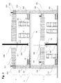
- the FIG. 1 shows a schematic side view of an inventive system with a portal structure for storing objects.
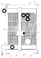
- the FIG. 2 FIG. 3 illustrates a schematic plan view of the second storage area of the installation according to the invention.
- the objects are tires 50 which are stacked tower-like, but an analogous embodiment is also suitable for managing a storage for other objects, e.g. As boxes or other containers, usable.
- the tires 50 are stacked on top of each other so that hollow cylindrical stacks 51 are formed. This results in a vertically oriented stacking axis 52.
- the maximum stacking height of the tires 50 is approximately 2.2 meters. If the tires 50 are stacked higher, the bottommost tires 50 may be damaged by the weight of the upper tires 50.
- a first gantry bridge 101 In a first storage area 1, in a first horizontal plane 100, there is a first gantry bridge 101, which is supported at its ends on a respective longitudinal beam 102 and 103.
- the first gantry bridge 101 is at a right angle to the longitudinal beams 102 and 103.
- the longitudinal beams 102 and 103 are in turn supported at their ends on buttresses 204, 205, 206 and 207 (see also FIG. 2 ).
- the portal bridge 101 is displaceable along the longitudinal beams 102 and 103.
- the portal bridge 101 has a cuboid cross section with the approximate dimension 0.8 mx 1.0 m.
- the length of the portal bridge 101 is about 20 m.
- the pillars 204, 205, 206 and 207 are about 0.4 m thick.
- a horizontally movable first slide 108 is attached to which a first gripper 109 is present.
- the gripper 109 shown here essentially consists of an actuating device 110, which can vertically move a rod 111 up and down along a longitudinal axis 112.
- actuating device 110 can vertically move a rod 111 up and down along a longitudinal axis 112.
- At a lower end of the rod 111 are horizontally extendable fingers 113 attached, which can slide between stacked tires 50.
- the gripper 109 can displace one or more hoops 50 at the same time by moving the bar 111 with the fingers 113 together along the stacking axis 52 into the interior of the gripper Stack 51 is performed.
- the fingers 113 are extended and pushed between two tires 50.
- tires 50 which are located above the fingers 113 are lifted off the stack 51.
- tires 50 can also be deposited on a stack 51.
- Other grippers which are particularly suitable for the handling of boxes, go for example from the EP 1 620 332 B1 (Güdel Group AG).
- a second gantry bridge 201 In a second storage area 2 is located in a second horizontal plane 200, a second gantry bridge 201, which in turn is supported at the ends of longitudinal beams 202 and 203.
- the longitudinal beams 202 and 203 of the second bearing plane 2 are also supported by the two supporting pillars 204, 205, 206 and 207 at their ends (see also FIG. 2 ).
- a second carriage 208 is attached to the second gantry bridge 201, on which there is a second gripper 209 with a second actuating device 210, with a second rod 211 and fingers 213.
- the dimensions and embodiment of the second gantry bridge 201, the second carriage 208, and the second gripper 209 of the second storage area 2 essentially correspond to those of the first storage area 1.
- the second storage area 2 is separated from the underlying first storage area 1 by a lying in a third horizontal plane 3, rectangular intermediate bottom 30.
- the intermediate floor 30 is attached to the pillars 204, 205, 206 and 207 of the longitudinal beams 102, 103 of the first gantry bridge 101 and the longitudinal beams 202 and 203 of the second gantry bridge 201.
- This intermediate floor 30 is lattice-like, consisting of a lamellar checker plate.
- Tires 50 in the second storage area 2 are stored on this intermediate floor 30. The gripping, moving and depositing of the tires 50 in the second storage area 2 takes place analogously to the first storage area 1.
- the intermediate floor 30 is attached at the corners to the second support pillars 204, 205, 206 and 207 of the longitudinal beams 202 and 203 of the second portal bridge 201 is, it increases the stability of the portal structure.
- the intermediate floor 30 is located at a height of about 5.0 m. With a maximum pile height of 2.2 m each, the overall height of the two-story portal structure of approx. 10.0 m, you can thus install a warehouse with an interior height of 10.5 m or more. With a suitable structure, loads of 1500 kg can be lifted. In the longitudinal and transverse directions, speeds of 300 m / min and accelerations of 6 m / s 2 can be achieved, in the vertical direction a speed of 160 m / min can be achieved with maximum accelerations of 10 m / s 2 .
- tires 50 can be displaced into or out of the first, as well as the second storage area 1 and 2, there are one item supply per each level and one item removal per level. They are formed by two conveyor belts 121, 122 in the first storage area 1 and two conveyor belts 221, 222 in the second storage area, which extend parallel to the longitudinal beams 102, 103, 202, 203 and extend into the respective storage areas 1 and 2.
- the grippers 109 and 209 can then take the tires 50 from the corresponding conveyor belt 121, 122, 221, 222 or deposit them, in particular at a certain exchange point in their storage area 1 and 2, depending on whether a tire 50 or a stack 51 is supplied or should be removed.
- a conveyor belt 121, 122, 221, 222 either serve only as article feed or article removal, or a conveyor belt 121, 122, 221, 222 can fulfill both tasks.
- the number of conveyor belts for the supply and removal of tires per storage area 1 and 2 may vary from plant to plant, depending on how often tire 50 in respectively from the respective storage area 1 and 2 are discharged zurespektive.
- an opening 31 in the intermediate bottom 30 in the form of a sufficiently large-scale breakthrough tires 50 can be moved between the first and the second storage area 1 and 2.
- the size and position of the opening 31 are selected so that, for example, the second gripper 209 can move tires 50 through the opening 31.
- the length of the second bar 210 of the second gripper 209 is dimensioned such that the second gripper 209 can reach into the first storage area 1 from the second storage area 2 through the opening 31 and move the tire 50 into or away from the first storage area 1.
- the rod 210 is formed telescopically in a conventional manner.
- an additional lift or crane system executes the exchange between the first and the second storage area 1, 2.
- a fire protection system can be installed in the intermediate floor 30 in the intermediate floor 30 .
- a sprinkler system can be mounted on an underside of the intermediate floor, which can act directly on the underlying tires 50 in the first storage area 1 in the event of a fire.
- the grippers mentioned in the description engage in the interior of the tire stack.
- other types of grippers can also be used.
- grippers are conceivable which grip the tires from the outside.
- the fingers can be moved differently: for example, pneumatically, hydraulically or with the help of an electric motor.
- the embodiment of the gripper is adapted to the respective objects.
- the first gripper can reach into the second storage area or that both grippers can reach into the respective other storage area.
- objects can be exchanged between the two storage areas with the aid of a crane or lift system.
- this crane-view lift system can also use an opening in the intermediate floor for moving the objects, or it is arranged laterally of the false floor.
- the embodiment of the rectangular false floor may vary.
- it is a lightweight construction which is secured at the corners to the buttresses of the second storage area. So that the weight of the false floor can be reduced, too Recesses in the intermediate floor conceivable, the intermediate floor can be designed for example as a perforated plate.
- the lightweight construction must be strong enough to carry the weight of a full storage area.
- a gantry bridge with a carriage and a gripper is provided per storage area.
- several grippers per storage area may also be present. These additional grippers can either be mounted on the same slide or on an additional slide, on the same gantry bridge or on an additional gantry bridge. The additional grippers can have access to different stacks or to the same stacks in one storage area.
- fire protection systems which are attached to the underside of the false floor.
- Which type of fire retardant is used is determined primarily by the items to be stored. It may be, for example, water, dust or dry ice (CO 2 ).
- additional security elements may be attached to the false floor. For example, it is conceivable to install a warning system in the false floor, which detects when a person is entering a danger zone of a storage area. The system can then be stopped automatically.
- the same pillars are used for the first horizontal plane and the second horizontal plane. It is also possible in principle to support the longitudinal beams of two or more horizontal planes (as well as the intermediate floors) at different buttresses. Furthermore, depending on the areal extent of the storage areas more than four pillars are used. For example, the side members of the side members at regular intervals support pillars are provided, on which the side members are mounted.
- the embodiment is an inventive system for tires. Analogous systems are possible which store different types of objects, stackable and non-stackable.
Landscapes
- Engineering & Computer Science (AREA)
- Mechanical Engineering (AREA)
- Warehouses Or Storage Devices (AREA)
Priority Applications (1)
| Application Number | Priority Date | Filing Date | Title |
|---|---|---|---|
| EP14405064.8A EP2985241A1 (fr) | 2014-08-15 | 2014-08-15 | Installation de stockage d'objets |
Applications Claiming Priority (1)
| Application Number | Priority Date | Filing Date | Title |
|---|---|---|---|
| EP14405064.8A EP2985241A1 (fr) | 2014-08-15 | 2014-08-15 | Installation de stockage d'objets |
Publications (1)
| Publication Number | Publication Date |
|---|---|
| EP2985241A1 true EP2985241A1 (fr) | 2016-02-17 |
Family
ID=51485542
Family Applications (1)
| Application Number | Title | Priority Date | Filing Date |
|---|---|---|---|
| EP14405064.8A Withdrawn EP2985241A1 (fr) | 2014-08-15 | 2014-08-15 | Installation de stockage d'objets |
Country Status (1)
| Country | Link |
|---|---|
| EP (1) | EP2985241A1 (fr) |
Citations (7)
| Publication number | Priority date | Publication date | Assignee | Title |
|---|---|---|---|---|
| JPS57124503U (fr) * | 1981-01-30 | 1982-08-03 | ||
| JPH10147407A (ja) * | 1996-11-20 | 1998-06-02 | Ishikawajima Harima Heavy Ind Co Ltd | コンテナ立体貯蔵装置 |
| JP2001031219A (ja) * | 1999-07-19 | 2001-02-06 | Bridgestone Corp | タイヤの中間保管方法及び中間保管システム |
| EP1489026A1 (fr) * | 2003-06-19 | 2004-12-22 | Hankook Tire Co., Ltd. | Système automatique pour faire entrer ou sortir de palettes dans un depot |
| JP2008174374A (ja) * | 2007-01-22 | 2008-07-31 | Nippon Yuusen Kk | 立体格納庫およびそれによるコンテナの荷役方法 |
| EP1620332B1 (fr) | 2003-04-14 | 2012-10-10 | Güdel Group AG | Dispositif et procede d'exploitation d'un entrepot |
| FR3007310A1 (fr) * | 2013-06-21 | 2014-12-26 | Jean Pierre Solignac | Unite de production de produits manufactures comprenant un magasin automotique apte a etre associe a l execution de taches d un processus de fabrication |
-
2014
- 2014-08-15 EP EP14405064.8A patent/EP2985241A1/fr not_active Withdrawn
Patent Citations (7)
| Publication number | Priority date | Publication date | Assignee | Title |
|---|---|---|---|---|
| JPS57124503U (fr) * | 1981-01-30 | 1982-08-03 | ||
| JPH10147407A (ja) * | 1996-11-20 | 1998-06-02 | Ishikawajima Harima Heavy Ind Co Ltd | コンテナ立体貯蔵装置 |
| JP2001031219A (ja) * | 1999-07-19 | 2001-02-06 | Bridgestone Corp | タイヤの中間保管方法及び中間保管システム |
| EP1620332B1 (fr) | 2003-04-14 | 2012-10-10 | Güdel Group AG | Dispositif et procede d'exploitation d'un entrepot |
| EP1489026A1 (fr) * | 2003-06-19 | 2004-12-22 | Hankook Tire Co., Ltd. | Système automatique pour faire entrer ou sortir de palettes dans un depot |
| JP2008174374A (ja) * | 2007-01-22 | 2008-07-31 | Nippon Yuusen Kk | 立体格納庫およびそれによるコンテナの荷役方法 |
| FR3007310A1 (fr) * | 2013-06-21 | 2014-12-26 | Jean Pierre Solignac | Unite de production de produits manufactures comprenant un magasin automotique apte a etre associe a l execution de taches d un processus de fabrication |
Similar Documents
| Publication | Publication Date | Title |
|---|---|---|
| DE102013009340B4 (de) | Einrichtung und Verfahren zum Ein- und Auslagern von stapelbaren Behältern | |
| EP3475212B1 (fr) | Entrepôt à haut rayonnage comprenant, à l'intérieur, des transstockeurs destinés à stocker et déstocker ou transférer des marchandises entreposées | |
| AT521362B1 (de) | Stapelbare Kiste | |
| DE102019111709A1 (de) | Lagersystem zum Lagern von Waren in einem dreidimensionalen Lager | |
| DE2316630A1 (de) | Foerdereinrichtung fuer die bedienung eines vielzellen-lagergeruestes | |
| EP3909894A1 (fr) | Dispositif, système et procédé de stockage et de préparation de commandes des objets | |
| DE102017102930A1 (de) | Hebevorrichtung und Anlage zum Transportieren von Stückgut | |
| EP2700597B1 (fr) | Dispositif et procédé pour empiler ou désempiler des caisses | |
| DE102022116081A1 (de) | System mit einem Greifer | |
| DE102019213872A1 (de) | Zelle sowie verfahren zum betreiben einer zelle aus mindestens zwei verketteten horizontal-bearbeitungszentren | |
| EP2452900B1 (fr) | Station de chargement de chariots-cages, système de commissionnement avec une telle station et procédés correspondants | |
| DE202017004863U1 (de) | Anlage zum Lagern und Transportieren von Paletten | |
| DE202022002809U1 (de) | Ladegutträgerplatte für einen Regal-Hubförderer | |
| DE19920923B4 (de) | Lagersystem, insbesondere für Hochregallager | |
| EP0527698A1 (fr) | Dispositif de transport et d'emmagasinage pour objets cylindriques lourds | |
| DE102009021467A1 (de) | Lagersystem | |
| DE102013106722A1 (de) | Hubeinrichtung sowie Entnahmevorrichtung mit einer Hubeinrichtung | |
| DE102009043490A1 (de) | Stapelvorrichtung für leere Transportpaletten wie z.B. Euro-Paletten | |
| EP3483003B1 (fr) | Dispositif de transport | |
| DE1047718B (de) | Lasttraeger zum Gebrauch mit Gabelstaplern und aehnlichen Geraeten | |
| DE102017114643A1 (de) | Regalbediengerät geeignet für den Einsatz in einem Hochregallager | |
| DE3733622C2 (fr) | ||
| DE102022102583B3 (de) | Kommissioniersystem und -verfahren zur automatischen Zusammenstellung von auftragsspezifischen Warenpaletten | |
| EP0004616B1 (fr) | Bac en matière plastique, en particulier bac à poisson et appareil de levage pour un tel bac | |
| EP3932817B1 (fr) | Conteneur de transport |
Legal Events
| Date | Code | Title | Description |
|---|---|---|---|
| PUAI | Public reference made under article 153(3) epc to a published international application that has entered the european phase |
Free format text: ORIGINAL CODE: 0009012 |
|
| AK | Designated contracting states |
Kind code of ref document: A1 Designated state(s): AL AT BE BG CH CY CZ DE DK EE ES FI FR GB GR HR HU IE IS IT LI LT LU LV MC MK MT NL NO PL PT RO RS SE SI SK SM TR |
|
| AX | Request for extension of the european patent |
Extension state: BA ME |
|
| STAA | Information on the status of an ep patent application or granted ep patent |
Free format text: STATUS: THE APPLICATION IS DEEMED TO BE WITHDRAWN |
|
| 18D | Application deemed to be withdrawn |
Effective date: 20160818 |