EP2985367A1 - Appareil d'électroplaquage pour empêcher le plaquage excessif d'un bord - Google Patents
Appareil d'électroplaquage pour empêcher le plaquage excessif d'un bord Download PDFInfo
- Publication number
- EP2985367A1 EP2985367A1 EP13881849.7A EP13881849A EP2985367A1 EP 2985367 A1 EP2985367 A1 EP 2985367A1 EP 13881849 A EP13881849 A EP 13881849A EP 2985367 A1 EP2985367 A1 EP 2985367A1
- Authority
- EP
- European Patent Office
- Prior art keywords
- edge
- steel plate
- anode
- mask
- cathode
- Prior art date
- Legal status (The legal status is an assumption and is not a legal conclusion. Google has not performed a legal analysis and makes no representation as to the accuracy of the status listed.)
- Withdrawn
Links
Images


Classifications
-
- C—CHEMISTRY; METALLURGY
- C25—ELECTROLYTIC OR ELECTROPHORETIC PROCESSES; APPARATUS THEREFOR
- C25D—PROCESSES FOR THE ELECTROLYTIC OR ELECTROPHORETIC PRODUCTION OF COATINGS; ELECTROFORMING; APPARATUS THEREFOR
- C25D17/00—Constructional parts, or assemblies thereof, of cells for electrolytic coating
- C25D17/008—Current shielding devices
-
- C—CHEMISTRY; METALLURGY
- C25—ELECTROLYTIC OR ELECTROPHORETIC PROCESSES; APPARATUS THEREFOR
- C25D—PROCESSES FOR THE ELECTROLYTIC OR ELECTROPHORETIC PRODUCTION OF COATINGS; ELECTROFORMING; APPARATUS THEREFOR
- C25D3/00—Electroplating: Baths therefor
-
- C—CHEMISTRY; METALLURGY
- C25—ELECTROLYTIC OR ELECTROPHORETIC PROCESSES; APPARATUS THEREFOR
- C25D—PROCESSES FOR THE ELECTROLYTIC OR ELECTROPHORETIC PRODUCTION OF COATINGS; ELECTROFORMING; APPARATUS THEREFOR
- C25D17/00—Constructional parts, or assemblies thereof, of cells for electrolytic coating
-
- C—CHEMISTRY; METALLURGY
- C25—ELECTROLYTIC OR ELECTROPHORETIC PROCESSES; APPARATUS THEREFOR
- C25D—PROCESSES FOR THE ELECTROLYTIC OR ELECTROPHORETIC PRODUCTION OF COATINGS; ELECTROFORMING; APPARATUS THEREFOR
- C25D17/00—Constructional parts, or assemblies thereof, of cells for electrolytic coating
- C25D17/06—Suspending or supporting devices for articles to be coated
-
- C—CHEMISTRY; METALLURGY
- C25—ELECTROLYTIC OR ELECTROPHORETIC PROCESSES; APPARATUS THEREFOR
- C25D—PROCESSES FOR THE ELECTROLYTIC OR ELECTROPHORETIC PRODUCTION OF COATINGS; ELECTROFORMING; APPARATUS THEREFOR
- C25D17/00—Constructional parts, or assemblies thereof, of cells for electrolytic coating
- C25D17/10—Electrodes, e.g. composition, counter electrode
Definitions
- the present invention relates to an electroplating apparatus. More particularly, the present invention relates to an electroplating apparatus able to prevent the edge portions of a steel plate from being over-plated.
- steel plates for vehicles or steel plates used for exterior materials of electrical appliances are subjected to electro-galvanization in order to have corrosion resistance required for the purpose of use after annealing.
- the first problem is that the edge portions are over-plated, i.e. the edge portions are plated with a greater amount of plating metal than the other portions.
- the over-plated edge portions cause bending of the steel plate. Consequently, the coil must be manufactured in a small size, which leads to significant problems involving shipping costs or manufacturing costs.
- the second problem is the dendritic attachment of zinc to the edge portions.
- Zinc attached in this shape tends to peel off the steel plate.
- the peeled-off zinc is attached to the plating equipment, such as a roll, thereby causing defects in the shape of imprints to the surface of the plated steel plate.
- the zinc dust is plated to the conductive roll. This results in zinc pickup, thereby causing a variety of problems in manufacturing.
- edge masks as illustrated in FIG. 1 have been applied in the related art.
- an upper anode 2 and a lower anode 3 are positioned at a preset distance from a steel plate 1 that acts as a cathode, and the edge masks 4 are provided in order to prevent an electric current from being concentrated at both edges, i.e. edge portions, of the steel plate 1.
- the reduction in the current density at the edge portions of the steel plate directly relates to the productivity of a manufacturing line.
- the concentration of the current density at the edge portions increases further in response to an increase in the current density applied during post plating (one side 55 g/m 2 ).
- the increase in the concentration of the current density at the edge portions restricts the working speed of the post plating line, thereby significantly reducingproductivity.
- an object of the present invention is to provide an electroplating apparatus able to prevent the edge portions of a steel plate from being over-plated by adding anode edge masks to an existing cathode edge mask in order to reduce the current density of the edge portions of the steel plate.
- an electroplating apparatus for plating a steel plate between anodes disposed on both sides of the steel plate at a predetermined distance from each other.
- the electroplating apparatus includes: a cathode edge mask disposed adjacent to an edge portion of the steel plate to prevent the edge portion from being electrically connected to a corresponding anode of the anodes; and anode edge masks disposed above and below the cathode edge mask and spaced apart from the cathode edge mask, the anode edge masks preventing the edge portion from being electrically connected to the corresponding anode, whereby the edge portion is prevented from being over-plated.
- the anode edge mask may increase or decrease an area by which the edge portion is prevented from being electrically connected to the corresponding anode.
- the electroplating apparatus may further include: a support connected to one surface of the cathode edge mask; connecting portions extending in a top-bottom direction of the support and coupled with the support and the anode edge masks; a mask driving unit coupled with one end of the support to move the cathode edge mask forward and backward; and two or more positioning holes formed in each of the anode edge masks in a direction toward the steel plate, wherein the connecting portions are fitted into the positioning holes.
- the cathode edge mask may have a recess formed in a surface that faces the steel plate, the recess allowing the steel plate to pass through.
- the recess may be inclined to spread in a direction toward the steel plate.
- Each of the cathode edge mask and the anode edge masks may be formed of an insulating material.
- the anode edge masks may be formed of a conductive material, and have an insulating layer on surfaces facing the anodes.
- the electroplating apparatus able to prevent the edge portions of a steel plate from being over-plated according to the present invention, it is possible to reduce current density concentrated at the edge portions of the steel plate using the anode edge masks when the cathode edge mask does not approach the corresponding edge portion of the steel plate due to the slipping of the steel plate. It is therefore possible to overcome defects and operating problems due to over-plating and dendritic precipitation caused by current concentration at the edge portions during electroplating.
- the operating speed of the plating line can be increased to the range from 70 to 100 mpm or faster, thereby significantly improving productivity.
- the edge portions of a steel plate are prevented from being over-plated by reducing the density of an electric current applied to the edge portions by placing cathode edge masks adjacent to the edge portions.
- anode edge masks are added to the cathode edge masks in order to reduce the density of the electric current applied to the edge portions of the steel plate, thereby innovatively improving the ability to prevent the edge portions from being over-plated.
- the area of the anodes covered by the anode edge masks i.e. the area by which the electrical connection between the edge portions of the steel plate and the anodes is blocked, can be increased or decreased.
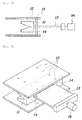
- FIG. 2 is a side view illustrating an edge mask according to an embodiment of the present invention
- FIG. 3 is a perspective view illustrating the edge mask according to an embodiment of the present invention.
- the cathode edge mask 11 according to an embodiment of the present invention is disposed to be adjacent to the edge portion of the steel plate in order to prevent the edge portion of the steel plate from being electrically connected to the anode.
- the cathode edge mask 11 has an inner recess in the direction toward the steel plate such that the edge portion can pass through the recess when the steel plate is subjected to continuous plating, whereby the anode is prevented from being electrically connected to the edge portion of the steel plate.
- the recess has an inclined cross-section that spreads in the direction toward the steel plate. This configuration can reliably reduce the current density at the edge portion of the steel plate when the distance between the steel plate and the cathode edge mask 11 varies in response to the steel plate slipping to the right or left in the width direction during continuous plating.
- a support 13 is connected to the other surface of the cathode edge mask 11.
- One end of the support 13 is connected to a mask driving unit 16 that moves the cathode edge mask 11 forward and backward.
- the mask driving unit 16 can move the cathode edge mask 11 toward or away from the steel plate, thereby adjusting the position of the cathode edge mask 11 with respect to the steel plate.
- the mask driving unit 16 may be a device able to execute forward and reverse motions, for example, a cylinder device.
- the mask driving unit 16 may be actuated using a servomotor for the purpose of precise control.
- the support 13 is coupled with connecting portions 14 that extend in the top-bottom direction such that the connecting portions 14 can be coupled with an anode edge mask.
- the connecting portions 14 may extend through the support 13, and may be in the shape of two rods positioned at both sides.
- the connecting portions 14 can be fitted into positioning holes 15 formed in the anode edge mask 12, thereby being coupled with the anode edge mask 12.
- a pair of the anode edge masks 12 may be coupled with the connecting portions 14 such that the anode edge masks 12 are disposed parallel to each other on both sides of the cathode edge mask 11. Since the two or more positioning holes 15 may be formed in the direction toward the steel plate, the area by which the anode is covered can be adjusted in response to the positions of the positioning holes 15 coupled with the connecting portions 14, thereby adjusting the current density at the steel plate.
- the cathode edge mask 11 and the anode edge masks 12 may be formed of an insulating material.
- the anode edge masks 12 may be formed of a conductive material in order to prevent the problem that the portions of the steel plate covered by the anode edge masks 12 are non-plated.
- the anode edge masks 12 may have an insulating layer on the surfaces facing anodes 2 and 3 in order to prevent the anode edge masks 12 from being electrically connected to the anodes 2 and 3. This configuration can prevent the problem that the surface portions of the steel plate covered by the anode edge masks 12 are non-plated.
- FIG. 4 is a schematic cross-sectional view illustrating an electroplating apparatus for preventing edge portions from being over-plated according to an embodiment of the present invention.
- the steel plate 1 is positively charged to act as a cathode, and electroplating proceeds while the steel plate 1 passes between the two anodes 2 and 3. At this time, the edge portions on both sides of the steel plate 1 may be over-plated in response to current density being concentrated thereon.
- the cathode edge masks 11 are disposed adjacent to the steel plate in order to reduce the current density. Even in the case where the distance between the cathode edge masks 11 and the edge portions of the steel plate is increased, the anodes are covered by the anode masks 12 disposed between the cathode edge masks 11 and the anodes 2 and 3, whereby the current density at the edge portions can be reduced.
- anode edge mask 12 extends more than the cathode edge masks 11 in the direction toward the steel plate 1. This configuration prevents the current density from significantly increasing at the edge portions even in the case where the distance between the edge portions of the steel plate 1 and the cathode edge masks 11 is rather increased in response to the steel plate slipping in the width direction while passing between the cathode edge masks.
Landscapes
- Chemical & Material Sciences (AREA)
- Engineering & Computer Science (AREA)
- Chemical Kinetics & Catalysis (AREA)
- Electrochemistry (AREA)
- Materials Engineering (AREA)
- Metallurgy (AREA)
- Organic Chemistry (AREA)
- Electroplating Methods And Accessories (AREA)
Applications Claiming Priority (2)
| Application Number | Priority Date | Filing Date | Title |
|---|---|---|---|
| KR20130038912A KR101495419B1 (ko) | 2013-04-10 | 2013-04-10 | 에지 과도금을 방지하기 위한 전기도금장치 |
| PCT/KR2013/011554 WO2014168314A1 (fr) | 2013-04-10 | 2013-12-12 | Appareil d'électroplaquage pour empêcher le plaquage excessif d'un bord |
Publications (2)
| Publication Number | Publication Date |
|---|---|
| EP2985367A1 true EP2985367A1 (fr) | 2016-02-17 |
| EP2985367A4 EP2985367A4 (fr) | 2016-12-28 |
Family
ID=51689696
Family Applications (1)
| Application Number | Title | Priority Date | Filing Date |
|---|---|---|---|
| EP13881849.7A Withdrawn EP2985367A4 (fr) | 2013-04-10 | 2013-12-12 | Appareil d'électroplaquage pour empêcher le plaquage excessif d'un bord |
Country Status (6)
| Country | Link |
|---|---|
| US (1) | US20160076166A1 (fr) |
| EP (1) | EP2985367A4 (fr) |
| JP (1) | JP6089125B2 (fr) |
| KR (1) | KR101495419B1 (fr) |
| CN (1) | CN105189830B (fr) |
| WO (1) | WO2014168314A1 (fr) |
Families Citing this family (10)
| Publication number | Priority date | Publication date | Assignee | Title |
|---|---|---|---|---|
| KR101633617B1 (ko) * | 2014-12-12 | 2016-06-28 | 주식회사 포스코 | 수평셀 전기도금장치의 에지마스크 및 이를 포함하는 수평셀 전기도금장치 |
| KR101666461B1 (ko) | 2014-12-24 | 2016-10-14 | 주식회사 포스코 | 에지 영역 과도금 방지를 위한 전기 도금 장치 |
| KR101674793B1 (ko) * | 2015-03-02 | 2016-11-10 | 주식회사 포스코 | 유체유동을 이용한 센터링장치 및 이를 포함하는 전기도금설비 |
| DE102016111649A1 (de) * | 2016-06-24 | 2017-12-28 | Thyssenkrupp Ag | Vorrichtung und Verfahren zur elektrolytischen Beschichtung eines Metallbandes |
| JP6839992B2 (ja) * | 2017-02-03 | 2021-03-10 | Dowaメタルテック株式会社 | めっき方法およびその装置 |
| KR102065220B1 (ko) | 2017-12-22 | 2020-01-10 | 주식회사 포스코 | 에지 마스크를 구비한 전기 도금 장치 |
| CN109234776B (zh) * | 2018-09-17 | 2020-04-10 | 芜湖海成科技有限公司 | 一种便捷式导电工装 |
| KR102022920B1 (ko) * | 2019-06-25 | 2019-09-19 | 주식회사 태성 | 롤투롤 수평식 연속 도금장치 |
| EP4389940A1 (fr) * | 2022-12-21 | 2024-06-26 | John Cockerill SA | Dispositif pour une electrodeposition anti-dendrites |
| KR102674486B1 (ko) * | 2024-03-14 | 2024-06-11 | 주식회사 티티엠기술연구소 | 수직형 가용성 전기 니켈 도금조용 과도금 방지를 위한 엣지 마스크 |
Family Cites Families (10)
| Publication number | Priority date | Publication date | Assignee | Title |
|---|---|---|---|---|
| JPH08239796A (ja) * | 1995-03-01 | 1996-09-17 | Nippon Steel Corp | 電気めっき用エッジマスク装置および電気めっき方法 |
| FR2750438B1 (fr) * | 1996-06-27 | 1998-08-07 | Usinor Sacilor | Procede et installation de revetement electrolytique par une couche metallique de la surface d'un cylindre pour coulee continue de bandes metalliques minces |
| DE19717510C1 (de) * | 1997-04-25 | 1998-10-01 | Atotech Deutschland Gmbh | Vorrichtung zur Abblendung von Galvanisiergut in Durchlaufanlagen |
| JP4177902B2 (ja) * | 1998-04-23 | 2008-11-05 | アトーテヒ ドイッチュラント ゲゼルシャフト ミット ベシュレンクテル ハフツング | プレート形状の被処理物を電気分解的に処理するための装置と電気分解的処理の際に被処理物のエッジ範囲を電気的に遮蔽するための方法 |
| KR20010059601A (ko) * | 1999-12-30 | 2001-07-06 | 이구택 | 에지부 도금층이 균일한 전기도금방법 |
| JP3508725B2 (ja) * | 2001-02-07 | 2004-03-22 | Jfeスチール株式会社 | 鋼帯の電気めっき装置および電気めっき鋼帯の製造方法 |
| JP3935858B2 (ja) * | 2003-04-18 | 2007-06-27 | 新日本製鐵株式会社 | 連続式電気めっき設備のエッジマスク装置 |
| US20060037865A1 (en) * | 2004-08-19 | 2006-02-23 | Rucker Michael H | Methods and apparatus for fabricating gas turbine engines |
| JP4977046B2 (ja) | 2008-01-21 | 2012-07-18 | Jx日鉱日石金属株式会社 | エッジオーバーコート防止装置及びそれを用いた電気めっき材の製造方法 |
| CN202509143U (zh) * | 2012-02-01 | 2012-10-31 | 湖南中精伦金属材料有限公司 | 一种电镀镍边缘屏蔽装置 |
-
2013
- 2013-04-10 KR KR20130038912A patent/KR101495419B1/ko active Active
- 2013-12-12 CN CN201380074786.5A patent/CN105189830B/zh active Active
- 2013-12-12 US US14/783,836 patent/US20160076166A1/en not_active Abandoned
- 2013-12-12 JP JP2015562897A patent/JP6089125B2/ja not_active Expired - Fee Related
- 2013-12-12 WO PCT/KR2013/011554 patent/WO2014168314A1/fr not_active Ceased
- 2013-12-12 EP EP13881849.7A patent/EP2985367A4/fr not_active Withdrawn
Also Published As
| Publication number | Publication date |
|---|---|
| CN105189830A (zh) | 2015-12-23 |
| JP6089125B2 (ja) | 2017-03-01 |
| WO2014168314A1 (fr) | 2014-10-16 |
| JP2016513752A (ja) | 2016-05-16 |
| KR20140122768A (ko) | 2014-10-21 |
| CN105189830B (zh) | 2018-03-06 |
| US20160076166A1 (en) | 2016-03-17 |
| EP2985367A4 (fr) | 2016-12-28 |
| KR101495419B1 (ko) | 2015-02-24 |
Similar Documents
| Publication | Publication Date | Title |
|---|---|---|
| EP2985367A1 (fr) | Appareil d'électroplaquage pour empêcher le plaquage excessif d'un bord | |
| CN101054701B (zh) | 提高电镀均匀性的方法 | |
| EP2641999A1 (fr) | Feuille de cuivre électrolytique | |
| JP4977046B2 (ja) | エッジオーバーコート防止装置及びそれを用いた電気めっき材の製造方法 | |
| KR101879080B1 (ko) | 철-니켈 합금 포일 제조장치 | |
| JP2013142169A (ja) | 電気めっき用保持具およびこの保持具を用いた電気めっき装置 | |
| JP2019183249A (ja) | アノード遮蔽板、電解めっき装置、および金属張積層板の製造方法 | |
| CN111118586A (zh) | 一种电镀夹具及电镀装置 | |
| KR101344065B1 (ko) | 구리 도금용액 | |
| US20050150776A1 (en) | Electrolytic etching method and apparatus | |
| CN214694432U (zh) | 一种阳极结构、电极机构及电镀系统 | |
| CN202954122U (zh) | 一种线路板电镀装置 | |
| KR102065220B1 (ko) | 에지 마스크를 구비한 전기 도금 장치 | |
| CN221371313U (zh) | 生箔设备 | |
| ES2779774B2 (es) | Proteccion lateral para catodo de cuba electolitica para produccion de zinc metalico | |
| US6966976B1 (en) | Electroplating panel with plating thickness-compensation structures | |
| KR101666461B1 (ko) | 에지 영역 과도금 방지를 위한 전기 도금 장치 | |
| CN210237831U (zh) | 垂直连续电镀中的下遮板结构 | |
| CN202808980U (zh) | 电镀辅助板及应用其的电镀设备 | |
| CN112779591A (zh) | 一种阳极结构、电极机构及电镀系统 | |
| CN104451785A (zh) | 一种卡槽式两极四触点电积、电解辅导电装置 | |
| JP2000290800A (ja) | 鋼帯の電解洗浄方法及び装置 | |
| KR101325337B1 (ko) | 수평 전주장치 | |
| JP3822136B2 (ja) | 銅箔の連続表面処理方法及び同装置 | |
| JP5977129B2 (ja) | 電解採取用アノード |
Legal Events
| Date | Code | Title | Description |
|---|---|---|---|
| PUAI | Public reference made under article 153(3) epc to a published international application that has entered the european phase |
Free format text: ORIGINAL CODE: 0009012 |
|
| 17P | Request for examination filed |
Effective date: 20151106 |
|
| AK | Designated contracting states |
Kind code of ref document: A1 Designated state(s): AL AT BE BG CH CY CZ DE DK EE ES FI FR GB GR HR HU IE IS IT LI LT LU LV MC MK MT NL NO PL PT RO RS SE SI SK SM TR |
|
| AX | Request for extension of the european patent |
Extension state: BA ME |
|
| DAX | Request for extension of the european patent (deleted) | ||
| A4 | Supplementary search report drawn up and despatched |
Effective date: 20161125 |
|
| RIC1 | Information provided on ipc code assigned before grant |
Ipc: C25D 17/00 20060101AFI20161118BHEP |
|
| 17Q | First examination report despatched |
Effective date: 20180605 |
|
| STAA | Information on the status of an ep patent application or granted ep patent |
Free format text: STATUS: THE APPLICATION IS DEEMED TO BE WITHDRAWN |
|
| 18D | Application deemed to be withdrawn |
Effective date: 20200825 |