EP2985505B1 - Système de congélateur de conduit - Google Patents
Système de congélateur de conduit Download PDFInfo
- Publication number
- EP2985505B1 EP2985505B1 EP15164146.1A EP15164146A EP2985505B1 EP 2985505 B1 EP2985505 B1 EP 2985505B1 EP 15164146 A EP15164146 A EP 15164146A EP 2985505 B1 EP2985505 B1 EP 2985505B1
- Authority
- EP
- European Patent Office
- Prior art keywords
- evaporator
- baffle
- refrigerant
- wall
- conduit
- Prior art date
- Legal status (The legal status is an assumption and is not a legal conclusion. Google has not performed a legal analysis and makes no representation as to the accuracy of the status listed.)
- Active
Links
Images





Classifications
-
- F—MECHANICAL ENGINEERING; LIGHTING; HEATING; WEAPONS; BLASTING
- F16—ENGINEERING ELEMENTS AND UNITS; GENERAL MEASURES FOR PRODUCING AND MAINTAINING EFFECTIVE FUNCTIONING OF MACHINES OR INSTALLATIONS; THERMAL INSULATION IN GENERAL
- F16L—PIPES; JOINTS OR FITTINGS FOR PIPES; SUPPORTS FOR PIPES, CABLES OR PROTECTIVE TUBING; MEANS FOR THERMAL INSULATION IN GENERAL
- F16L55/00—Devices or appurtenances for use in, or in connection with, pipes or pipe systems
- F16L55/10—Means for stopping flow in pipes or hoses
- F16L55/103—Means for stopping flow in pipes or hoses by temporarily freezing liquid sections in the pipe
Definitions
- This invention relates generally to a system for freezing the liquid contents of pipes to permit work on the pipe and, more particularly to a portable pipe freezer system that is designed to effectively freeze liquid in large diameter pipes.
- Pipe freezers are used in the repair or replacement of pipe sections or for repairing or adding fittings to existing pipe installations. Such systems are primarily used in fluid systems where it is not convenient or not readily possible to drain fluid in the pipe installation. By freezing the fluid in the pipe, it is possible to block the fluid in the section of pipe of interest by creating an ice plug.
- US Patent Nos. 5,548,965 and 6,598,412 which are assigned to the assignee of the current invention, use a refrigeration system with evaporator heads or adapters that are sized to fit various standard pipe diameters.
- the evaporator heads are connected by flexible coaxial tubes to a portable condenser/compressor unit that cycles refrigerant to and from the evaporation chambers.
- the refrigerant causes the evaporator heads to freeze the pipe where they are in contact.
- US-A 5,836,167 describes an apparatus for freezing large pipes, with a segmented rigid evaporator cuff that fits round the pipe.
- Liquid refrigerant from a compressor is injected at one corner of a segment of the cuff, and passes through a serpentine path with several parallel sections running lengthways of the cuff to the far side of the segment, where the refrigerant may be bridged over to a next segment.
- the evaporated refrigerant is eventually extracted from a point opposite where the liquid was injected, and returned to the compressor.
- WO-A 89/01110 describes an apparatus for freezing pipes, on which the preamble of claim 1 is based, with a two-part rigid evaporator cuff that fits round the pipe. Liquid refrigerant from a compressor is injected at one corner of one half the cuff, and passes through a serpentine path with several parallel sections running circumferentially of the cuff to the far side of the half cuff, where the refrigerant is bridged over to the other half cuff. The refrigerant then follows a symmetrical serpentine path through the second half cuff. The evaporated refrigerant is eventually extracted from a point on the second half cuff, adjacent to where the liquid was injected into the first half cuff, and returned to the compressor.
- WO-A 89/01110 also describes a flexible cuff for use with a heat transfer liquid that does not evaporate, in which the entering liquid is carried across one end of the serpentine, and then returns to an outlet near the inlet.
- EP-A 0 736 721 describes an apparatus for freezing escaping liquid at a rupture in a flat surface, with an evaporator in which liquid nitrogen is injected at the center of a flat device, and follows serpentine paths to two opposite corners, at which the evaporated nitrogen is allowed to escape.
- the device is sealed to the surface around the rupture by a flexible skirt, which contains the escaping liquid so that it can be more easily frozen in place.
- the present invention relates to an evaporator cuff as defined in claim 1 for use with a pipe freezer apparatus to freeze a large diameter pipe.
- the plurality of baffles include a first baffle formed between the inner wall and the outer wall and attached to the end wall.
- the first baffle defines a first conduit from the evaporator inlet in a direction away from the evaporator outlet so as to inhibit refrigerant entering the first conduit from passing directly into the evaporator outlet.
- the first baffle extends toward the first side wall and defines a first opening for providing a passage for refrigerant to flow out of the first conduit.
- a second baffle is located inward from the first side wall and extends from the first baffle the second end wall.
- the second baffle defines a second conduit that extends along the front of the evaporator to the opposite side of the evaporator chamber from the evaporator inlet.
- the second baffle has a second opening to allow refrigerant to flow out of the second conduit.
- a third baffle is located inward from the second end wall and extends away from the second baffle and toward the second side wall so as to define a third conduit.
- the third baffle has a third opening to allow refrigerant to flow out of the third conduit.
- a fourth baffle is formed in the chamber and spaced apart from the third baffle so as to define a fourth conduit.
- the fourth baffle extends from the second side wall toward the second baffle.
- the fourth baffle includes a fourth opening to allow refrigerant to flow out of the fourth conduit.
- a fifth baffle may be formed in the chamber and spaced apart from the fourth baffle so as to define a fifth conduit.
- the fifth baffle extends from the second baffle toward the second side wall.
- the fifth baffle includes a fifth opening that allows refrigerant to flow out of the fifth conduit.
- the fifth baffle may also include a sixth opening at or near the second baffle for providing a passage for refrigerant to flow out of the fifth conduit and toward the evaporator outlet.
- the fifth baffle may be spaced apart from the first baffle so as to define a sixth conduit for the refrigerant to flow from the sixth opening toward the evaporator outlet.
- a pipe freezer apparatus is also provided that incorporates the cuff described above.
- Another aspect of the invention provides a flow distributor designed to be connected to a condenser/compressor unit for receiving a single flow of refrigerant, the flow distributor including a divider for separating the single flow of refrigerant into multiple flow portions, and directing at least one of the refrigerant flow portions to each of at least two conduits.
- the flow distributor may include an intake section that is attached to an output from the condenser/compressor unit and includes an interior chamber, and a divider section that is mounted to the intake section and that includes a protruding surface located within the chamber of the intake section. At least two channels extend through the divider section from the protruding surface to an outlet side. The protruding surface is configured to divide the refrigerant flow and, in combination with an inner wall of the intake section, direct the refrigerant flow to the channels.
- the protruding surface may be conical in shape.
- a pipe freezer apparatus which may be in accordance with any of the other mentioned aspects of the invention, wherein there are at least two evaporator cuffs, each evaporator cuff having an associated fluid conduit that is configured to channel cooled refrigerant to that evaporator cuff, the apparatus further comprising the mentioned flow distributor connected to the two conduits that are configured to channel cooled refrigerant to the at least two evaporator cuffs, the flow distributor connected to the condenser/compressor unit for receiving a single flow of refrigerant, the flow distributor including the divider for separating the single flow of refrigerant into multiple flow portions, and directing at least one of the refrigerant flow portions to each conduit.
- the at least two evaporator cuffs may be two or four evaporator cuffs.
- the evaporator cuffs may be semi-cylindrical, and may be used in a pair or pairs to encircle the pipe at one or two locations.
- a pipe freezer system 10 for use in freezing large diameter pipes.
- the system 10 is shown installed on a pipe P to freeze the water W inside a section of pipe so as to form an ice plug.
- the system includes a condenser/compressor unit 12 that includes, in an embodiment, a compressor 14, a condenser 16, and one or more fans 18.
- the condenser/compressor unit 12 may also include a filter drier (not shown) positioned downstream from the condenser 16.
- the condenser/compressor unit 12 is preferably a portable unit.
- the system 10 includes one or more evaporator cuffs 20, each connected to the condenser/compressor unit by one or more hoses 22.
- the hose 22 is a flexible coaxial hose.
- the cuffs could be hinged together or separately mounted around the pipe.
- the coaxial hose includes an inner tube 24 and an outer tube 26.
- the inner tube 24 is a capillary tube that is configured to reduce the pressure of the refrigerant flowing through it. The entrance of the tube receives a flow of high pressure refrigerant from the condenser/compressor unit 12.
- the inner tube 22 delivers the flow of liquid refrigerant at low pressure and low temperature to the evaporator cuffs 20.
- the outer tube 26 returns refrigerant vapor from the evaporator cuffs 20 to the condenser/compressor unit 12.
- the compressor used in an embodiment is a horizontal rotary vane design that produces a desirable low temperature.
- any suitable compressor could be used in the system. It should be readily apparent that, instead of a coaxial hose 22, separate tubes 24, 26 could be used.
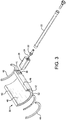
- the evaporator cuff 20 includes a hose connector 28 and an evaporator body 30.
- the hose connector 28 is attached to and protrudes out from one side of the evaporator body 30.
- the connector 28 is preferably fixedly attached to the body, such as by welding, but could also be removably attached to the body through other conventional means, such as threads.
- the coaxial hose 22 is attached to the connector 28, preferably through a removable connection, such as threads, a bayonet connection, or other connection capable of handling the pressures and temperatures inherent in the system.
- the hose 22 includes a threaded end 32 that mates with threads on an opening on one side of the connector 28. The threading of the end 32 to the connector 28 provides a fluid path from the outer tube 26 to the return channel 34 in the connector 28 that extends from where the end 32 of the hose attaches to the connector 28, through the connector 28 to an exit port 36.
- the inner tube 24 preferably does not attach to the connector 28. Instead, the inner tube preferably passes through a cavity 38 in the connector 28 and out through an entry port 37 formed in the connector 28. It is also contemplated that the inner tube 24 could connect to or terminate within the cavity if desired.
- the evaporator body 30 has an inner wall 40, an outer wall 42, first and second side walls 44, 46, and first and second end walls 48, 50.
- the inner wall 40 preferably has a shape that defines a portion of a cylinder, such as semi-cylindrical, so as to permit the inner wall 40 to conform to or substantially mate with the outer wall of a pipe that the evaporator is to be used on.
- the radius of the inner wall 40 is at least two inches (5.1 cm) so as to be useful for pipes having a diameter of at least four inches (10.2 cm). Of course, it should be readily apparent that the radius of the inner wall 40 can be larger if the intended pipe to be frozen has a larger diameter.
- the shape of the outer surface of the outer wall 42 is not critical since it is not configured to come into direct contact with the pipe. However, having an outer wall 42 that has a similar curvature to the inner wall 40 allows for more efficient circulation and cooling conduction.
- a cavity or fluid chamber 52 is located between the inner wall 40, outer wall 42, first and second side walls 44, 46 and first and second end walls, 48, 50.
- the inner tube 24 and the outer tube 26 are in fluid communication with the chamber 52. More particularly, the inner tube 26 preferably extends through the cavity 38 in the connector 28, out through the entry port 37 in the connector 28 and through an evaporator inlet 39 in the evaporator body 30 and into the chamber 52. Thus, liquid refrigerant passing through inner tube 24 can pass into the chamber 52.
- the exit port 36 on connector 28 is also in fluid communication with the chamber 52, and, in particular, with evaporator outlet 41.
- fluid from the chamber 52 can flow out of the evaporator outlet and into the exit port 36, through the return channel 34 in the connector 28 and back into the outer tube 26.
- the chamber 52 is preferably designed to facilitate refrigerant flow through the chamber so as to minimize any tendency oil that may be contained in the refrigerant to become significantly trapped in the chamber.
- the extension of the inner tube 24 into the chamber 52 allows liquid refrigerant under LOW pressure to enter the chamber 52 through the inner tube 24 of the evaporator.
- the inner tube acts as a metering device to spray the low pressure liquid refrigerant into the chamber 52, which is at low pressure. This causes the refrigerant to evaporate. As it does, it absorbs heat from the chamber 52 which, in turn, causes the evaporator to conduct heat from the pipe that it is connected to (and the water inside the pipe).
- the refrigerant vapor in the chamber 52 is drawn back from the evaporator through the outer tube 26 by suction.
- the suction draws the vapor through the outlet 41 and port 36, the return chamber 34 and into the outer tube 26.
- the refrigerant vapor flows into the compressor 14, which raises the pressure of the vapor.
- the high pressure vapor passes through the condenser 16, in which the vapor is exposed to a large cooling surface area that allows heat in the vapor to be removed.
- the condenser cools the refrigerant to its condensation temperature, which releases its heat, changing it back to its liquid phase at high pressure to complete the cycle.
- the heat is removed from the condenser by the fan 18.
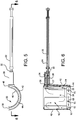
- the evaporator 30 includes a series of baffles to create a flow path through the chamber 52 for the refrigerant vapor to follow.
- a first baffle 54 is formed between the inner wall 40 and the outer wall 42 and attaches to the end wall 48.
- the first baffle 54 creates a first conduit 56 from the evaporator inlet 39 in a direction away from the evaporator outlet 41 so that refrigerant entering the first conduit 56 cannot pass directly out of the evaporator outlet 41.
- the first baffle 54 extends towards, but preferably stops short of, the first side wall 44 so as to define a first opening 55.
- a second baffle 58 is formed inward from the side wall 44 and extends from the first baffle 54 toward but preferably just short of the second end wall 50. This forms a second conduit 60 that extends along the front side of the evaporator so as to define a channel for the refrigerant to flow to the opposite side of the evaporator chamber 52 from where it entered. Intermediate walls with notches 61 may be incorporated to control flow of the refrigerant.
- a second opening 62 is formed between the end of the second baffle 58 and the second end wall 50 thereby providing a passage for the refrigerant gas to flow through.
- the second baffle 58 could extend to the second end wall and the second opening 62 can be a notch or cutout formed in the second baffle 58 near the second end wall 50.
- a third baffle 64 is formed in the chamber 52 and extends preferably parallel to and spaced apart from the second end wall 50 so as to define a third conduit 66 for the refrigerant to flow along.
- the third baffle 64 extends from the second baffle 58 toward the second side wall 46.
- the third baffle either stops short of the second side wall 46 or is notched or otherwise cut so as to form a third opening 68 for the refrigerant to flow through.
- a fourth baffle 70 is formed in the chamber 52 and extends preferably parallel to and spaced apart from the third baffle 64 so as to define a fourth conduit 72 for the refrigerant to flow along.
- the fourth baffle 70 extends from the second side wall 46 toward the second baffle 58.
- the fourth baffle 70 either stops short of the second baffle 58 or is notched or otherwise cut so as to form a fourth opening 74 for the refrigerant to flow through.
- a fifth baffle 76 is formed in the chamber 52 and extends preferably parallel to and spaced apart from the fourth baffle 70 so as to define a fifth conduit 78 for the refrigerant to flow along.
- the fifth baffle 76 preferably extends from the second baffle 58 toward the second side wall 46.
- the fifth baffle 76 either stops short of the second side wall 46 or is notched or otherwise cut so as to form a fifth opening 80 for the refrigerant to flow through.
- a sixth opening 82 is formed in the fifth baffle at or near the second baffle 58 so as to define a further opening for the refrigerant to flow through.
- the fifth baffle 76 is also spaced apart from the first baffle 54 so as to define a sixth conduit 84 for the refrigerant to flow along.
- the evaporator outlet 41 is formed in the outer wall 42 and is aligned with the exit port 36 on the connector.
- the evaporator outlet 41 communicates with the sixth conduit so as to provide an opening through which the refrigerant can flow out of the chamber 52 and into the return channel 34 in the connector 28.
- the baffles in the evaporator 52 define a continuous serpentine path for the refrigerant to flow along.
- the serpentine path provides an efficient system for heat transfer so as to cover the entire evaporator. While the illustrated embodiment uses six baffles, more or less baffles can be used so long as the refrigerant flows continuously through the evaporator.
- the inner wall 40 preferably has a shape that defines a portion of a cylinder, such as semi-cylindrical.
- a second evaporator cuff would be placed on the opposite side of the pipe so as to cover the majority of the circumference.
- the two evaporator cuffs can be removably attached to the pipe, such as by a strap or bolts.
- the inventor has determined that the current configuration of the pipe freezing apparatus is capable for producing a refrigerant temperature of -70 degrees F (-55 °C) or lower using conventional refrigerant, such as R-507 (sold by Honeywell) or R-404A (sold by DuPont), which is considerably below the required temperature of -55 degrees F (-50 °C) for producing an ice plug in a large diameter pipe, e.g., having a diameter of four inches (10.2 cm) or more.
- conventional refrigerant such as R-507 (sold by Honeywell) or R-404A (sold by DuPont
- the present embodiment contemplates that there would be two evaporator cuffs used to create an ice plug inside a diameter of pipe.
- a temperature differential could develop between the two evaporator cuffs 20 due to supply of uneven amounts of refrigerant. This can be problematic since it could lead to inconsistent freezing and, thus, might not yield a complete ice plug in the pipe.
- evaporator temperature of approximately -80° F (-60 °C). This is an extremely low temperature and difficult to obtain.
- Embodiments of the present invention are designed to reach that temperature through the innovative system described above.
- temperature losses as the refrigerant is channeled to the evaporator cuffs can result in a variation from this temperature.
- Temperatur differentials can be as much as 10° F (5 °C) (i.e., one evaporator cuff at -80° F (-60 °C) and the other at -70° F (-55 °C)) or more.
- the present invention includes copper intake capillary tubes 24 which provide for minimal permeation. Even with that change, there can be unevenness in evaporator cuff temperatures.
- the present apparatus includes a flow distributor 100 for controlling refrigerant flow to the evaporator cuffs by separation of the refrigerant flow into the two (or more) capillary tubes 24.
- the flow distributor 100 is preferably located downstream from the condenser 12 (or if there is a filter drier, downstream from that) at the intake to the capillary tubes 24.
- the flow divider 102 is shown in Figs. 10 and 10A and includes a housing 114 with a dividing end 116 and an output end 118. At least two channels 120 extend from the dividing end 116 to the output end 118.
- the channels 120 are preferably substantially identical in diameter to one another and symmetrically located in the housing 114.
- the channels 120 are also preferably similar in diameter to the capillary tubes 24.
- the channels 120 provide conduits for directing refrigerant from the dividing end through the housing 114 and out the output end 118.
- the dividing end includes a protruding surface configured to separate the refrigerant flow into two (or more) fluid streams.
- the dividing end has a conical or cone-shaped surface that forms an angle A of between about 20 degrees and about 60 degrees. In one embodiment, angle A is about 55 degrees. However it should be readily apparent that other angles can be used.
- the surface need not be a conical surface, but could be any curved shape that will channel the refrigerant flow, including parabolic, complex, etc. It is also contemplated that the dividing end may, instead, be wedge-shaped with opposed sloped surfaces.
- the channels 120 have an open end that is positioned along the curved or sloped surfaces of the dividing end 116. The shape of the dividing end is designed to help reduce turbulence at the entrance of the channels 120.
- the channels 120 are configured to receive or attach to the capillary tubes 24 so as to provide a smooth flow of the refrigerant from the channels 120 into tubes 24.
- the divider section 102 preferably includes a flange 122 formed on the housing adjacent to the curved or sloped surface 116 which is configured to seat on the land 112 in the intake section 104 as shown in Fig. 9A so as to position the dividing end 116 within the interior of the housing 106.
- the tip of the dividing end 116 and the inner wall 124 of the intake housing 106 will cause the refrigerant to separate into distinct flow portions that are then directed by the intake housing 106 and the dividing end 116 into the channels 120, thus minimizing turbulence.
- a sloped surface 126 can be machined into the inner wall 124 near the tip of the dividing end 116 in order to further facilitate the separation of the flow.
- the sloped surface has a conical shape with an angle of about 45 degrees. However other shapes and angles can be used.
- the flow distributor 100 provides a unique mechanism for accurately separating the refrigerant flow into distinct flow portions and to reduce turbulence, thereby minimizing temperature differentials between refrigerant flows entering the evaporator cuffs. Testing has determined that the use of the flow distributor 100 reduced temperature differentials to less than 2° F (1 °C).
Landscapes
- Engineering & Computer Science (AREA)
- General Engineering & Computer Science (AREA)
- Mechanical Engineering (AREA)
- Devices That Are Associated With Refrigeration Equipment (AREA)
- Pipe Accessories (AREA)
- Heat-Exchange Devices With Radiators And Conduit Assemblies (AREA)
- Chemical & Material Sciences (AREA)
- Combustion & Propulsion (AREA)
- Physics & Mathematics (AREA)
- Thermal Sciences (AREA)
Claims (15)
- Un manchon d'évaporateur destiné à être utilisé avec un appareil de congélation de conduite, le manchon d'évaporateur comprenant :un raccord de tuyau (28) avec une première cavité (38) et un canal de retour (34) ;un corps d'évaporateur (30) attaché au raccord de tuyau, le corps d'évaporateur incluant une paroi interne (40) ayant un contour qui délimite une portion d'un cylindre et configuré pour se mettre en prise avec la surface externe d'une conduite (C), une paroi externe (42) espacée de la paroi interne, des première et deuxième parois latérales (44, 46) raccordant la paroi externe (42) à la paroi interne (40), et des première et deuxième parois d'extrémité (48, 50) raccordant la paroi externe (42) à la paroi interne (40), une chambre (52) délimitée entre la paroi interne (40), la paroi externe (42), les première et deuxième parois latérales (44, 46), et les première et deuxième parois d'extrémité (48, 50), une entrée d'évaporateur (37) formée dans le corps d'évaporateur (30) et en communication fluidique avec la première cavité (38) du raccord de tuyau (28), et une sortie d'évaporateur (36) formée dans le corps d'évaporateur (30) en communication fluidique avec le canal de retour (34) du raccord de tuyau (28) ; etune pluralité de déflecteurs comprenant au moins des premier, deuxième, troisième, et quatrième déflecteurs (54, 58, 64, 70) situés dans la chambre et agencés pour délimiter une série d'au moins premier, deuxième, troisième, quatrième, et cinquième conduits (56, 60, 66, 72, 78) afin de créer un trajet d'écoulement à travers la chambre (52) pour que du réfrigérant s'y écoule, les déflecteurs (54, 58, 64, 70) étant agencés de manière à former un trajet d'écoulement serpentin depuis l'entrée d'évaporateur jusqu'à la sortie d'évaporateur ;où les troisième et quatrième déflecteurs (64, 70) délimitent au moins en partie un trajet d'écoulement pour du fluide en contact avec la paroi interne (40), le trajet d'écoulement serpentin ayant le troisième conduit (66) dans lequel le fluide s'écoule dans une première direction à l'extérieur du troisième déflecteur (64), le quatrième conduit (72) dans lequel le fluide s'écoule dans une direction opposée entre les troisième etquatrième déflecteurs (64, 70), et le cinquième conduit (78) dans lequel le fluide s'écoule dans la première direction (78, 84) à l'extérieur du quatrième déflecteur (70) ; le premier déflecteur (54) délimitant en partie le premier conduit de fluide (56) de la série de conduits depuis l'entrée d'évaporateur (37) jusque dans le trajet d'écoulement serpentin (66, 72, 78, 84) ou depuis une extrémité du trajet d'écoulement serpentin jusqu'à la sortie d'évaporateur (36) ;où le premier déflecteur (54) enferme l'entrée d'évaporateur (37) et le premier déflecteur (54) s'étend vers la première paroi latérale (44) délimite au moins en partie une première ouverture (55) au niveau d'une extrémité du premier déflecteur (54) distante de l'entrée d'évaporateur (37) pour fournir un passage pour que du réfrigérant s'écoule hors du premier conduit (56) ;le premier déflecteur (54) crée le premier conduit (56) de la série de conduits depuis l'entrée d'évaporateur (37) dans une direction qui s'éloigne de la sortie d'évaporateur (36) de manière à empêcher du réfrigérant entrant dans le premier conduit (56) de passer directement dans la sortie d'évaporateur (36) ; etcaractérisé en ce quel'entrée d'évaporateur est enfermée par une extrémité du premier déflecteur ; etle deuxième déflecteur (58) est espacé vers l'intérieur depuis la première paroi latérale (44) et s'étend le long de la première paroi latérale (44) depuis le premier déflecteur (54) vers la deuxième paroi d'extrémité (50), le deuxième déflecteur (58) délimitant un deuxième conduit (60) qui s'étend le long de la première paroi latérale (44) de l'évaporateur depuis l'entrée d'évaporateur jusqu'à la deuxième paroi d'extrémité (50) de la chambre d'évaporateur (52), le deuxième déflecteur (58) délimitant au moins en partie une deuxième ouverture (62) au niveau d'une portion d'extrémité du deuxième déflecteur adjacente à la deuxième paroi d'extrémité (50) pour fournir un passage pour que du réfrigérant s'écoule hors du deuxième conduit.
- Le manchon d'évaporateur de la revendication 1, où la sortie d'évaporateur (36) est formée adjacente à un coin formé par la première paroi d'extrémité (48) et la deuxième paroi latérale (46), et l'entrée d'évaporateur (37) est adjacente à la sortie d'évaporateur (36).
- Le manchon d'évaporateur de la revendication 1 ou de la revendication 2, où :le troisième déflecteur (64) est espacé vers l'intérieur depuis la deuxième paroi d'extrémité (50) et s'étend depuis le deuxième déflecteur (58) et vers la deuxième paroi latérale (46) de manière à délimiter le troisième conduit (66), le troisième déflecteur (64) délimitant au moins en partie une troisième ouverture (68) au niveau d'une portion d'extrémité du troisième déflecteur adjacente à la deuxième paroi latérale (46) fournissant un passage pour que du réfrigérant s'écoule hors du troisième conduit (66) ; etle quatrième déflecteur (70) s'étend depuis la deuxième paroi latérale (46) vers le deuxième déflecteur (58), le quatrième déflecteur (70) délimite au moins en partie une quatrième ouverture (74) au niveau d'une portion d'extrémité du quatrième déflecteur la plus proche du deuxième déflecteur (58) fournissant un passage pour que du réfrigérant s'écoule hors du quatrième conduit (72).
- Le manchon d'évaporateur de la revendication 3, où la pluralité de déflecteurs comprend un cinquième déflecteur (76) situé dans la chambre (52) et espacé du quatrième déflecteur (70) de manière à délimiter le cinquième conduit (78), le cinquième déflecteur (76) s'étendant depuis le deuxième déflecteur (58) vers la deuxième paroi latérale (46), le cinquième déflecteur (76) délimitant une cinquième ouverture (80) pour fournir un passage pour que du réfrigérant s'écoule hors du cinquième conduit (78).
- Le manchon d'évaporateur de la revendication 4, où le cinquième déflecteur (76) délimite au moins en partie la cinquième ouverture (80) au niveau d'une portion d'extrémité du cinquième déflecteur (76) adjacente à la deuxième paroi latérale (46) et une sixième ouverture (82) au niveau d'une portion d'extrémité du cinquième déflecteur (76) adjacente au deuxième déflecteur pour fournir un passage pour que du réfrigérant s'écoule hors du cinquième conduit (78) et vers la sortie d'évaporateur (36) ; et où le cinquième déflecteur (76) est facultativement espacé du premier déflecteur (54) de manière à délimiter un sixième conduit (84) pour que du réfrigérant s'écoule depuis la sixième ouverture (82) vers la sortie d'évaporateur (36).
- Le manchon d'évaporateur de n'importe lesquelles des revendications 1 à 5, où les première et deuxième parois d'extrémité (48, 50) sont au niveau d'extrémités circonférentielles de la paroi interne (40) par rapport au cylindre dont une portion est délimitée par la paroi interne (40), et les première et deuxième parois latérales (44, 46) sont au niveau de côtés axiaux de la paroi interne (40) par rapport au cylindre.
- Le manchon d'évaporateur de n'importe lesquelles des revendications 1 à 6, comprenant en outre des parois intermédiaires pour contrôler l'écoulement de réfrigérant dans le deuxième conduit (60).
- Le manchon d'évaporateur de la revendication 7, où les parois intermédiaires ont des encoches (61) pour contrôler l'écoulement de réfrigérant.
- Le manchon d'évaporateur de n'importe lesquelles des revendications 1 à 8, où le raccord de tuyau (28) s'attache à un tuyau coaxial et fournit un trajet de fluide depuis un tube externe (26) du tuyau coaxial (22) jusqu'au canal de retour (34) dans le raccord (28).
- Le manchon d'évaporateur de la revendication 9, où un tube interne (24) du tuyau coaxial (22) passe à travers la première cavité (38) dans le raccord (28) et sort par l'entrée d'évaporateur (37).
- Un appareil de congélation de conduite (10) comprenant :au moins un manchon d'évaporateur (20) selon n'importe lesquelles des revendications 1 à 8 ;une unité formant condenseur/compresseur (12) ; etau moins deux conduits de fluide (24, 26) pouvant être raccordés au manchon d'évaporateur (20) et à l'unité formant condenseur/compresseur (12), l'un des conduits de fluide (24) étant configuré pour canaliser du réfrigérant refroidi jusqu'au manchon d'évaporateur (20) depuis l'unité formant condenseur/compresseur (12) et un autre des conduits de fluide (26) étant configuré pour canaliser du réfrigérant réchauffé jusqu'à l'unité formant condenseur/compresseur (12).
- L'appareil de congélation de conduite de la revendication 11, où les conduits de fluide (24, 26) sont disposés de façon coaxiale.
- L'appareil de congélation de conduite de la revendication 11 ou de la revendication 12, où il y a au moins deux manchons d'évaporateur (20), chaque manchon d'évaporateur (20) ayant un conduit de fluide associé (24) qui est configuré pour canaliser du réfrigérant refroidi jusqu'à ce manchon d'évaporateur (20), l'appareil comprenant en outre un distributeur d'écoulement (100) raccordé aux deux conduits (24) qui sont configurés pour canaliser du réfrigérant refroidi jusqu'aux deux manchons d'évaporateur (20), le distributeur d'écoulement (100) étant raccordé à l'unité formant condenseur/compresseur (12) pour recevoir un écoulement unique de réfrigérant, le distributeur d'écoulement incluant un diviseur (102, 116) pour séparer l'écoulement unique de réfrigérant en portions d'écoulement multiples, et diriger au moins une des portions d'écoulement de réfrigérant jusqu'à chaque conduit (24).
- L'appareil de congélation de conduite de la revendication 13, où le distributeur d'écoulement (100) inclut une section d'admission (104) qui est attachée à une sortie de l'unité formant condenseur/compresseur (12) et inclut une chambre intérieure, et une section de division (102) qui est montée sur la section d'admission (104) et qui inclut une surface en saillie (116) située au sein de la chambre de la section d'admission (104), au moins deux canaux (120) s'étendant à travers la section de division depuis la surface en saillie (116) jusqu'à un côté de sortie (118), la surface en saillie (116) étant configurée pour diviser l'écoulement de réfrigérant et, en combinaison avec une paroi interne (124) de la section d'admission, diriger l'écoulement de réfrigérant jusqu'aux canaux (120).
- L'appareil de congélation de conduite de la revendication 14, où la surface en saillie (116) est de forme conique.
Applications Claiming Priority (1)
| Application Number | Priority Date | Filing Date | Title |
|---|---|---|---|
| US14/456,502 US9574694B2 (en) | 2014-08-11 | 2014-08-11 | Pipe freezer system |
Publications (2)
| Publication Number | Publication Date |
|---|---|
| EP2985505A1 EP2985505A1 (fr) | 2016-02-17 |
| EP2985505B1 true EP2985505B1 (fr) | 2017-09-13 |
Family
ID=52946446
Family Applications (1)
| Application Number | Title | Priority Date | Filing Date |
|---|---|---|---|
| EP15164146.1A Active EP2985505B1 (fr) | 2014-08-11 | 2015-04-17 | Système de congélateur de conduit |
Country Status (4)
| Country | Link |
|---|---|
| US (1) | US9574694B2 (fr) |
| EP (1) | EP2985505B1 (fr) |
| JP (1) | JP6215275B2 (fr) |
| CN (1) | CN105371534B (fr) |
Families Citing this family (4)
| Publication number | Priority date | Publication date | Assignee | Title |
|---|---|---|---|---|
| GB2547709A (en) * | 2016-02-29 | 2017-08-30 | Pttg Ltd | Freezing of pipes |
| WO2019208124A1 (fr) * | 2018-04-25 | 2019-10-31 | パナソニック株式会社 | Dispositif de récupération de chaleur, dispositif à cycle de rankine et procédé de récupération de chaleur |
| CN111551378A (zh) * | 2020-04-26 | 2020-08-18 | 中国电子产品可靠性与环境试验研究所((工业和信息化部电子第五研究所)(中国赛宝实验室)) | 适用于液氮冷却设备的可靠性试验装置以及试验系统 |
| CN112762633A (zh) * | 2021-02-26 | 2021-05-07 | 万智豹 | 一种高性能防过温设备 |
Citations (1)
| Publication number | Priority date | Publication date | Assignee | Title |
|---|---|---|---|---|
| US2566865A (en) * | 1946-12-26 | 1951-09-04 | Wingerter Ralph | Portable refrigerator |
Family Cites Families (15)
| Publication number | Priority date | Publication date | Assignee | Title |
|---|---|---|---|---|
| US4267699A (en) * | 1979-02-21 | 1981-05-19 | Bahrenburg Harry H | Freeze isolation seal |
| JPS5811364A (ja) * | 1981-07-10 | 1983-01-22 | 株式会社前川製作所 | 冷媒循環装置 |
| US4492095A (en) * | 1981-12-08 | 1985-01-08 | Brister, Incorporated | Apparatus and method for forming a temporary plug in a fluid conduit |
| WO1989001110A1 (fr) | 1987-07-30 | 1989-02-09 | Pakkastappi Oy | Dispositif de transfert thermique |
| DE8802515U1 (de) * | 1988-02-26 | 1988-05-26 | Sanden, Josephus Antonius, van der, Eindhoven | Vorrichtung zum Einfrieren von Flüssigkeit führenden Rohren |
| EP0736721A1 (fr) | 1995-04-08 | 1996-10-09 | Winkler, Konrad, Dr.-Ing. habil. | Appareil pour colmater une fuite d'un réservoir |
| DE19516454A1 (de) | 1995-05-04 | 1996-11-07 | Alexander Dr Flos | Sanitärrohr-Vereisungsvorrichtung |
| US5548965A (en) * | 1995-05-31 | 1996-08-27 | Spectronics Corporation | Multi-cavity evaporator |
| US5836167A (en) | 1995-09-18 | 1998-11-17 | Nowsco Well Service Ltd. | Method and apparatus for freezing large pipe |
| WO1997011326A1 (fr) * | 1995-09-18 | 1997-03-27 | Nowsco Well Service, Inc. | Procede et dispositif pour refrigerer de gros tuyaux |
| DE19710566C2 (de) | 1996-06-19 | 1998-10-22 | Rothenberger Werkzeuge Ag | Einfriervorrichtung für flüssigkeitsgefüllte Rohrleitungen |
| US6598412B1 (en) | 2002-05-21 | 2003-07-29 | Spectronics Corporation | Interchangeable adapters for pipe freezer apparatus |
| JP5320884B2 (ja) * | 2008-07-23 | 2013-10-23 | ダイキン工業株式会社 | 食い込み式管接続構造、弁、食い込み式管継手及び冷凍装置 |
| CN202885364U (zh) * | 2012-09-27 | 2013-04-17 | 广东美的制冷设备有限公司 | 冷媒分流装置及平行流换热器 |
| CN202993693U (zh) * | 2012-11-30 | 2013-06-12 | 广东美的电器股份有限公司 | 空调器及其冷媒分配器 |
-
2014
- 2014-08-11 US US14/456,502 patent/US9574694B2/en active Active
-
2015
- 2015-04-17 EP EP15164146.1A patent/EP2985505B1/fr active Active
- 2015-08-10 JP JP2015158412A patent/JP6215275B2/ja active Active
- 2015-08-11 CN CN201510490658.XA patent/CN105371534B/zh active Active
Patent Citations (1)
| Publication number | Priority date | Publication date | Assignee | Title |
|---|---|---|---|---|
| US2566865A (en) * | 1946-12-26 | 1951-09-04 | Wingerter Ralph | Portable refrigerator |
Also Published As
| Publication number | Publication date |
|---|---|
| JP2016038199A (ja) | 2016-03-22 |
| CN105371534A (zh) | 2016-03-02 |
| US9574694B2 (en) | 2017-02-21 |
| JP6215275B2 (ja) | 2017-10-18 |
| US20160040818A1 (en) | 2016-02-11 |
| EP2985505A1 (fr) | 2016-02-17 |
| CN105371534B (zh) | 2018-07-03 |
Similar Documents
| Publication | Publication Date | Title |
|---|---|---|
| EP2985505B1 (fr) | Système de congélateur de conduit | |
| US4193443A (en) | Heat exchanger for cooling system compressed air dehumidifiers | |
| US4309875A (en) | Pipe freezer or the like | |
| JPH0933165A (ja) | マルチキャビティ蒸発器 | |
| US20140182317A1 (en) | Economized Centrifugal Compressor | |
| EP0145114B1 (fr) | Dispositif pour congélation d'un conduit | |
| JPS60117061A (ja) | 液体冷凍剤の気化流出の凝縮装置 | |
| RU2147102C1 (ru) | Поверхностный теплообменник | |
| US20100236283A1 (en) | Refrigerant Accumulator | |
| WO2014140939A2 (fr) | Traceur pour pipeline | |
| CN102095290B (zh) | 冰晶蒸发器及用其制作的冰晶水制冷装置 | |
| JP6339606B2 (ja) | 多重管式冷却器およびこれを用いた冷水機 | |
| CN104757879A (zh) | 供水设备 | |
| US6598412B1 (en) | Interchangeable adapters for pipe freezer apparatus | |
| CN109990515A (zh) | 一种带经济器功能的热交换气液分离器 | |
| US8424593B2 (en) | Pressurized-gas cooler for a compressor | |
| JP7133293B2 (ja) | 多重管式冷却器およびこれを用いた冷水機 | |
| US20180259227A1 (en) | Vortex tube | |
| US9823002B1 (en) | System to cool beverages using a refrigeration system having a defrosting feature | |
| US6408638B1 (en) | Pipe freezer with quick connect evaporator heads | |
| JPH0217297A (ja) | 導管を凍結によつて閉塞する方法及びこの方法を実施するための装置 | |
| CN210638342U (zh) | 分离器及平衡系统 | |
| US4281710A (en) | Heat exchanger | |
| CN112212550B (zh) | 分离器及平衡系统 | |
| RU2104449C1 (ru) | Блок сжижения газа |
Legal Events
| Date | Code | Title | Description |
|---|---|---|---|
| PUAI | Public reference made under article 153(3) epc to a published international application that has entered the european phase |
Free format text: ORIGINAL CODE: 0009012 |
|
| AK | Designated contracting states |
Kind code of ref document: A1 Designated state(s): AL AT BE BG CH CY CZ DE DK EE ES FI FR GB GR HR HU IE IS IT LI LT LU LV MC MK MT NL NO PL PT RO RS SE SI SK SM TR |
|
| AX | Request for extension of the european patent |
Extension state: BA ME |
|
| 17P | Request for examination filed |
Effective date: 20160803 |
|
| RBV | Designated contracting states (corrected) |
Designated state(s): AL AT BE BG CH CY CZ DE DK EE ES FI FR GB GR HR HU IE IS IT LI LT LU LV MC MK MT NL NO PL PT RO RS SE SI SK SM TR |
|
| GRAP | Despatch of communication of intention to grant a patent |
Free format text: ORIGINAL CODE: EPIDOSNIGR1 |
|
| STAA | Information on the status of an ep patent application or granted ep patent |
Free format text: STATUS: GRANT OF PATENT IS INTENDED |
|
| INTG | Intention to grant announced |
Effective date: 20170309 |
|
| GRAS | Grant fee paid |
Free format text: ORIGINAL CODE: EPIDOSNIGR3 |
|
| GRAJ | Information related to disapproval of communication of intention to grant by the applicant or resumption of examination proceedings by the epo deleted |
Free format text: ORIGINAL CODE: EPIDOSDIGR1 |
|
| GRAL | Information related to payment of fee for publishing/printing deleted |
Free format text: ORIGINAL CODE: EPIDOSDIGR3 |
|
| STAA | Information on the status of an ep patent application or granted ep patent |
Free format text: STATUS: REQUEST FOR EXAMINATION WAS MADE |
|
| GRAR | Information related to intention to grant a patent recorded |
Free format text: ORIGINAL CODE: EPIDOSNIGR71 |
|
| STAA | Information on the status of an ep patent application or granted ep patent |
Free format text: STATUS: GRANT OF PATENT IS INTENDED |
|
| GRAA | (expected) grant |
Free format text: ORIGINAL CODE: 0009210 |
|
| STAA | Information on the status of an ep patent application or granted ep patent |
Free format text: STATUS: THE PATENT HAS BEEN GRANTED |
|
| INTC | Intention to grant announced (deleted) | ||
| INTG | Intention to grant announced |
Effective date: 20170727 |
|
| AK | Designated contracting states |
Kind code of ref document: B1 Designated state(s): AL AT BE BG CH CY CZ DE DK EE ES FI FR GB GR HR HU IE IS IT LI LT LU LV MC MK MT NL NO PL PT RO RS SE SI SK SM TR |
|
| REG | Reference to a national code |
Ref country code: GB Ref legal event code: FG4D |
|
| REG | Reference to a national code |
Ref country code: CH Ref legal event code: EP |
|
| REG | Reference to a national code |
Ref country code: IE Ref legal event code: FG4D |
|
| REG | Reference to a national code |
Ref country code: AT Ref legal event code: REF Ref document number: 928507 Country of ref document: AT Kind code of ref document: T Effective date: 20171015 |
|
| REG | Reference to a national code |
Ref country code: DE Ref legal event code: R096 Ref document number: 602015004571 Country of ref document: DE |
|
| REG | Reference to a national code |
Ref country code: NL Ref legal event code: MP Effective date: 20170913 |
|
| REG | Reference to a national code |
Ref country code: LT Ref legal event code: MG4D |
|
| PG25 | Lapsed in a contracting state [announced via postgrant information from national office to epo] |
Ref country code: FI Free format text: LAPSE BECAUSE OF FAILURE TO SUBMIT A TRANSLATION OF THE DESCRIPTION OR TO PAY THE FEE WITHIN THE PRESCRIBED TIME-LIMIT Effective date: 20170913 Ref country code: SE Free format text: LAPSE BECAUSE OF FAILURE TO SUBMIT A TRANSLATION OF THE DESCRIPTION OR TO PAY THE FEE WITHIN THE PRESCRIBED TIME-LIMIT Effective date: 20170913 Ref country code: NO Free format text: LAPSE BECAUSE OF FAILURE TO SUBMIT A TRANSLATION OF THE DESCRIPTION OR TO PAY THE FEE WITHIN THE PRESCRIBED TIME-LIMIT Effective date: 20171213 Ref country code: HR Free format text: LAPSE BECAUSE OF FAILURE TO SUBMIT A TRANSLATION OF THE DESCRIPTION OR TO PAY THE FEE WITHIN THE PRESCRIBED TIME-LIMIT Effective date: 20170913 Ref country code: LT Free format text: LAPSE BECAUSE OF FAILURE TO SUBMIT A TRANSLATION OF THE DESCRIPTION OR TO PAY THE FEE WITHIN THE PRESCRIBED TIME-LIMIT Effective date: 20170913 |
|
| REG | Reference to a national code |
Ref country code: AT Ref legal event code: MK05 Ref document number: 928507 Country of ref document: AT Kind code of ref document: T Effective date: 20170913 |
|
| PG25 | Lapsed in a contracting state [announced via postgrant information from national office to epo] |
Ref country code: LV Free format text: LAPSE BECAUSE OF FAILURE TO SUBMIT A TRANSLATION OF THE DESCRIPTION OR TO PAY THE FEE WITHIN THE PRESCRIBED TIME-LIMIT Effective date: 20170913 Ref country code: RS Free format text: LAPSE BECAUSE OF FAILURE TO SUBMIT A TRANSLATION OF THE DESCRIPTION OR TO PAY THE FEE WITHIN THE PRESCRIBED TIME-LIMIT Effective date: 20170913 Ref country code: BG Free format text: LAPSE BECAUSE OF FAILURE TO SUBMIT A TRANSLATION OF THE DESCRIPTION OR TO PAY THE FEE WITHIN THE PRESCRIBED TIME-LIMIT Effective date: 20171213 Ref country code: GR Free format text: LAPSE BECAUSE OF FAILURE TO SUBMIT A TRANSLATION OF THE DESCRIPTION OR TO PAY THE FEE WITHIN THE PRESCRIBED TIME-LIMIT Effective date: 20171214 Ref country code: ES Free format text: LAPSE BECAUSE OF FAILURE TO SUBMIT A TRANSLATION OF THE DESCRIPTION OR TO PAY THE FEE WITHIN THE PRESCRIBED TIME-LIMIT Effective date: 20170913 |
|
| PG25 | Lapsed in a contracting state [announced via postgrant information from national office to epo] |
Ref country code: NL Free format text: LAPSE BECAUSE OF FAILURE TO SUBMIT A TRANSLATION OF THE DESCRIPTION OR TO PAY THE FEE WITHIN THE PRESCRIBED TIME-LIMIT Effective date: 20170913 |
|
| REG | Reference to a national code |
Ref country code: FR Ref legal event code: PLFP Year of fee payment: 4 |
|
| PG25 | Lapsed in a contracting state [announced via postgrant information from national office to epo] |
Ref country code: RO Free format text: LAPSE BECAUSE OF FAILURE TO SUBMIT A TRANSLATION OF THE DESCRIPTION OR TO PAY THE FEE WITHIN THE PRESCRIBED TIME-LIMIT Effective date: 20170913 Ref country code: PL Free format text: LAPSE BECAUSE OF FAILURE TO SUBMIT A TRANSLATION OF THE DESCRIPTION OR TO PAY THE FEE WITHIN THE PRESCRIBED TIME-LIMIT Effective date: 20170913 Ref country code: CZ Free format text: LAPSE BECAUSE OF FAILURE TO SUBMIT A TRANSLATION OF THE DESCRIPTION OR TO PAY THE FEE WITHIN THE PRESCRIBED TIME-LIMIT Effective date: 20170913 |
|
| PG25 | Lapsed in a contracting state [announced via postgrant information from national office to epo] |
Ref country code: AT Free format text: LAPSE BECAUSE OF FAILURE TO SUBMIT A TRANSLATION OF THE DESCRIPTION OR TO PAY THE FEE WITHIN THE PRESCRIBED TIME-LIMIT Effective date: 20170913 Ref country code: SM Free format text: LAPSE BECAUSE OF FAILURE TO SUBMIT A TRANSLATION OF THE DESCRIPTION OR TO PAY THE FEE WITHIN THE PRESCRIBED TIME-LIMIT Effective date: 20170913 Ref country code: IS Free format text: LAPSE BECAUSE OF FAILURE TO SUBMIT A TRANSLATION OF THE DESCRIPTION OR TO PAY THE FEE WITHIN THE PRESCRIBED TIME-LIMIT Effective date: 20180113 Ref country code: IT Free format text: LAPSE BECAUSE OF FAILURE TO SUBMIT A TRANSLATION OF THE DESCRIPTION OR TO PAY THE FEE WITHIN THE PRESCRIBED TIME-LIMIT Effective date: 20170913 Ref country code: EE Free format text: LAPSE BECAUSE OF FAILURE TO SUBMIT A TRANSLATION OF THE DESCRIPTION OR TO PAY THE FEE WITHIN THE PRESCRIBED TIME-LIMIT Effective date: 20170913 Ref country code: SK Free format text: LAPSE BECAUSE OF FAILURE TO SUBMIT A TRANSLATION OF THE DESCRIPTION OR TO PAY THE FEE WITHIN THE PRESCRIBED TIME-LIMIT Effective date: 20170913 |
|
| REG | Reference to a national code |
Ref country code: DE Ref legal event code: R097 Ref document number: 602015004571 Country of ref document: DE |
|
| PLBE | No opposition filed within time limit |
Free format text: ORIGINAL CODE: 0009261 |
|
| STAA | Information on the status of an ep patent application or granted ep patent |
Free format text: STATUS: NO OPPOSITION FILED WITHIN TIME LIMIT |
|
| PG25 | Lapsed in a contracting state [announced via postgrant information from national office to epo] |
Ref country code: DK Free format text: LAPSE BECAUSE OF FAILURE TO SUBMIT A TRANSLATION OF THE DESCRIPTION OR TO PAY THE FEE WITHIN THE PRESCRIBED TIME-LIMIT Effective date: 20170913 |
|
| 26N | No opposition filed |
Effective date: 20180614 |
|
| PG25 | Lapsed in a contracting state [announced via postgrant information from national office to epo] |
Ref country code: SI Free format text: LAPSE BECAUSE OF FAILURE TO SUBMIT A TRANSLATION OF THE DESCRIPTION OR TO PAY THE FEE WITHIN THE PRESCRIBED TIME-LIMIT Effective date: 20170913 Ref country code: MC Free format text: LAPSE BECAUSE OF FAILURE TO SUBMIT A TRANSLATION OF THE DESCRIPTION OR TO PAY THE FEE WITHIN THE PRESCRIBED TIME-LIMIT Effective date: 20170913 |
|
| REG | Reference to a national code |
Ref country code: CH Ref legal event code: PL |
|
| REG | Reference to a national code |
Ref country code: BE Ref legal event code: MM Effective date: 20180430 |
|
| REG | Reference to a national code |
Ref country code: IE Ref legal event code: MM4A |
|
| PG25 | Lapsed in a contracting state [announced via postgrant information from national office to epo] |
Ref country code: LU Free format text: LAPSE BECAUSE OF NON-PAYMENT OF DUE FEES Effective date: 20180417 |
|
| PG25 | Lapsed in a contracting state [announced via postgrant information from national office to epo] |
Ref country code: LI Free format text: LAPSE BECAUSE OF NON-PAYMENT OF DUE FEES Effective date: 20180430 Ref country code: BE Free format text: LAPSE BECAUSE OF NON-PAYMENT OF DUE FEES Effective date: 20180430 Ref country code: CH Free format text: LAPSE BECAUSE OF NON-PAYMENT OF DUE FEES Effective date: 20180430 |
|
| PG25 | Lapsed in a contracting state [announced via postgrant information from national office to epo] |
Ref country code: IE Free format text: LAPSE BECAUSE OF NON-PAYMENT OF DUE FEES Effective date: 20180417 |
|
| PG25 | Lapsed in a contracting state [announced via postgrant information from national office to epo] |
Ref country code: MT Free format text: LAPSE BECAUSE OF NON-PAYMENT OF DUE FEES Effective date: 20180417 |
|
| PG25 | Lapsed in a contracting state [announced via postgrant information from national office to epo] |
Ref country code: TR Free format text: LAPSE BECAUSE OF FAILURE TO SUBMIT A TRANSLATION OF THE DESCRIPTION OR TO PAY THE FEE WITHIN THE PRESCRIBED TIME-LIMIT Effective date: 20170913 |
|
| PG25 | Lapsed in a contracting state [announced via postgrant information from national office to epo] |
Ref country code: PT Free format text: LAPSE BECAUSE OF FAILURE TO SUBMIT A TRANSLATION OF THE DESCRIPTION OR TO PAY THE FEE WITHIN THE PRESCRIBED TIME-LIMIT Effective date: 20170913 |
|
| PG25 | Lapsed in a contracting state [announced via postgrant information from national office to epo] |
Ref country code: MK Free format text: LAPSE BECAUSE OF NON-PAYMENT OF DUE FEES Effective date: 20170913 Ref country code: CY Free format text: LAPSE BECAUSE OF FAILURE TO SUBMIT A TRANSLATION OF THE DESCRIPTION OR TO PAY THE FEE WITHIN THE PRESCRIBED TIME-LIMIT Effective date: 20170913 Ref country code: HU Free format text: LAPSE BECAUSE OF FAILURE TO SUBMIT A TRANSLATION OF THE DESCRIPTION OR TO PAY THE FEE WITHIN THE PRESCRIBED TIME-LIMIT; INVALID AB INITIO Effective date: 20150417 |
|
| PG25 | Lapsed in a contracting state [announced via postgrant information from national office to epo] |
Ref country code: AL Free format text: LAPSE BECAUSE OF FAILURE TO SUBMIT A TRANSLATION OF THE DESCRIPTION OR TO PAY THE FEE WITHIN THE PRESCRIBED TIME-LIMIT Effective date: 20170913 |
|
| PGFP | Annual fee paid to national office [announced via postgrant information from national office to epo] |
Ref country code: DE Payment date: 20250218 Year of fee payment: 11 |
|
| PGFP | Annual fee paid to national office [announced via postgrant information from national office to epo] |
Ref country code: GB Payment date: 20260303 Year of fee payment: 12 |
|
| PGFP | Annual fee paid to national office [announced via postgrant information from national office to epo] |
Ref country code: FR Payment date: 20260209 Year of fee payment: 12 |