EP2985652A1 - Dispositif d'affichage d'image et dispositif d'affichage - Google Patents
Dispositif d'affichage d'image et dispositif d'affichage Download PDFInfo
- Publication number
- EP2985652A1 EP2985652A1 EP14783184.6A EP14783184A EP2985652A1 EP 2985652 A1 EP2985652 A1 EP 2985652A1 EP 14783184 A EP14783184 A EP 14783184A EP 2985652 A1 EP2985652 A1 EP 2985652A1
- Authority
- EP
- European Patent Office
- Prior art keywords
- image forming
- forming device
- image
- display apparatus
- support member
- Prior art date
- Legal status (The legal status is an assumption and is not a legal conclusion. Google has not performed a legal analysis and makes no representation as to the accuracy of the status listed.)
- Withdrawn
Links
Images



Classifications
-
- G—PHYSICS
- G02—OPTICS
- G02B—OPTICAL ELEMENTS, SYSTEMS OR APPARATUS
- G02B27/00—Optical systems or apparatus not provided for by any of the groups G02B1/00 - G02B26/00, G02B30/00
- G02B27/01—Head-up displays
- G02B27/0101—Head-up displays characterised by optical features
-
- G—PHYSICS
- G02—OPTICS
- G02B—OPTICAL ELEMENTS, SYSTEMS OR APPARATUS
- G02B13/00—Optical objectives specially designed for the purposes specified below
- G02B13/06—Panoramic objectives; So-called "sky lenses" including panoramic objectives having reflecting surfaces
-
- G—PHYSICS
- G02—OPTICS
- G02B—OPTICAL ELEMENTS, SYSTEMS OR APPARATUS
- G02B27/00—Optical systems or apparatus not provided for by any of the groups G02B1/00 - G02B26/00, G02B30/00
- G02B27/01—Head-up displays
- G02B27/017—Head mounted
- G02B27/0172—Head mounted characterised by optical features
-
- G—PHYSICS
- G02—OPTICS
- G02B—OPTICAL ELEMENTS, SYSTEMS OR APPARATUS
- G02B27/00—Optical systems or apparatus not provided for by any of the groups G02B1/00 - G02B26/00, G02B30/00
- G02B27/01—Head-up displays
- G02B27/017—Head mounted
- G02B27/0176—Head mounted characterised by mechanical features
-
- G—PHYSICS
- G02—OPTICS
- G02B—OPTICAL ELEMENTS, SYSTEMS OR APPARATUS
- G02B9/00—Optical objectives characterised both by the number of the components and their arrangements according to their sign, i.e. + or -
- G02B9/12—Optical objectives characterised both by the number of the components and their arrangements according to their sign, i.e. + or - having three components only
- G02B9/14—Optical objectives characterised both by the number of the components and their arrangements according to their sign, i.e. + or - having three components only arranged + - +
- G02B9/16—Optical objectives characterised both by the number of the components and their arrangements according to their sign, i.e. + or - having three components only arranged + - + all the components being simple
-
- G—PHYSICS
- G02—OPTICS
- G02B—OPTICAL ELEMENTS, SYSTEMS OR APPARATUS
- G02B27/00—Optical systems or apparatus not provided for by any of the groups G02B1/00 - G02B26/00, G02B30/00
- G02B27/01—Head-up displays
- G02B27/0101—Head-up displays characterised by optical features
- G02B2027/0123—Head-up displays characterised by optical features comprising devices increasing the field of view
-
- G—PHYSICS
- G02—OPTICS
- G02B—OPTICAL ELEMENTS, SYSTEMS OR APPARATUS
- G02B27/00—Optical systems or apparatus not provided for by any of the groups G02B1/00 - G02B26/00, G02B30/00
- G02B27/01—Head-up displays
- G02B27/0101—Head-up displays characterised by optical features
- G02B2027/0132—Head-up displays characterised by optical features comprising binocular systems
-
- G—PHYSICS
- G02—OPTICS
- G02B—OPTICAL ELEMENTS, SYSTEMS OR APPARATUS
- G02B27/00—Optical systems or apparatus not provided for by any of the groups G02B1/00 - G02B26/00, G02B30/00
- G02B27/01—Head-up displays
- G02B27/0149—Head-up displays characterised by mechanical features
- G02B2027/0154—Head-up displays characterised by mechanical features with movable elements
-
- G—PHYSICS
- G02—OPTICS
- G02B—OPTICAL ELEMENTS, SYSTEMS OR APPARATUS
- G02B27/00—Optical systems or apparatus not provided for by any of the groups G02B1/00 - G02B26/00, G02B30/00
- G02B27/01—Head-up displays
- G02B27/0149—Head-up displays characterised by mechanical features
- G02B2027/0161—Head-up displays characterised by mechanical features characterised by the relative positioning of the constitutive elements
-
- G—PHYSICS
- G02—OPTICS
- G02B—OPTICAL ELEMENTS, SYSTEMS OR APPARATUS
- G02B27/00—Optical systems or apparatus not provided for by any of the groups G02B1/00 - G02B26/00, G02B30/00
- G02B27/01—Head-up displays
- G02B27/0149—Head-up displays characterised by mechanical features
- G02B2027/0169—Supporting or connecting means other than the external walls
Definitions
- the present disclosure relates to an image display device and a display apparatus in which the image display device is provided, and more specifically, relates to a display apparatus that can be used as a Head Mounted Display (HMD) for example.
- HMD Head Mounted Display
- a virtual image display apparatus (a display apparatus) for allowing an observer to view a two dimensional image, which is formed by an image forming device, as a virtual image that is expanded by a virtual image optical system is for example, well known from Japanese Unexamined Patent Application Publication No. 5-134208 .
- the virtual image display apparatus illuminates a liquid crystal display unit with light from a light source that is collimated by a lens using a polarizing plate, image light of the illuminated liquid crystal display unit is collected at a first focal point by a lens group, the collected light is reflected by a concave mirror, and reaches the retina by being collected at a second focal point by the anterior surface of the pupil using the polarizing plate.
- a user can observe a frame.
- the virtual image display apparatus is configured from a plurality of optical systems (a lens, a lens group and a concave mirror), the virtual image display apparatus is still too large, and reductions in the size and weight thereof are insufficient as a virtual image display apparatus.
- an object of the present disclosure is to provide an image display device that is provided with an image forming device that has a simple configuration and structure for achieving a wide viewing angle while being compact and lightweight, and a display apparatus that is provided with the image display device.
- a display apparatus of the present disclosure for achieving the abovementioned object includes
- An image display apparatus of the present disclosure for achieving the abovementioned object includes
- the display apparatus and the image display device of the present disclosure include a support member in which the support surface is curved along the X direction and/or the Y direction, it is possible to cause the image forming device to be curved on the basis of a simple configuration and structure. Further, since the image forming device is curved, for example, it is possible to achieve a wide viewing angle while achieving an effect of being able to reduce an optical path length difference between an optical path length of light that is output from a central portion of the image forming device and an optical path length of light that is output from an edge portion of a display region of the image forming device, and being compact and lightweight, and a display apparatus that is provided with the image display device.
- a degree of curvature along an X direction of a support surface of a support member is greater than the degree of curvature along a Y direction thereof. That is, it is possible to use a form in which, when the degree of curvature is expressed as an average curvature radius, the average curvature radius along the X direction of the support surface of the support member is smaller than the average curvature radius along the Y direction.
- a first direction or the X direction corresponds to a horizontal direction that ultimately reaches a pupil of an observer
- a second direction or the Y direction corresponds to a vertical direction that ultimately reaches a pupil of an observer
- a display apparatus or an image display device of the present disclosure that includes the abovementioned preferable form, it is possible to a form in which the support member is provided with a holding member, an external shape of an image forming device is a rectangular shape, and an outer peripheral portion of the image forming device that extends along the X direction is fixed to the support member by the holding member.
- the outer peripheral portion of the image forming device refers to a region (a so-called picture-framing region) that is between an end portion of the image forming device and an end portion of a display region of the image forming device.
- the outer peripheral portion of the image forming device also refers to the same region below.
- an external shape of the image forming device is a rectangular shape, and an outer peripheral portion of the image forming device that extends along the X direction is interposed by the support member.
- the display apparatus and the image display device of the present disclosure are not limited to these forms.
- the image forming device may be fixed to the support member using an adhesive.
- the support member may for example, be prepared from various plastic materials including an ABS resin, a complex material such as unilate (registered trademark, Unitka Ltd.) or FRP, a carbon fiber, a metal material such as aluminum or an alloy material.
- an external shape of the image forming device is a rectangular shape, and wiring from an outer peripheral portion of the image forming device, which extends along the Y direction, extends to an external outside.
- an FPC flexible printed wiring board
- a connecting portion that is provided in an external portion of the image forming device and the wiring may be connected on the basis of a well-known method.
- a configuration in which the optical system is formed from a reflecting mirror that reflects an image from the image forming device and a lens group into which an image that is reflected by the reflecting mirror, is input. Further, in this case, it is possible to use a configuration in which the lens group is disposed between a pupil of an observer and the reflecting mirror, and the image forming device is disposed above the reflecting mirror.
- the lens group is formed to have one group and 3 lenses, a second lens has a negative power, and a refractive index of a material that configures the second lens is greater than a refractive index of a material that configures a first lens and a third lens, and it is possible to use a configuration in which the first lens and the third lens have a positive power.
- the second lens be configured to be a meniscus lens. It is desirable that a configuration in which the lens group is a telecentric optical system, or more specifically, in which a reflecting mirror side is a telecentric optical system, be used.
- a display apparatus of the present disclosure that includes the abovementioned preferable form and configuration, it is possible to use a form in which the display apparatus is provided with an image display device for a left eye and an image display device for a right eye. It is possible to include an angle from 45° to 75° as an example of an overlap (a viewing angle of both eyes) between a horizontal field of view in the image display device for the left eye and a horizontal field of view in the image display device for the right eye. Further, in a display apparatus with this kind of form, it is preferable that the display apparatus be further provided with an image display device inter-distance adjustment device that adjusts a distance between the image display device for the left eye and the image display device for the right eye.
- the display apparatus By providing the display apparatus with the image display device inter-distance adjustment device, use by observers for whom the distance between the pupils differs is made easy.
- the image display device is provided with a single image forming device, a single optical system that respectively guides an image from the image forming device to a pupil of a right side and a pupil of a left side of an observer, and a support member that supports the image forming device, and in this case, for example, it is possible to configure the optical system from at least a reflecting mirror and a lens group for the left eye, and a reflecting mirror and a lens group for the right eye.
- the image forming device in a display apparatus or an image display device of the present disclosure that includes the abovementioned preferable form and configuration, as long as the image forming device is flexible, it is possible for the image forming device to be any kind of image forming device, but an image forming device that is configured from an organic electroluminescence display device (an organic EL display device) is preferable. It is possible to use an organic EL display device with a well-known configuration and structure as the organic EL display device.
- a display apparatus that includes the abovementioned preferable form and configuration, it is possible to use a form in which a frame is mounted on a head portion of an observer.
- the display apparatus is not limited to this kind of form, and for example, the frame may be attached to an arm that extends from a ceiling or a wall, or may be attached to a freely moveable robotic arm.
- movements of an observer's head may be detected and movements of the frame may be made to track the movements of the observer's head.
- any kind of display apparatus can be used, for example, it is possible to use a configuration in which the display apparatus is formed from a front portion that is disposed in front of an observer, and a side portion that extend from the end portion of the front portion.
- the image display device is fixed to the frame, but more specifically, for example, the image display device is fixed to a lower portion of the front portion, and fixed to a retaining member that extends in a substantially horizontal direction.
- a forehead rest that abuts against the forehead of an observer be attached to an upper portion of the front portion.
- a length of 83 mm to 130 mm as an example of a length L x along the X direction of a display region of the image display device. It is possible to include 320 x 240, 432 x 240, 640 x 480, 1024 x 768, 1920 x 1080 and the like as examples of a number of pixels of the image display device. It is possible to include an angle from 100° to 120° as an example of a horizontal viewing angle (a viewing angle of a single eye).
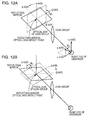
- a straight line that links both pupils of the observer is set as an x axis (or more specifically, an axial line, which is a straight line that links both pupils of the observer, and which leads from a right eye to a left eye of the observer, is set as the x axis)
- an optical axis of the right eye of the observer is set as a y axis (or more specifically, an axial line, which is orthogonal to the x axis, and which leads to a lens group side, is set as the y axis)
- a point of the reflecting mirror at which an optical axis (an optical main axis) of the lens group that configures the optical system of the image display device for the right eye, impacts upon the reflecting mirror is set as "a reflecting mirror optical axis impact point for the right eye"
- an axial line on the reflecting mirror which passes through the reflecting mirror optical axis impact point for the right eye and is parallel with the xy flat surface, is set as a ⁇ axis
- an axial line on the reflecting mirror which passes through the reflecting mirror optical axis impact point for the right eye and intersects the ⁇ axis, is set as an ⁇ axis (refer to Fig. 11 ).
- a state after the rotation of the reflecting mirror and the axial line is shown by the solid line and the dotted line in Fig.
- the image forming device and the optical system of the image display device for the left eye is disposed in mirror symmetry with the image forming device and the optical system of the image display device for the right eye with respect to a hypothetical flat surface which passes through a central point of a line segment that links both pupils of the observer and is parallel to a yz flat surface.
- an axial line that is orthogonal to the ⁇ axis and the ⁇ axis is set as a ⁇ axis
- an example of a relationship between an angle ⁇ 3 that is formed by a line ⁇ ' axis and the y axis when the ⁇ axis is projected in the xy flat surface, the angle ⁇ 1 and angle ⁇ 2 will be described below in Table 1.
- an angle in a (-x, y) quadrant is set as a positive value (refer to Fig. 11 and Fig. 12A ). It is preferable that the optical axis (the optical main axis) of the lens group intersect the center of the pupil of the observer.
- the image forming device is curved along the lines of the side surface of a cylinder as an example.
- the degree of curvature of the image forming device is expressed as an average curvature radius
- the average curvature radius may be constant or may change.
- a display apparatus that is provided with image display devices in which the degrees of curvature of the image forming device differ may be prepared, and a suitable display apparatus may be provided depending on the visual acuity of an observer, or a configuration and structure in which it is possible to change the degree of curvature of the image forming device may be used.
- a relationship between the radius of the side surface of the cylinder when it is assumed that the image forming device is curved along the lines of a side surface of a cylinder, and a dioptre value is shown in Table 2 below, but is not limited to this. [Table 2] Dioptre Value Radius of Cylinder Side Surface -3 59 mm -2 68 mm -1 80 mm 0 100 mm
- Embodiment 1 relates to a display apparatus of the present disclosure and an image display device of the present disclosure.
- a perspective view of the main portions of a display apparatus when an observer has the display apparatus equipped is shown in Fig. 1
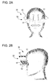
- a perspective view of the main portions of a display apparatus viewing an observer who has the display apparatus equipped, from the front is shown in Fig. 2A
- a perspective view of the main portions of the display apparatus viewing an observer who has the display apparatus equipped, from the side is shown in Fig. 2B .
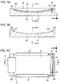
- schematic cross-sectional views of a support member and an image forming device are shown in Fig. 3A and Fig. 4A
- schematic cross-sectional views of the support member are shown in Fig. 3B and Fig.
- FIG. 4B a schematic plan view of the support member and the image forming device is shown in Fig. 3C .
- Fig. 3A and Fig. 3B are schematic cross-sectional views along an arrow A-A in Fig. 3C
- Fig. 4A and Fig. 4B are schematic cross-sectional views along an arrow A'-A' in Fig. 3A and an arrow B'-B' in Fig. 3B
- an oblique perspective view of a portion of the display apparatus of Embodiment 1 is shown in Fig. 7 , but the reflecting mirror and image forming device have been omitted from the drawing in Fig. 7 .
- a bottom view, a top view, a right side view and a rear view of the display apparatus of Embodiment 1 are shown in Fig. 8A, Fig. 8B, Fig. 8C and Fig. 8D , but in order to simplify the drawings, portions of the constituent components of the image forming device and the display apparatus have been omitted from the drawing.
- the display apparatus of Embodiment 1 is provided with
- the frame 20 in the display apparatus of Embodiment 1 is mounted on a head portion of the observer 10, and more specifically, the display apparatus of Embodiment 1 is a head mounted device (HMD).
- HMD head mounted device
- a direction of the support member 60 1 that corresponds to a first direction of an image is set as an X direction
- a direction of the support member 60 1 that corresponds to a second direction of the image is set as a Y direction
- a support surface of the support member 60 1 that supports the image forming device 40 is curved along the X direction, the Y direction or the X direction and the Y direction (or more specifically, is curved along the X direction in Embodiment 1), and therefore, the image forming device 40 is curved. More specifically, the image forming device 40 is curved along the lines of the support surface of the support member 60 1 .
- the external shape of the image is curved along the lines of the support surface of the support member 60 1 .
- the degree of curvature along the X direction of a support surface 61 of the support member 60 1 is greater than the degree of curvature along the Y direction. That is, when the degree of curvature is expressed as an average curvature radius, the average curvature radius along the X direction of the support surface of the support member is smaller than the average curvature radius along the Y direction. More specifically, the curvature radius along the X direction of the support surface of the support member is 100 mm, and the curvature radius along the Y direction is infinitely large.
- the image forming device 40 is curved along the lines of the side surface of the cylinder, and the radius of the side surface of the cylinder is 100 mm.
- an effective focal length of a lens group 52 which will be described later, is 56 mm.
- the support member 60 1 is provided with a holding member 65
- the external shape of the image forming device 40 is, as mentioned above, a rectangular shape, and an outer peripheral portion of the image forming device 40 that extends along the X direction is fixed to the support member 60 1 using the holding member 65.
- the support member 60 1 and the holding member 65 are made from aluminum.
- the upper surface and central portion of the support member 60 1 abut against the support surface 61, and outer peripheral portions 62A and 62B of the support member 60 1 that extend along the Y direction protrude from the support surface 61.
- a portion of the outer peripheral portion 62A that opposes the support surface 61 is a contact surface 62C, and one edge portion of the image forming device 40 that extends along the Y direction comes into contact with the contact surface 62C.
- an aluminum belaying member 63 is fixed to the upper surface of the support member 60 1 by a screw 64, which screws together with a screwing portion 62D, which is formed in the upper surface of the support member 60 1 , and abuts comes into contact with the other edge portion of the image forming device 40 that extends along the Y direction.
- a long hole (a long hole that is long and narrow in the X direction) through which the screw 64 is passed, is provided in the belaying member 63.
- the image forming device 40 receives a compressive force in the direction of the arrow "a" in Fig. 3A , and as a result of this, the image forming device 40, the image forming device 40 is curved without interval along the lines of the support surface 61 of the support member 60 1 .
- One end portion 65A of the holding member 65 holds the outer peripheral portion of the image forming device 40 that extends along the X direction, in place, another end portion 65B of the holding member 65 engages with the bottom surface of the support member 60 1 that extends along the X direction, and as a result of this, the outer peripheral portion of the image forming device 40 that extends along the X direction is fixed to the support member 60 1 by the holding member 65.
- a lower surface of the image forming device 40 and the support surface 61 of the support member 60 1 may be fixed together using an adhesive, and in this case, it is possible to omit the holding member 65.
- wiring 41 extends from the outer peripheral portion of the image forming device 40 that extends along the Y direction to the outside.
- a connecting portion that is provided in the outer peripheral portion of the image forming device 40 and the wiring 41 may be connected on the basis of a well-known method.
- Fig. 3C shows a state in which the wiring 41 extends from one of the outer peripheral portions of the image forming device 40 that extends along the Y direction, but the wiring 41 may extend from both of the outer peripheral portions of the image forming device 40 that extend along the Y direction.
- the image forming device 40 is configured from an organic electroluminescence display device (organic EL display device) that has a well-known configuration and structure. Additionally, the organic EL display device is configured from a first substrate, a second substrate, and a plurality of light-emitting portions that are interposed between the first substrate and the second substrate.
- the thickness of the image forming device 40 is a thickness that can be curved without interval along the lines of the support surface of the support member 60 1 , and for example, is 0.5 mm or less, and is for example, from 0.2 mm to 0.5 mm.
- the number of pixels is set as 1920 x 1080.
- the display apparatus of Embodiment 1 is provided with an image display device for the left eye 30L and an image display device for the right eye 30R.
- a horizontal viewing angle (a viewing angle of a single eye) in each image display device 30 is set as 100°
- an overlap (a viewing angle of both eyes) between a horizontal field of view in the image display device for the left eye 30L and a horizontal field of view in the image display device for the right eye 30R is set as 70°
- a total horizontal viewing angle is set as 130°.
- a length L x along the X direction of the display region of each the image forming device 40 is set as 100 mm.
- a vertical viewing angle is set as 44°.
- the mass of the lens group in this case is set as "1"
- the viewing angle of both eyes is set as 70°
- the total horizontal viewing angle is set as 170°
- the length L x of the display region of each image forming device 40 is set as 126 mm
- the mass of the lens group becomes "4.6”
- the effective focal length thereof becomes 67.2 mm.
- the frame 20 that is mounted on the head portion of the observer 10 is made from plastic, and is formed from a front portion 21 that is disposed in front of the observer 10, and a side portion 22 that extends from the end portion of the front portion.
- a hole portion 22A is provided in a back end portion of the side portion 22, and by passing a belt through the hole portion 22A, and wrapping the belt around a rear portion of the head portion of the observer, it is possible to mount the frame 20 on the head portion of the observer 10.
- An arm 23A extends upward from an upper portion of the front portion 21, and a forehead rest 23B that abuts against the forehead of the observer 10 is attached to a leading end portion of the arm 23A.
- a nose pad portion 24 is arranged in the front portion 21.
- a back portion of a retaining member 25 is attached to a lower end portion of the front portion 21, and a base portion 26 is attached to a front portion of the retaining member 25.
- a pupil/optical system inter-distance adjustment device 80 which will be described later, is attached to a leading end portion of the base portion 26, and a pedestal 71 that configures the pupil/optical system inter-distance adjustment device 80 is disposed above the base portion 26 so as to be freely slidable in an anteroposterior direction.
- An optical system 50L that configures the image display device for the left eye 30L is stored in a housing 53L
- an optical system 50R that configures the image display device for the right eye 30R is stored in a housing 53R.
- the image display device for the left eye 30L is attached to the housing 53L and the image display device for the right eye 30R is attached to the housing 53R.
- the housing 53L and the housing 53R are attached to the pedestal 71.
- the optical system 50L and the image display device for the left eye 30L, and the optical system 50R and the image display device for the right eye 30R are respectively disposed on the pedestal 71 so as to be freely slidable in a horizontal direction independent of one another.
- the "anteroposterior direction” refers to a direction in which the lens group becomes closer to or further away from the pupil
- the "horizontal direction” refers to a direction in which the image display device for the left eye and the image display device for the right eye become mutually closer to or further away from one another.
- the optical system 50 is formed from a reflecting mirror 51 that reflects an image from the image forming device 40 and the lens group 52 into which an image that is reflected by the reflecting mirror 51, is input.
- a reflecting mirror 51R and a lens group 52R that configure the image display device for the right eye are attached to the pedestal 71 via the housing 53R, and are capable of sliding on the base portion 26 in the horizontal direction.
- a reflecting mirror 51L and a lens group 52L that configure the image display device for the left eye are attached to the pedestal 71 via the housing 53L, and are capable of sliding on the base portion 26 in the horizontal direction.
- the lens groups 52 (52R and 52L) are disposed between the pupils of the observer 10 and the reflecting mirrors 51 (51R and 51L), the image forming devices 40 are disposed above the reflecting mirrors 51.
- the lens group 52 is formed to have one group and 3 lenses, a second lens thereof has a negative power, and a refractive index of a material that configures the second lens is greater than a refractive index of a material that configures a first lens and a third lens thereof.
- the first lens and the third lens have a positive power.
- the second lens is a meniscus lens. More specifically, the effective focal length of the lens group 52 is set as 56.01 mm, a back focal length is set as 44.64 mm, a front focal length is set as -32.16 mm, and an F number is set as 14.0.
- a length of the lens group 52 in a horizontal direction is set as 36 mm, and a length thereof in the vertical direction is set as 20 mm.
- the specifications of the first lens (the lens that is closest to the pupil), the second lens, and the third lens (the lens that is closest to the reflecting mirror) are shown in Table 4 below, but the lenses are not limited to such specifications. It is preferable that a configuration in which the lens group 52 is a telecentric optical system, or more specifically, in which a reflecting mirror side is a telecentric optical system, be used. A distance between the first lens and the pupil (pupil diameter: 4 mm) of the observer 10 is set as 10 mm. Additionally, when the mass of this lens group is set as "1", the mass of a lens group in which the distance between the first lens and the pupil of the observer 10 is set as 12 mm becomes "1.7".
- Fig. 9A Ways in which an image from the image forming device 40 is imaged by various lens groups are shown in Fig. 9A, Fig. 9B and Fig. 9C , but the lens group that is shown in Fig. 9A is a lens group of telecentric optical system, Fig. 9B is a lens group of configuration that is close to a telecentric optical system, and Fig. 9C is a normal lens group.
- the lens group that is shown in Fig. 9A was used.
- the display apparatus of Embodiment 1 is further provided with an image display device inter-distance adjustment device 70 that adjusts a distance between the image display device for the left eye 30L and the image display device for the right eye 30R.
- the image display device inter-distance adjustment device 70 is configured from the pedestal 71, a screw feeding mechanism 73 that is attached to a side surface 72 that is positioned on an outer side of the pedestal 71, a tapped hole 75A for fixing the housing 53 to the pedestal 71 from the bottom using a retaining force in a slidable manner, guiding grooves 74B and 76B that are provided in the housing 53, a guiding groove 75B that is provided in the pedestal 71 and pins 74A and 76A that are provided in the pedestal 71, and engage with the guiding grooves 74B and 76B.
- the guiding grooves 75B, 75B and 76B extend in the horizontal direction. Further, when the screw feeding mechanism 73 is rotated, the housing 53 (the housing 53L or the housing 53R) moves in the horizontal direction with respect to the base portion 26. The movement of the housing 53 is reliably performed in the horizontal direction due to the engagement of the pin 74A, the tapped hole 75A, and the pin 76A with the guiding grooves 74B, 75B and 76B. A movement distance of the housing 53L and 53R in the horizontal direction is set as ⁇ 5 mm. In this manner, by providing the display apparatus with the image display device inter-distance adjustment device 70, use by observers for whom the distance between the pupils differs is made easy.
- the housing 53R and 53L extend further upward than is shown in Fig. 8A, 8B, 8C and 8D , and the support member 60 1 that supports the image forming device 40 is attached to this portion of the housing 53R and 53L that extends upward, but these portions have been omitted from the drawings.
- the display apparatus of Embodiment 1 is provided with the pupil/optical system inter-distance adjustment device 80 that adjusts a distance between the pupil of the observer 10 and the lens group 52. More specifically, the pupil/optical system inter-distance adjustment device 80 is configured from a side wall 82 that is attached to a leading end portion of a second retaining member 26, a screw feeding mechanism 83 that is attached to the side wall 82, a key 27A that is provided in the pedestal 71, and extends downward from the pedestal 71, a guiding groove 27B that is provided in the base portion 26 and engages with the key 27A, and a fastening portion 27C that retains the pedestal 71 with respect to the base portion 26 at a level at which the pedestal 71 is movable.
- the pedestal 71 moves in the anteroposterior direction with respect to the base portion 26.
- the movement of the pedestal 71 is reliably performed in the anteroposterior direction due to the engagement of the key 27A with the guiding groove 27B.
- a movement distance of the pedestal 71 in the anteroposterior direction is set as ⁇ 4 mm.
- the display apparatus or the image display device of Embodiment 1 is provided with a support member in which the support surface is curved along the X direction, it is possible to cause the image forming device to be curved on the basis of a simple configuration and structure. More specifically, it is possible to cause the image forming device to be curved along the lines of the support surface of the support member. Further, since the image forming device is curved, it is possible achieve a wide viewing angle while achieving an effect of being able to reduce an optical path length difference between an optical path length of light that is output from a central portion of the image forming device and an optical path length of light that is output from an outer edge portion of the image forming device, and for example, suppressing an increase in the size of the lens group that configures the optical system.
- Embodiment 2 is a modification example of Embodiment 1.
- a schematic cross-sectional view of a support member and an image forming device that configure a display apparatus or an image display device of Embodiment 2 is shown in Fig. 5A
- a schematic cross-sectional view of the support member is shown in Fig. 5B
- a schematic plan view of the support member and the image forming device is shown in Fig. 5C
- a schematic cross-sectional view along an arrow D-D in Fig. 5A is shown in Fig. 5D .
- the outer peripheral portion of the image forming device 40 that extends along the X direction is interposed by a support member 60 2 .
- the support member 60 2 is formed from a lower side member 66A and an upper side member 66B, a kind of forehead edge member is configured by combining the lower side member 66A and the upper side member 66B, and a groove portion 66C is formed on an inside side surface of the support member 60 2 . Further, an outer peripheral portion of the image forming device 40 that extends along the X direction interlocks with the groove portion 66C.
- the lower side member 66A and the upper side member 66B may be fixed to one another using a screw (not shown in the drawings), or may be fixed to one another using an adhesive. It is preferable that the outer peripheral portion of the image forming device 40 that extends along the X direction be fixed to the groove portion 66C using an adhesive. Additionally, in the example that is shown in the drawings, in addition to the outer peripheral portion of the image forming device 40 that extends along the X direction, the outer peripheral portion of the image forming device 40 that extends along the Y direction is also interposed by the support member 60 2 , but only the outer peripheral portion of the image forming device 40 that extends along the X direction may be interposed by the support member 60 2 . In this case, it is desirable that the outer peripheral portion of the image forming device 40 that extends along the Y direction be fixed to the support member 60 2 using an adhesive.
- the configuration and structure of the display apparatus or the image display device of Embodiment 2 is the same as the configuration and structure of the display apparatus or the image display device of Embodiment 1, detailed description thereof has been omitted.
- Embodiment 3 is a modification example of Embodiment 2.
- the image forming device 40 is curved.
- the degree of curvature can be changed.
- a schematic cross-sectional view of a support member and an image forming device that configure a display apparatus or an image display device of Embodiment 3 is shown in Fig. 6A
- a schematic plan view of the support member and the image forming device is shown in Fig. 6B .
- Embodiment 3 there is a gap between the groove portion 66C and the outer peripheral portion of the image forming device 40 that extends along the X direction. Further, a protruding portion 67A and a screwing portion 67B are provided on a side surface that extends along the X direction of a support member 60 3 .
- the support member 60 3 is stored in a housing (not shown in the drawings), the upper portion of which is open. The housing is attached to the upper portions of the housing 53R and 53L. A hole portion that engages with the protruding portion 67A is formed on a side surface of the housing.
- a guiding groove and extends substantially up and down is formed on a portion of the side surface of the housing opposing the screwing portion 67B, and it is possible to fix the support member 60 3 to the side surface of the housing by inserting a screw into the guiding groove, and screwing the screw together with the screwing portion 67B.
- a force that is applied to the X direction of the support member 60 3 and the image forming device 40 changes.
- Fig. 6A the center of the protruding portion 67A is shown with a cross.
- a trajectory of a circle of the screwing portion 67B that has the center of the protruding portion 67A as the center thereof is shown by the dotted line "a"
- a trajectory of the center of a through hole is shown by the solid line "b”.
- the gap may be filled in with a suitable material (for example, a shim). Alternatively, an elastic material may be tucked into the gap in advance.
- a force that is applied to the X direction of the support member 60 3 and the image forming device 40 may be changed using a push screw 68B for moving a push member 68A and a push member 68A in the X direction.
- the present disclosure has been described above on the basis of preferable embodiments, but the present disclosure is not limited to these embodiments.
- the configuration and structure of the image display device and the image forming device that are described in the embodiments are examples, and it is possible to modify the embodiments as appropriate. It is possible to configure a projector by combining the image forming device and the support member that supports the image forming device that are described in the embodiments. Depending on the circumstances, as shown in Fig.
- the image display device is provided with a single image forming device (indicated by 40R and 40L), an optical system that respectively guides an image from the image forming device to a pupil of a right side and a pupil of a left side of an observer, and a support member (not shown in the drawings) that supports the image forming device, and in this case, for example, it is possible to configure the optical system from at least a reflecting mirror 51L and a lens group 52L for the left eye, and a reflecting mirror 51R and a lens group 52R for the right eye.
- An image display device that is provided with
Landscapes
- Physics & Mathematics (AREA)
- General Physics & Mathematics (AREA)
- Optics & Photonics (AREA)
Applications Claiming Priority (2)
| Application Number | Priority Date | Filing Date | Title |
|---|---|---|---|
| JP2013082828 | 2013-04-11 | ||
| PCT/JP2014/058605 WO2014168010A1 (fr) | 2013-04-11 | 2014-03-26 | Dispositif d'affichage d'image et dispositif d'affichage |
Publications (2)
| Publication Number | Publication Date |
|---|---|
| EP2985652A1 true EP2985652A1 (fr) | 2016-02-17 |
| EP2985652A4 EP2985652A4 (fr) | 2016-12-14 |
Family
ID=51689422
Family Applications (1)
| Application Number | Title | Priority Date | Filing Date |
|---|---|---|---|
| EP14783184.6A Withdrawn EP2985652A4 (fr) | 2013-04-11 | 2014-03-26 | Dispositif d'affichage d'image et dispositif d'affichage |
Country Status (5)
| Country | Link |
|---|---|
| US (1) | US10663736B2 (fr) |
| EP (1) | EP2985652A4 (fr) |
| JP (1) | JP6547622B2 (fr) |
| CN (1) | CN104583842B (fr) |
| WO (1) | WO2014168010A1 (fr) |
Cited By (1)
| Publication number | Priority date | Publication date | Assignee | Title |
|---|---|---|---|---|
| WO2018116946A1 (fr) * | 2016-12-19 | 2018-06-28 | Sharp Kabushiki Kaisha | Appareil permettant d'obtenir un visiocasque compact avec des réflecteurs et un élément oculaire |
Families Citing this family (25)
| Publication number | Priority date | Publication date | Assignee | Title |
|---|---|---|---|---|
| JP5499854B2 (ja) | 2010-04-08 | 2014-05-21 | ソニー株式会社 | 頭部装着型ディスプレイにおける光学的位置調整方法 |
| JP5434848B2 (ja) | 2010-08-18 | 2014-03-05 | ソニー株式会社 | 表示装置 |
| JP5780129B2 (ja) | 2011-11-22 | 2015-09-16 | ソニー株式会社 | 光ビーム伸長装置、画像表示装置及び光学装置 |
| JP5879973B2 (ja) | 2011-11-30 | 2016-03-08 | ソニー株式会社 | 光反射部材、光ビーム伸長装置、画像表示装置及び光学装置 |
| EP2808725B1 (fr) | 2012-01-24 | 2018-09-26 | Sony Corporation | Dispositif d'affichage monté sur la tête avec élément pare-lumière |
| JP6145966B2 (ja) | 2012-05-09 | 2017-06-14 | ソニー株式会社 | 表示装置 |
| CN104204905B (zh) | 2013-01-10 | 2016-11-23 | 索尼公司 | 图像显示设备、图像生成装置以及透射式空间光调制装置 |
| JP6123342B2 (ja) | 2013-02-20 | 2017-05-10 | ソニー株式会社 | 表示装置 |
| US10527859B2 (en) | 2013-04-11 | 2020-01-07 | Sony Corporation | Image display device and display apparatus |
| JP6367529B2 (ja) | 2013-06-25 | 2018-08-01 | ソニー株式会社 | 表示装置、表示制御方法、表示制御装置、および電子機器 |
| WO2015001839A1 (fr) | 2013-07-04 | 2015-01-08 | ソニー株式会社 | Dispositif d'affichage |
| US9952435B2 (en) | 2013-07-16 | 2018-04-24 | Sony Corporation | Display apparatus having curved image forming apparatus |
| WO2015008530A1 (fr) | 2013-07-16 | 2015-01-22 | ソニー株式会社 | Dispositif d'affichage |
| JP6314518B2 (ja) | 2014-02-10 | 2018-04-25 | ソニー株式会社 | 画像表示装置及び表示装置 |
| JP2015148782A (ja) | 2014-02-10 | 2015-08-20 | ソニー株式会社 | 画像表示装置及び表示装置 |
| JP6201836B2 (ja) | 2014-03-14 | 2017-09-27 | ソニー株式会社 | 光学装置及びその組立方法、ホログラム回折格子、表示装置並びにアライメント装置 |
| JP6391952B2 (ja) | 2014-03-17 | 2018-09-19 | ソニー株式会社 | 表示装置及び光学装置 |
| JP2015184560A (ja) | 2014-03-25 | 2015-10-22 | ソニー株式会社 | 導光装置、画像表示装置及び表示装置 |
| JP2015184561A (ja) | 2014-03-25 | 2015-10-22 | ソニー株式会社 | 導光装置、画像表示装置及び表示装置 |
| JP6780502B2 (ja) | 2014-08-18 | 2020-11-04 | ソニー株式会社 | 画像表示装置及び表示装置 |
| EP3264748B1 (fr) * | 2015-02-27 | 2020-07-08 | Sony Interactive Entertainment Inc. | Visiocasque |
| WO2018163035A1 (fr) * | 2017-03-08 | 2018-09-13 | 3M Innovative Properties Company | Système optique |
| CN107861247B (zh) * | 2017-12-22 | 2020-08-25 | 联想(北京)有限公司 | 光学部件及增强现实设备 |
| CN109031593B (zh) * | 2018-08-03 | 2021-02-23 | 诚瑞光学(苏州)有限公司 | 投影镜头 |
| WO2020257713A1 (fr) * | 2019-06-20 | 2020-12-24 | Firefly Dimension Inc. | Système, appareil et système de réalité augmentée monté sur la tête |
Family Cites Families (106)
| Publication number | Priority date | Publication date | Assignee | Title |
|---|---|---|---|---|
| JPS62105184A (ja) * | 1985-10-31 | 1987-05-15 | 日本精機株式会社 | 液晶表示装置 |
| JPH05134208A (ja) | 1991-11-12 | 1993-05-28 | Olympus Optical Co Ltd | 像観察装置 |
| US5486841A (en) * | 1992-06-17 | 1996-01-23 | Sony Corporation | Glasses type display apparatus |
| JP2795779B2 (ja) * | 1992-06-19 | 1998-09-10 | シャープ株式会社 | ディスプレイ・パネル |
| US5473365A (en) | 1992-12-25 | 1995-12-05 | Olympus Optical Co., Ltd. | Head-mounted image display apparatus in which a system is capable of changing aspect ratio of observed image |
| JPH06194598A (ja) | 1992-12-25 | 1994-07-15 | Olympus Optical Co Ltd | 頭部装着型ディスプレイ装置 |
| JP3245478B2 (ja) * | 1993-04-27 | 2002-01-15 | オリンパス光学工業株式会社 | 頭部装着式表示装置 |
| JP3263062B2 (ja) | 1993-04-27 | 2002-03-04 | オリンパス光学工業株式会社 | 視覚表示装置 |
| JPH0772420A (ja) * | 1993-09-03 | 1995-03-17 | Casio Comput Co Ltd | 画像表示装置 |
| JP3328028B2 (ja) | 1993-10-19 | 2002-09-24 | オリンパス光学工業株式会社 | 頭部装着型映像表示装置 |
| US5793339A (en) | 1993-11-11 | 1998-08-11 | Olympus Optical Co., Ltd. | Visual display apparatus |
| GB9403925D0 (en) | 1994-03-01 | 1994-04-20 | Virtuality Entertainment Ltd | Optical system |
| EP0679919B1 (fr) | 1994-04-21 | 2000-07-12 | Sega Enterprises, Ltd. | Affichage monté sur la tête |
| JPH07318850A (ja) | 1994-05-23 | 1995-12-08 | Olympus Optical Co Ltd | 頭部装着型映像表示装置 |
| WO1996000406A1 (fr) | 1994-06-23 | 1996-01-04 | Seiko Epson Corporation | Dispositif de presentation monte sur des lunettes |
| JPH08166557A (ja) | 1994-06-23 | 1996-06-25 | Seiko Epson Corp | 頭部装着型表示装置 |
| JPH0882762A (ja) * | 1994-07-15 | 1996-03-26 | Sega Enterp Ltd | 頭部搭載型映像表示装置およびこれを用いた映像表示システム |
| JPH08191462A (ja) | 1995-01-10 | 1996-07-23 | Olympus Optical Co Ltd | 立体映像再生装置および立体撮影装置 |
| WO1996028756A1 (fr) * | 1995-03-09 | 1996-09-19 | Geo-Centers, Inc. | Substrat conducteur, dispositif a cristaux liquides fabrique a partir de celui-ci, et composition cristalline liquide en contact avec ce substrat |
| JP3286133B2 (ja) | 1995-11-09 | 2002-05-27 | シャープ株式会社 | 拡大用レンズとディスプレイ装置 |
| JPH0949999A (ja) * | 1995-12-29 | 1997-02-18 | Fujiyama Teruki | ディスプレイ装置 |
| TW395121B (en) * | 1996-02-26 | 2000-06-21 | Seiko Epson Corp | Personal wearing information display device and the display method using such device |
| JPH10104548A (ja) | 1996-09-27 | 1998-04-24 | Nikon Corp | ヘッドマウントディスプレイ装置 |
| JPH10206786A (ja) * | 1997-01-17 | 1998-08-07 | Sanyo Electric Co Ltd | 頭部装着型の画像表示装置 |
| JPH10260357A (ja) * | 1997-03-18 | 1998-09-29 | Olympus Optical Co Ltd | 偏心プリズム光学系 |
| US5983073A (en) * | 1997-04-04 | 1999-11-09 | Ditzik; Richard J. | Modular notebook and PDA computer systems for personal computing and wireless communications |
| US6100862A (en) | 1998-04-20 | 2000-08-08 | Dimensional Media Associates, Inc. | Multi-planar volumetric display system and method of operation |
| JP2002049021A (ja) | 2000-08-03 | 2002-02-15 | Seiko Instruments Inc | 腕携帯情報機器 |
| US6529331B2 (en) * | 2001-04-20 | 2003-03-04 | Johns Hopkins University | Head mounted display with full field of view and high resolution |
| JP4784001B2 (ja) * | 2001-05-18 | 2011-09-28 | コニカミノルタホールディングス株式会社 | 表示パネル及び該パネルを備えた曲面型表示装置 |
| US6522474B2 (en) * | 2001-06-11 | 2003-02-18 | Eastman Kodak Company | Head-mounted optical apparatus for stereoscopic display |
| US7114500B2 (en) | 2001-08-28 | 2006-10-03 | Marctec, Llc | Surgical draping system |
| WO2004049050A1 (fr) * | 2002-11-22 | 2004-06-10 | Koninklijke Philips Electronics N.V. | Procede de fabrication d'un dispositif d'affichage incurve |
| WO2004061519A1 (fr) | 2002-12-24 | 2004-07-22 | Nikon Corporation | Casque de visualisation |
| JP2004233867A (ja) | 2003-01-31 | 2004-08-19 | Nikon Corp | 画像表示装置 |
| CN100416340C (zh) | 2003-04-25 | 2008-09-03 | 微型光学公司 | 双目镜观察系统 |
| US6879443B2 (en) | 2003-04-25 | 2005-04-12 | The Microoptical Corporation | Binocular viewing system |
| US7495638B2 (en) * | 2003-05-13 | 2009-02-24 | Research Triangle Institute | Visual display with increased field of view |
| DE50305854D1 (de) * | 2003-09-03 | 2007-01-11 | Zeiss Carl | HMD-Vorrichtung (Head Mounted Display) mit einer eine asphärische Fläche aufweisenden Abbildungsoptik |
| JP2004139132A (ja) | 2004-01-08 | 2004-05-13 | Seiko Epson Corp | 画像表示装置及び頭部装着型表示装置 |
| GB2413717A (en) * | 2004-04-28 | 2005-11-02 | Graeme Donald Robertson | A spherical visual display |
| US20060056069A1 (en) * | 2004-09-10 | 2006-03-16 | Premier Image Technology Corporation | Photographic lens with fixed focal length |
| JP4933056B2 (ja) * | 2005-05-11 | 2012-05-16 | キヤノン株式会社 | 画像表示装置及びそれを用いた撮像装置 |
| JP2007086500A (ja) | 2005-09-22 | 2007-04-05 | Sony Corp | 表示装置 |
| IL172797A (en) | 2005-12-25 | 2012-09-24 | Elbit Systems Ltd | Real-time image scanning and processing |
| EP1826604B1 (fr) * | 2006-01-31 | 2015-12-23 | Semiconductor Energy Laboratory Co., Ltd. | Dispositif d'affichage |
| JP5074777B2 (ja) | 2006-05-22 | 2012-11-14 | キヤノン株式会社 | 撮像機能付表示装置、画像処理装置、画像処理方法、および、画像表示システム |
| US8035576B2 (en) | 2007-02-20 | 2011-10-11 | Canon Kabushiki Kaisha | Head-mounted display and head-mounted video display |
| JP2008224850A (ja) | 2007-03-09 | 2008-09-25 | Shimadzu Corp | 表示装置 |
| JP5094250B2 (ja) * | 2007-07-10 | 2012-12-12 | 株式会社ジャパンディスプレイイースト | 表示装置 |
| JP2009134276A (ja) * | 2007-11-05 | 2009-06-18 | Panasonic Corp | 表示装置、表示方法、表示プログラム、集積回路、眼鏡型ヘッドマウントディスプレイ、自動車、単眼鏡、及び据置型ディスプレイ |
| JP2009128565A (ja) | 2007-11-22 | 2009-06-11 | Toshiba Corp | 表示装置、表示方法及びヘッドアップディスプレイ |
| US7988313B2 (en) * | 2008-03-20 | 2011-08-02 | Kutnyak Mark R | Illuminated headgear |
| JP2010039441A (ja) | 2008-08-08 | 2010-02-18 | Hitachi Displays Ltd | 液晶表示装置 |
| JP2010072502A (ja) | 2008-09-22 | 2010-04-02 | Hitachi Displays Ltd | 液晶表示装置 |
| JP5388534B2 (ja) | 2008-10-09 | 2014-01-15 | キヤノン株式会社 | 画像処理装置およびその方法、頭部装着型ディスプレイ、プログラム、記録媒体 |
| JP5321011B2 (ja) | 2008-11-25 | 2013-10-23 | ソニー株式会社 | 画像信号処理装置、画像信号処理方法および画像投射装置 |
| JP5191920B2 (ja) | 2009-02-04 | 2013-05-08 | 株式会社ジャパンディスプレイイースト | 液晶表示装置 |
| US8004769B2 (en) | 2009-03-05 | 2011-08-23 | Nabes, Llc | Binocular apparatus and system |
| EP2244117B1 (fr) | 2009-04-24 | 2017-05-31 | Ricoh Company, Ltd. | Objectif à focale variable |
| US20120212484A1 (en) | 2010-02-28 | 2012-08-23 | Osterhout Group, Inc. | System and method for display content placement using distance and location information |
| JP5678460B2 (ja) | 2010-04-06 | 2015-03-04 | ソニー株式会社 | 頭部装着型ディスプレイ |
| JP5494153B2 (ja) | 2010-04-08 | 2014-05-14 | ソニー株式会社 | 頭部装着型ディスプレイにおける画像表示方法 |
| JP5499854B2 (ja) | 2010-04-08 | 2014-05-21 | ソニー株式会社 | 頭部装着型ディスプレイにおける光学的位置調整方法 |
| JP5434848B2 (ja) | 2010-08-18 | 2014-03-05 | ソニー株式会社 | 表示装置 |
| JP2012079291A (ja) | 2010-09-08 | 2012-04-19 | Namco Bandai Games Inc | プログラム、情報記憶媒体及び画像生成システム |
| JP2012063633A (ja) | 2010-09-16 | 2012-03-29 | Olympus Corp | 頭部装着型表示装置 |
| JP5598281B2 (ja) | 2010-11-19 | 2014-10-01 | ソニー株式会社 | 投射型表示システム |
| JP6246592B2 (ja) * | 2010-12-16 | 2017-12-13 | ロッキード マーティン コーポレーション | 画素レンズを有するコリメーティングディスプレイ |
| US8743463B2 (en) | 2011-02-04 | 2014-06-03 | Seiko Epson Corporation | Virtual image display |
| JP5655626B2 (ja) | 2011-02-24 | 2015-01-21 | ソニー株式会社 | 画像処理装置、および画像処理方法、並びにプログラム |
| JP5121962B2 (ja) * | 2011-03-31 | 2013-01-16 | 株式会社東芝 | 電子機器 |
| JP6180405B2 (ja) * | 2011-05-03 | 2017-08-16 | エンドーシー コーポレイションEndosee Corporation | ヒステロスコピー及び子宮内膜生検用の方法及び装置 |
| US20150077312A1 (en) | 2011-05-13 | 2015-03-19 | Google Inc. | Near-to-eye display having adaptive optics |
| TW201300838A (zh) | 2011-06-28 | 2013-01-01 | Era Optoelectronics Inc | 浮在空中的虛擬實像顯示裝置 |
| JP5851157B2 (ja) | 2011-08-25 | 2016-02-03 | リコー光学株式会社 | 接眼レンズ系および画像観察装置 |
| JP5780129B2 (ja) | 2011-11-22 | 2015-09-16 | ソニー株式会社 | 光ビーム伸長装置、画像表示装置及び光学装置 |
| WO2013076994A1 (fr) * | 2011-11-24 | 2013-05-30 | パナソニック株式会社 | Dispositif d'affichage monté sur tête |
| JP5879973B2 (ja) | 2011-11-30 | 2016-03-08 | ソニー株式会社 | 光反射部材、光ビーム伸長装置、画像表示装置及び光学装置 |
| US9459457B2 (en) | 2011-12-01 | 2016-10-04 | Seebright Inc. | Head mounted display with remote control |
| EP2808725B1 (fr) | 2012-01-24 | 2018-09-26 | Sony Corporation | Dispositif d'affichage monté sur la tête avec élément pare-lumière |
| JP6035793B2 (ja) | 2012-03-14 | 2016-11-30 | ソニー株式会社 | 画像表示装置及び画像生成装置 |
| JP5990998B2 (ja) | 2012-04-23 | 2016-09-14 | セイコーエプソン株式会社 | 虚像表示装置 |
| JP6145966B2 (ja) | 2012-05-09 | 2017-06-14 | ソニー株式会社 | 表示装置 |
| KR102041883B1 (ko) * | 2012-07-09 | 2019-11-08 | 삼성디스플레이 주식회사 | 커브드 프레임 및 이를 갖는 커브드 표시장치 |
| US9250445B2 (en) | 2012-08-08 | 2016-02-02 | Carol Ann Tosaya | Multiple-pixel-beam retinal displays |
| US20140104692A1 (en) | 2012-10-11 | 2014-04-17 | Sony Computer Entertainment Europe Limited | Head mountable display |
| CN102910127A (zh) | 2012-11-20 | 2013-02-06 | 刘仁国 | Gps雷达道路情况数据信息平视显示方法 |
| CN104204905B (zh) | 2013-01-10 | 2016-11-23 | 索尼公司 | 图像显示设备、图像生成装置以及透射式空间光调制装置 |
| JP6123342B2 (ja) | 2013-02-20 | 2017-05-10 | ソニー株式会社 | 表示装置 |
| US10527859B2 (en) * | 2013-04-11 | 2020-01-07 | Sony Corporation | Image display device and display apparatus |
| US9470919B2 (en) | 2013-05-14 | 2016-10-18 | Microsoft Technology Licensing, Llc | Methods for producing a glass-based non planar digital display |
| JP2014225725A (ja) | 2013-05-15 | 2014-12-04 | ソニー株式会社 | 表示装置及び画像表示装置用光源 |
| JP6367529B2 (ja) | 2013-06-25 | 2018-08-01 | ソニー株式会社 | 表示装置、表示制御方法、表示制御装置、および電子機器 |
| WO2015001839A1 (fr) | 2013-07-04 | 2015-01-08 | ソニー株式会社 | Dispositif d'affichage |
| US9952435B2 (en) | 2013-07-16 | 2018-04-24 | Sony Corporation | Display apparatus having curved image forming apparatus |
| WO2015008530A1 (fr) * | 2013-07-16 | 2015-01-22 | ソニー株式会社 | Dispositif d'affichage |
| JP2015052635A (ja) | 2013-09-05 | 2015-03-19 | ソニー株式会社 | 光学ユニット、撮像装置 |
| JP2015148782A (ja) | 2014-02-10 | 2015-08-20 | ソニー株式会社 | 画像表示装置及び表示装置 |
| JP6314518B2 (ja) | 2014-02-10 | 2018-04-25 | ソニー株式会社 | 画像表示装置及び表示装置 |
| JP6201836B2 (ja) | 2014-03-14 | 2017-09-27 | ソニー株式会社 | 光学装置及びその組立方法、ホログラム回折格子、表示装置並びにアライメント装置 |
| JP6391952B2 (ja) | 2014-03-17 | 2018-09-19 | ソニー株式会社 | 表示装置及び光学装置 |
| JP2015184560A (ja) | 2014-03-25 | 2015-10-22 | ソニー株式会社 | 導光装置、画像表示装置及び表示装置 |
| JP2015184561A (ja) | 2014-03-25 | 2015-10-22 | ソニー株式会社 | 導光装置、画像表示装置及び表示装置 |
| US10132612B2 (en) | 2015-07-30 | 2018-11-20 | Hseb Dresden Gmbh | Method and assembly for determining the thickness of a layer in a sample stack |
| US10007121B2 (en) | 2015-08-18 | 2018-06-26 | Quanta Computer Inc. | See-through head-mounted display |
-
2014
- 2014-03-26 EP EP14783184.6A patent/EP2985652A4/fr not_active Withdrawn
- 2014-03-26 WO PCT/JP2014/058605 patent/WO2014168010A1/fr not_active Ceased
- 2014-03-26 CN CN201480002217.4A patent/CN104583842B/zh not_active Expired - Fee Related
- 2014-03-26 US US14/782,054 patent/US10663736B2/en not_active Expired - Fee Related
- 2014-03-26 JP JP2015511197A patent/JP6547622B2/ja not_active Expired - Fee Related
Cited By (1)
| Publication number | Priority date | Publication date | Assignee | Title |
|---|---|---|---|---|
| WO2018116946A1 (fr) * | 2016-12-19 | 2018-06-28 | Sharp Kabushiki Kaisha | Appareil permettant d'obtenir un visiocasque compact avec des réflecteurs et un élément oculaire |
Also Published As
| Publication number | Publication date |
|---|---|
| WO2014168010A1 (fr) | 2014-10-16 |
| JP6547622B2 (ja) | 2019-07-24 |
| JPWO2014168010A1 (ja) | 2017-02-16 |
| CN104583842B (zh) | 2019-02-15 |
| EP2985652A4 (fr) | 2016-12-14 |
| US20160062123A1 (en) | 2016-03-03 |
| US10663736B2 (en) | 2020-05-26 |
| CN104583842A (zh) | 2015-04-29 |
Similar Documents
| Publication | Publication Date | Title |
|---|---|---|
| EP2985652A1 (fr) | Dispositif d'affichage d'image et dispositif d'affichage | |
| EP2985651B1 (fr) | Dispositif d'affichage d'image et dispositif d'affichage | |
| US10534172B2 (en) | Display apparatus | |
| EP3024221B1 (fr) | Dispositif d'affichage | |
| US10782453B2 (en) | Display devices with reflectors | |
| JP7392433B2 (ja) | 頭部装着型表示装置 | |
| US9915823B1 (en) | Lightguide optical combiner for head wearable display | |
| CN111381377A (zh) | 一种近眼显示设备 | |
| US10073273B2 (en) | Virtual image display apparatus | |
| CN109507803B (zh) | 虚像显示装置 | |
| JP2021086052A (ja) | 頭部装着型表示装置及び表示方法 | |
| CN211669451U (zh) | 一种近眼显示设备 | |
| CN104583840B (zh) | 图像显示装置和显示设备 | |
| CN107300767A (zh) | 头戴式可视设备 | |
| KR101797878B1 (ko) | 광축 이동 장치 및 이를 이용한 헤드 마운트 디스플레이 시스템 | |
| JP2008504585A (ja) | 装着者の瞳の間隔に合わせる調節機器を備えた眼科用ディスプレイ | |
| TW202101062A (zh) | 虛擬實境顯示裝置 |
Legal Events
| Date | Code | Title | Description |
|---|---|---|---|
| PUAI | Public reference made under article 153(3) epc to a published international application that has entered the european phase |
Free format text: ORIGINAL CODE: 0009012 |
|
| 17P | Request for examination filed |
Effective date: 20150112 |
|
| AK | Designated contracting states |
Kind code of ref document: A1 Designated state(s): AL AT BE BG CH CY CZ DE DK EE ES FI FR GB GR HR HU IE IS IT LI LT LU LV MC MK MT NL NO PL PT RO RS SE SI SK SM TR |
|
| AX | Request for extension of the european patent |
Extension state: BA ME |
|
| DAX | Request for extension of the european patent (deleted) | ||
| A4 | Supplementary search report drawn up and despatched |
Effective date: 20161114 |
|
| RIC1 | Information provided on ipc code assigned before grant |
Ipc: G02B 27/02 20060101AFI20161108BHEP Ipc: H04N 5/64 20060101ALI20161108BHEP |
|
| STAA | Information on the status of an ep patent application or granted ep patent |
Free format text: STATUS: EXAMINATION IS IN PROGRESS |
|
| 17Q | First examination report despatched |
Effective date: 20200225 |
|
| RAP3 | Party data changed (applicant data changed or rights of an application transferred) |
Owner name: SONY GROUP CORPORATION |
|
| STAA | Information on the status of an ep patent application or granted ep patent |
Free format text: STATUS: THE APPLICATION IS DEEMED TO BE WITHDRAWN |
|
| 18D | Application deemed to be withdrawn |
Effective date: 20221001 |