EP2986879B1 - Sichere flüssigkeitsverbindung - Google Patents
Sichere flüssigkeitsverbindung Download PDFInfo
- Publication number
- EP2986879B1 EP2986879B1 EP14723461.1A EP14723461A EP2986879B1 EP 2986879 B1 EP2986879 B1 EP 2986879B1 EP 14723461 A EP14723461 A EP 14723461A EP 2986879 B1 EP2986879 B1 EP 2986879B1
- Authority
- EP
- European Patent Office
- Prior art keywords
- locking device
- plug
- secondary lock
- primary locking
- female
- Prior art date
- Legal status (The legal status is an assumption and is not a legal conclusion. Google has not performed a legal analysis and makes no representation as to the accuracy of the status listed.)
- Active
Links
Images


Classifications
-
- F—MECHANICAL ENGINEERING; LIGHTING; HEATING; WEAPONS; BLASTING
- F16—ENGINEERING ELEMENTS AND UNITS; GENERAL MEASURES FOR PRODUCING AND MAINTAINING EFFECTIVE FUNCTIONING OF MACHINES OR INSTALLATIONS; THERMAL INSULATION IN GENERAL
- F16L—PIPES; JOINTS OR FITTINGS FOR PIPES; SUPPORTS FOR PIPES, CABLES OR PROTECTIVE TUBING; MEANS FOR THERMAL INSULATION IN GENERAL
- F16L37/00—Couplings of the quick-acting type
- F16L37/08—Couplings of the quick-acting type in which the connection between abutting or axially overlapping ends is maintained by locking members
- F16L37/084—Couplings of the quick-acting type in which the connection between abutting or axially overlapping ends is maintained by locking members combined with automatic locking
- F16L37/0841—Couplings of the quick-acting type in which the connection between abutting or axially overlapping ends is maintained by locking members combined with automatic locking by means of a transversally slidable locking member surrounding the tube
-
- F—MECHANICAL ENGINEERING; LIGHTING; HEATING; WEAPONS; BLASTING
- F16—ENGINEERING ELEMENTS AND UNITS; GENERAL MEASURES FOR PRODUCING AND MAINTAINING EFFECTIVE FUNCTIONING OF MACHINES OR INSTALLATIONS; THERMAL INSULATION IN GENERAL
- F16L—PIPES; JOINTS OR FITTINGS FOR PIPES; SUPPORTS FOR PIPES, CABLES OR PROTECTIVE TUBING; MEANS FOR THERMAL INSULATION IN GENERAL
- F16L37/00—Couplings of the quick-acting type
- F16L37/08—Couplings of the quick-acting type in which the connection between abutting or axially overlapping ends is maintained by locking members
- F16L37/084—Couplings of the quick-acting type in which the connection between abutting or axially overlapping ends is maintained by locking members combined with automatic locking
- F16L37/098—Couplings of the quick-acting type in which the connection between abutting or axially overlapping ends is maintained by locking members combined with automatic locking by means of flexible hooks
- F16L37/0982—Couplings of the quick-acting type in which the connection between abutting or axially overlapping ends is maintained by locking members combined with automatic locking by means of flexible hooks with a separate member for releasing the coupling
-
- A—HUMAN NECESSITIES
- A61—MEDICAL OR VETERINARY SCIENCE; HYGIENE
- A61M—DEVICES FOR INTRODUCING MEDIA INTO, OR ONTO, THE BODY; DEVICES FOR TRANSDUCING BODY MEDIA OR FOR TAKING MEDIA FROM THE BODY; DEVICES FOR PRODUCING OR ENDING SLEEP OR STUPOR
- A61M39/00—Tubes, tube connectors, tube couplings, valves, access sites or the like, specially adapted for medical use
- A61M39/10—Tube connectors; Tube couplings
- A61M39/1011—Locking means for securing connection; Additional tamper safeties
-
- F—MECHANICAL ENGINEERING; LIGHTING; HEATING; WEAPONS; BLASTING
- F16—ENGINEERING ELEMENTS AND UNITS; GENERAL MEASURES FOR PRODUCING AND MAINTAINING EFFECTIVE FUNCTIONING OF MACHINES OR INSTALLATIONS; THERMAL INSULATION IN GENERAL
- F16L—PIPES; JOINTS OR FITTINGS FOR PIPES; SUPPORTS FOR PIPES, CABLES OR PROTECTIVE TUBING; MEANS FOR THERMAL INSULATION IN GENERAL
- F16L37/00—Couplings of the quick-acting type
- F16L37/08—Couplings of the quick-acting type in which the connection between abutting or axially overlapping ends is maintained by locking members
- F16L37/084—Couplings of the quick-acting type in which the connection between abutting or axially overlapping ends is maintained by locking members combined with automatic locking
- F16L37/098—Couplings of the quick-acting type in which the connection between abutting or axially overlapping ends is maintained by locking members combined with automatic locking by means of flexible hooks
-
- A—HUMAN NECESSITIES
- A61—MEDICAL OR VETERINARY SCIENCE; HYGIENE
- A61M—DEVICES FOR INTRODUCING MEDIA INTO, OR ONTO, THE BODY; DEVICES FOR TRANSDUCING BODY MEDIA OR FOR TAKING MEDIA FROM THE BODY; DEVICES FOR PRODUCING OR ENDING SLEEP OR STUPOR
- A61M39/00—Tubes, tube connectors, tube couplings, valves, access sites or the like, specially adapted for medical use
- A61M39/10—Tube connectors; Tube couplings
- A61M2039/1027—Quick-acting type connectors
-
- F—MECHANICAL ENGINEERING; LIGHTING; HEATING; WEAPONS; BLASTING
- F16—ENGINEERING ELEMENTS AND UNITS; GENERAL MEASURES FOR PRODUCING AND MAINTAINING EFFECTIVE FUNCTIONING OF MACHINES OR INSTALLATIONS; THERMAL INSULATION IN GENERAL
- F16L—PIPES; JOINTS OR FITTINGS FOR PIPES; SUPPORTS FOR PIPES, CABLES OR PROTECTIVE TUBING; MEANS FOR THERMAL INSULATION IN GENERAL
- F16L21/00—Joints with sleeve or socket
- F16L21/08—Joints with sleeve or socket with additional locking means
-
- F—MECHANICAL ENGINEERING; LIGHTING; HEATING; WEAPONS; BLASTING
- F16—ENGINEERING ELEMENTS AND UNITS; GENERAL MEASURES FOR PRODUCING AND MAINTAINING EFFECTIVE FUNCTIONING OF MACHINES OR INSTALLATIONS; THERMAL INSULATION IN GENERAL
- F16L—PIPES; JOINTS OR FITTINGS FOR PIPES; SUPPORTS FOR PIPES, CABLES OR PROTECTIVE TUBING; MEANS FOR THERMAL INSULATION IN GENERAL
- F16L2201/00—Special arrangements for pipe couplings
- F16L2201/10—Indicators for correct coupling
-
- F—MECHANICAL ENGINEERING; LIGHTING; HEATING; WEAPONS; BLASTING
- F16—ENGINEERING ELEMENTS AND UNITS; GENERAL MEASURES FOR PRODUCING AND MAINTAINING EFFECTIVE FUNCTIONING OF MACHINES OR INSTALLATIONS; THERMAL INSULATION IN GENERAL
- F16L—PIPES; JOINTS OR FITTINGS FOR PIPES; SUPPORTS FOR PIPES, CABLES OR PROTECTIVE TUBING; MEANS FOR THERMAL INSULATION IN GENERAL
- F16L2201/00—Special arrangements for pipe couplings
- F16L2201/20—Safety or protective couplings
Definitions
- the present invention relates to fluid connection devices in particular for connecting two fluid lines together.
- connection device for connecting two fluid lines, which is also called connection or connection device.
- the fluid may be liquid, gaseous or pasty, and the line may be a pipe or a line internal to an apparatus.
- the invention proposes in particular a fluid connection device of the type mentioned above, which has the characteristics of the claim 1.
- said secondary lock is provided as a separate part, supplied and brought separately from the male and female plugs, part which is just clipped at the time of final locking. So that it is easy to recognize a secure connection by the presence of the secondary locking, whether this is reversible or not.
- a reservoir pocket 90 is provided to contain biopharmaceutical fluid 91; this use may require aseptic precautions.
- biopharmaceutical fluid means a fluid derived from biotechnology - culture media, cell cultures, buffer solutions, artificial nutrition liquids - or a pharmaceutical fluid or more generally a fluid intended to be used in the medical field.
- a first fluid line 11 puts the internal volume of the reservoir pocket 90 into communication with a connection plug 1 (or fitting).
- this plug is a female plug (female connector) which is adapted to receive by form complementarity a male plug 2 to which a second fluid line 12 is connected .
- An adequate connection between plugs male and female must be positively insured, but we must be able then disconnect the connection (we can also say disconnect the connector) once the filling operation is complete.
- the reservoir bag can then be used in a different location and in a different context if necessary.
- said reservoir pocket 90 can be used to supply a fluid distribution circuit or a product dispensing device, referenced 'B' to the figure 1 , in which case the reservoir pocket 90 will empty into a user circuit.
- the application context may require making the flexible bag and at least part of the user circuit inseparable, in particular in the case of disposable items which are discarded after full use, but also in the case where wants to guarantee that the sterility chain is well preserved.
- the connector will be put in a configuration such that it is impossible to decouple the connector by a maneuver, the connection being then flabbergasted as assured definitively.
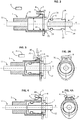
- FIGS 2, 3, 3A, 4 and 4A illustrate a first embodiment of the fluid connection, which comprises a female plug 1, and a male plug 2, intended to be inserted into the female plug as far as a final coupling position shown in the figure 3 , according to a coupling / decoupling movement parallel to the axial direction X.
- the female plug 1 comprises an internal cylindrical receiving portion 14, of circular section and of diameter D, which is slightly greater than the outside diameter of the male plug intended to be inserted into the female plug.
- an O-ring 6 positioned in a groove in the male plug serves as a sealing means between the male plug and the female plug when these are in the coupling position as shown in figures 3 and 4 .
- a locking device is provided.
- movable primary 3 which is presented as a plate 7 arranged transversely to the axis X, with an operating portion 8 arranged perpendicular to said plate.
- the plate 7 comprises a central orifice 70 substantially circular and of diameter slightly greater than the diameter of the male plug; in the example illustrated here, the primary locking device 3 forms a separate part from the female plug 1 proper, which makes it possible to choose different plastic materials according to the various compatibility constraints with the fluids transported and the requirements of elasticity for the deformation of the parts.
- the primary locking device 3, also called the primary lock 3 can be moved between a locking position 30 and an unlocking position 31 shown in dotted lines on the figure 3 .
- the axial orifice 70 of the primary lock 3 is of diameter slightly greater than the diameter of the male plug, and in its lower part, there is provided at least one projection 33 or an edge 33 of the orifice intended to be housed in a 24 annular groove of the male plug.
- This projection or border 33 also comes to bear on a shoulder 23 formed in the male plug 2, which ensures the anti-withdrawal locking function.
- the conical part 26 thereof pushes the projection 33 downwards so that the axial orifice 70 of the primary lock 3 is in a position substantially coaxial with the X axis and allows the progression of the insertion movement to the final coupling position.
- it is the entire primary lock which moves downwards, then rises to its locked position when the male and female plugs reach the final coupling position.
- the primary lock is returned to the locking position by means of an elastic return element 5 ; in the example illustrated, it is an elastic tongue 5 which can either be from the cylindrical body 10 of the female plug or from the operating portion 8 of the primary lock 3. Alternatively, this reminder could also be provided by a conventional spring.
- Unlocking the primary lock remains possible: simply press the operating portion 8 of the primary lock 3 (arrow F ) to push the primary lock towards the unlocked position, in which case the projection 33 disappears from the shoulder 23 and the male plug can be removed from the socket of the female plug.
- the male plug can advantageously move back as soon as the primary lock releases it; this provides good feedback of the unlocking for the user; the final coupling position therefore being unstable, this arrangement also makes it possible to guarantee that the primary locking is effectively engaged.
- the term 'locking position' for the primary lock 3 designates the physical position shown in the figures 2 and 4 , ie this term covers both the initial position ( Fig 2 ) without a male plug 2 being present and the locking position effective with a male plug inserted and retained in the female plug 1 ( Fig 4 ).
- a secondary lock 4 is placed in an active position, as shown in Figure 4 .
- the secondary latch 4 in the example illustrated is presented as a part in the general shape of a 'U' open in the direction of the operating portion 8, the internal recess of the U-shape being provided for housing the element. elastic return 5.
- This secondary lock is placed in an active position shown in the figure 4 , in a position where it is interposed between the cylindrical body of the female plug and the operating portion 8 of the primary lock 3.
- this secondary lock has one or more forms, in this example more precisely two forms of hooks 41 designed to cooperate each with a corresponding clip housing 81.
- Means may also be provided to prevent the primary lock from coming out of its housing; for example an elastic blade 73 arranged on the plate 7 diametrically opposite to the operating portion prevents any upward withdrawal of the primary lock beyond the locking position 30.
- the male plug is particularly simple because it is symmetrical in revolution about the axis and contains as the only deformable element O-ring.
- a collar 29 can be provided which facilitates gripping and the coupling thrust towards the female plug.
- the sheet female receives the primary lock 3 sliding transversely to the axis, we note that the primary lock is embedded on the female plug, it can move transversely between two positions but is trapped in the female plug (it can no longer be removed once it has been inserted); the female plug is also provided for receiving the secondary lock 4 which comes to interpose so as to block the movement of the primary lock.
- the primary lock is not in contact with the fluid passing through the connection; in fact, the O-ring 6 is interposed between the interior of the pipes and said primary lock.
- the secondary lock 4 can only be put in place correctly if the primary lock 3 is in its locked position (otherwise it cannot be engaged because the space is insufficient); therefore, if the coupling position has not been correctly reached, the insertion of the secondary lock will not be possible and this will give the user explicit feedback. This arrangement contributes to ensuring the quality of the connection.
- the secondary lock 4 is a separate piece which is brought in when it is necessary to permanently secure the connection.
- this secondary lock can be of a different color from the male and female plugs, so that one can see from a distance and unambiguously whether the secondary lock is in place or not.
- a lug 9 protrudes from the outer surface of the female plug, this lug is located below the operating portion 8.
- the spring 5 has a base attached to the base of said operating portion 8 and a free opposite end which carries on top of the lug 9.
- the spring and the lug have substantially the same width in the circumferential direction.
- the secondary lock 4 comprises a body 40 substantially parallelepiped from which two flexible lateral branches 42 which are arranged which are arranged to come to interface with the lug 9.
- Each of the lateral branches is provided with a hook shape 41 at its end, configured to move outward when inserting the secondary lock.
- the branches tighten and clipping is ensured.
- the sterile chain could only be broken if the connection is broken or if a specific tool is used to remove the secondary lock.
- the hooks may have ramps so that the clipping of the secondary lock is reversible, an aspect which may be advantageous in the case of a secondary lock formed by a specific piece separate from the plugs.
- FIGS. 6, 7 and 8 illustrate a second embodiment of the fluid connection, which comprises a female plug 1, and a male plug 2, as before.
- the male and female plugs are shown cut in a diametrical plane which contains the main elements of coupling and locking; over the major part of the circumference of the parts, these can be generally symmetrical of revolution around the X axis , except at the location of the main locking elements.
- the general shape of the male female plugs can be similar to the products of the SBL series from the supplier 'Value Plastics', that is to say present a general section in ellipse shape, with a larger radial dimension at the location clips and a smaller radial dimension elsewhere.
- the male plug 2 comprises a cylindrical central portion 13 of revolution configured on the one hand to be received in the female plug and on the other hand to receive a tube 12 or pipe forming the second pipe.
- the male plug includes two elastic clips 3 diametrically opposite which form the primary locking device of the connection.
- the branches 5 carrying the locking clips are elastically deformable in a radial direction; they can flex constrained towards the axis but return in the absence of external stress to a rest position further away from the axis.
- the male plug also carries the secondary lock 4 which is in a standby position (also called “inactive”), as shown in the figures 5 and 6 , a rear reach 44 being provided to hold and guide said secondary latch in a longitudinal movement.
- the secondary lock 4 is made of relatively flexible plastic and is arranged in a substantially annular manner around the rear portion of the male plug.
- the female plug 1 comprises housings 16 extending axially and capable of receiving the aforementioned diametrical clips 3. On the rear part of each housing, there is a shoulder 17 on which will abut a projecting shape 37 of the clip. The first fluid line 11 is inserted on the rear of the female plug 1.
- the male and female plugs have reached the final coupling position, for which the protruding shape 37 is locked on the shoulder 17.
- it is still possible to decouple the connection by pressing the two diametrical clips 3 one towards the other, as illustrated in the arrows F.
- the secondary lock 4 remains in its inactive position, then the male and female plugs can be coupled and uncoupled using the primary lock.
- the secondary lock is equipped with harpoon shapes 41 which are housed in an outer groove 18 of the female plug so as to make it impossible to go back from the active position to the inactive position. A final locking of the connection is then obtained.
- FIGS 9, 10 and 11 illustrate a third embodiment of the fluid connection, which comprises a female plug 1, and a male plug 2, as before.
- the primary locking device is in the form of two diametrically opposite clips arranged on the male plug.
- the operation of the primary locking device is quite similar to what has been described for the second embodiment.
- this is arranged on the side of the female socket 1, and comprises a rear annular portion 46 which surrounds a rear tubular zone of the female plug; it also has at least two legs 47 extending axially, said legs being provided to come to be interposed respectively between the front inner portion 39 of each clip 3 and the outer cylindrical body 19 of the female plug so as to make displacement impossible clips from their locked position. The free space necessary for the unlocking movements is then occupied by the tabs 47 which prevent any unlocking movement of the clips 3.
- the rear tubular portion of the female plug comprises forms 15 (here harpoon forms) capable of cooperating with the secondary lock to retain it in the active position once it has been brought there, as illustrated in FIG. figure 11 .
- forms 15 here harpoon forms
- the shapes 15 are exceeded and play a blocking role to prevent any movement of the secondary lock to the right.
- the radial size can be reduced, but the axial grip is a little larger; in the second mode, conversely, the axial dimension of the secure connection is optimized, with a slightly larger radial dimension.
- a variant is provided, the aim of which is to prevent bringing the secondary lock 4 into its active position as long as the connection is not in the final coupling position and as long as the primary lock is not in its locking position.
- deformable lances 91 which in their rest position prevent the movement of the secondary latch towards its active position (cf. Fig 12 ).
- Each of these deformable lances 91 is intended to be moved by an elastic loop 92 arranged opposite the head portion of the clip 3.
- the elastic handle 92 When the male plug is inserted into the female plug, the elastic handle 92 first bears on the chamfer 93 of the front edge of the female plug and then presses the deformable lance 91 in the radial direction inwards; therefore, it then disappears inward and allows the secondary lock 4 to move to the left (cf. Fig 13 ).
- the secondary lock 4 can leave its inactive position only on condition that the final coupling position is reached and that the primary lock is in the locked position.
- the diameter of the fluid pipe is typically between 1 and 15 mm.
- the radial dimensions of the male and female plugs can be between 10 mm and 30 mm.
- the parts described are made of plastic; some of them can be transparent so that one can visually check what is happening in the fluid pipeline; moreover the secondary lock can be of a particularly conspicuous color so that its presence can be easily verified (cf. Fig. 5C ).
Landscapes
- Engineering & Computer Science (AREA)
- General Engineering & Computer Science (AREA)
- Health & Medical Sciences (AREA)
- Mechanical Engineering (AREA)
- Heart & Thoracic Surgery (AREA)
- Hematology (AREA)
- Anesthesiology (AREA)
- Biomedical Technology (AREA)
- Pulmonology (AREA)
- Life Sciences & Earth Sciences (AREA)
- Animal Behavior & Ethology (AREA)
- General Health & Medical Sciences (AREA)
- Public Health (AREA)
- Veterinary Medicine (AREA)
- Quick-Acting Or Multi-Walled Pipe Joints (AREA)
- Infusion, Injection, And Reservoir Apparatuses (AREA)
Claims (7)
- Fluidverbindungsvorrichtung (10) zum Anschließen einer ersten Fluidleitung (11) an eine zweite Fluidleitung (12), wobei die Vorrichtung aufweist:- eine aus einem Kunststoffmaterial hergestellte Steckbuchse (1), die mit der ersten Fluidleitung verbunden ist,- einen aus einem Kunststoffmaterial hergestellten Stecker (2), der mit der zweiten Fluidleitung verbunden ist und konfiguriert ist, gemäß einer zu einer axialen Richtung (X) parallelen Kopplung/Entkopplung-Bewegung in die Steckbuchse bis zu einer Kopplungsendposition eingeführt zu werden,- eine zwischen zwei Positionen transversal verschiebbare primäre Verriegelungsvorrichtung (3), die an der Steckbuchse angeordnet ist und ein zu der Steckbuchse separates und zu dem Stecker separates Stück bildet und eine Verriegelungsposition (30) hat, in der sie verhindert, dass der Stecker und die Steckbuchse die Kopplungsendposition verlassen, wobei die primäre Verriegelungsvorrichtung (3) auf eine transversal zur axialen Richtung (X) gleitende Weise an der Steckbuchse (1) gebordet und darin gefangen ist, wobei sich die primäre Verriegelungsvorrichtung (3) als eine transversal bezüglich der axialen Richtung (X) angeordnete Platte (7) präsentiert, mit einem senkrecht zu der Platte angeordneten Betätigungsabschnitt (8), wobei die Platte (7) eine im Wesentlichen kreisförmige axiale zentrale Öffnung (70) aufweist, deren Durchmesser geringfügig größer als der Durchmesser des Steckers (2) ist, wobei mindestens ein Vorsprung (33) oder eine Leiste (33) in einem unteren Teil der Öffnung (70) vorgesehen ist und dazu bestimmt ist, in einer ringförmigen Auskehlung des Steckers aufgenommen zu werden, wobei der Vorsprung (33) oder die Leiste (33) an einer in dem Stecker (2) ausgesparten Schulter (23) zum Anschlag kommt, was erlaubt, eine gegen Zurückziehen gesicherte Verriegelungsfunktion zu gewährleisten,- einen verschiebbaren sekundären Riegel (4), der eine geeignete aktive Position hat, um das Betätigen der primären Verriegelungsvorrichtung (3) aus ihrer Verriegelungsposition zu verhindern, wobei der sekundäre Riegel ein separates Stück ist, das in seiner aktiven Position in Eingriff kommen kann, um die Verschiebung der primären Verriegelungsvorrichtung zu blockieren, wobei der sekundäre Riegel konfiguriert ist, auf eine nichtreversible Weise in seiner aktiven Position eingerastet zu werden, wodurch die Fluidverbindungsvorrichtung einen endgültigen und nichtlösbaren Zusammenschluss der ersten und zweiten Leitung herstellt, um so zu garantieren, dass die Sterilitätskette gut gewahrt bleibt,in welcher der sekundäre Riegel (4) nur dann in die aktive Position gebracht werden kann, wenn die primäre Verriegelungsvorrichtung (3) in ihrer Verriegelungsposition ist, wobei der sekundäre Riegel (4) verhindert, dass sich die primäre Verriegelungsvorrichtung (3) aus ihrer Verriegelungsposition entfernt,
dadurch gekennzeichnet, dass der sekundäre Riegel (4) ein Stück ist, das separat zu der Steckbuchse und dem Stecker (1, 2) geliefert und bereitgestellt werden kann, so dass die Steckbuchse (1) und der Stecker (2) in Anwesenheit der in der Steckbuchse (1) gefangenen primären Verriegelungsvorrichtung (3) und in Abwesenheit des sekundären Riegels (4) in ihre Kopplungsendposition zusammengefügt werden können, und dadurch, dass die Steckbuchse (1) vorgesehen ist, selektiv nach Erreichen der Kopplungsendposition und nach Erreichen der Verriegelungsposition (30) den sekundären Riegel (4) zu empfangen. - Vorrichtung nach Anspruch 1, in welcher die primäre Verriegelungsvorrichtung (3) einen Betätigungsabschnitt (8) aufweist, um die primäre Verriegelungsvorrichtung hin zu einer Entriegelungsposition zu stoßen, in welchem Fall der Vorsprung (33) sich von der Schulter (23) löst und der Stecker (2) sich gemäß einer Entkopplungsbewegung, die zur axialen Richtung (X) parallel ist, verschiebt, und in welcher der sekundäre Riegel (4) den Zugriff auf das Betätigen der primären Verriegelungsvorrichtung (3) verhindert, wenn der sekundäre Riegel (4) in der aktiven Position ist, in der er zwischen einem zylindrischen Körper der Steckbuchse (1) und dem Betätigungsabschnitt (8) der primären Verriegelungsvorrichtung (3) angeordnet ist, die senkrecht zu der Platte (7) ist.
- Vorrichtung nach einem der Ansprüche 1 bis 2, in welcher die primäre Verriegelungsvorrichtung (3) mit Hilfe einer elastischen Rückstelleinrichtung (5) in ihre Verriegelungsposition (30) zurückgestellt wird.
- Vorrichtung nach einem der Ansprüche 1 bis 3, in welcher die radiale Abmessung sowohl der Steckbuchse (1) als auch des Steckers (2) zwischen 10mm und 30mm ist.
- Verwendung der Fluidverbindungsvorrichtung (10) nach einem der Ansprüche 1 bis 4, in welcher die Fluidverbindungsvorrichtung dazu dient, zwei Leitungen für ein auf dem medizinischen Gebiet verwendbares flüssiges Fluid zusammenzuschließen.
- Verwendung der Fluidverbindungsvorrichtung (10) nach einem der Ansprüche 1 bis 4, in welcher die Fluidverbindungsvorrichtung dazu dient, zwei Leitungen für ein auf dem medizinischen Gebiet verwendbares gasförmiges Fluid zusammenzuschließen.
- Verwendung der Fluidverbindungsvorrichtung (10) nach einem der Ansprüche 1 bis 4, in welcher die Fluidverbindungsvorrichtung dazu dient, zwei Leitungen für ein auf dem medizinischen Gebiet verwendbares pastenartiges Fluid zusammenzuschließen.
Applications Claiming Priority (2)
| Application Number | Priority Date | Filing Date | Title |
|---|---|---|---|
| FR1353382A FR3004506B1 (fr) | 2013-04-15 | 2013-04-15 | Connexion fluidique securisee. |
| PCT/FR2014/050865 WO2014170584A1 (fr) | 2013-04-15 | 2014-04-10 | Connexion fluidique sécurisée |
Publications (2)
| Publication Number | Publication Date |
|---|---|
| EP2986879A1 EP2986879A1 (de) | 2016-02-24 |
| EP2986879B1 true EP2986879B1 (de) | 2020-03-04 |
Family
ID=48745982
Family Applications (1)
| Application Number | Title | Priority Date | Filing Date |
|---|---|---|---|
| EP14723461.1A Active EP2986879B1 (de) | 2013-04-15 | 2014-04-10 | Sichere flüssigkeitsverbindung |
Country Status (5)
| Country | Link |
|---|---|
| US (1) | US10557580B2 (de) |
| EP (1) | EP2986879B1 (de) |
| CN (1) | CN105143747B (de) |
| FR (1) | FR3004506B1 (de) |
| WO (1) | WO2014170584A1 (de) |
Families Citing this family (32)
| Publication number | Priority date | Publication date | Assignee | Title |
|---|---|---|---|---|
| JP6499178B2 (ja) | 2013-08-29 | 2019-04-10 | サノフイSanofi | 薬剤容器用の安全デバイス |
| FR3017688B1 (fr) * | 2014-02-14 | 2016-11-25 | Sartorius Stedim Fmt Sas | Ensemble de raccordement fluidique modulaire. |
| DE102014113151A1 (de) * | 2014-09-12 | 2016-05-12 | Eugen Forschner Gmbh | Verriegelungselement für einen Konnektor |
| DE102016101911A1 (de) * | 2016-02-03 | 2017-08-03 | B. Braun Avitum Ag | Medizinische Kupplung und medizinisches System mit einer medizinischen Kupplung |
| JP6834204B2 (ja) * | 2016-07-11 | 2021-02-24 | 株式会社ジェイ・エム・エス | オスコネクタ |
| CN106523825A (zh) * | 2016-12-30 | 2017-03-22 | 广东美的制冷设备有限公司 | 接头组件和具有其的除湿机 |
| GB201710279D0 (en) * | 2017-06-28 | 2017-08-09 | Ge Healthcare Bio Sciences Ab | Improvements in and relating to bioprocessing equipment and fluid couplings therefor |
| CN109695136B (zh) * | 2017-10-23 | 2022-08-30 | 青岛海尔洗涤电器有限公司 | 衣物处理装置 |
| MX2021006325A (es) * | 2018-11-30 | 2021-08-11 | Becton Dickinson Co | Tapon conector universal activado giratoriamente. |
| US11353117B1 (en) | 2020-01-17 | 2022-06-07 | Vulcan Industrial Holdings, LLC | Valve seat insert system and method |
| WO2021252197A1 (en) | 2020-06-12 | 2021-12-16 | Colder Products Company | Fluid couplings |
| US12049889B2 (en) | 2020-06-30 | 2024-07-30 | Vulcan Industrial Holdings, LLC | Packing bore wear sleeve retainer system |
| US11421679B1 (en) | 2020-06-30 | 2022-08-23 | Vulcan Industrial Holdings, LLC | Packing assembly with threaded sleeve for interaction with an installation tool |
| US11421680B1 (en) | 2020-06-30 | 2022-08-23 | Vulcan Industrial Holdings, LLC | Packing bore wear sleeve retainer system |
| US11384756B1 (en) | 2020-08-19 | 2022-07-12 | Vulcan Industrial Holdings, LLC | Composite valve seat system and method |
| USD997992S1 (en) | 2020-08-21 | 2023-09-05 | Vulcan Industrial Holdings, LLC | Fluid end for a pumping system |
| USD980876S1 (en) | 2020-08-21 | 2023-03-14 | Vulcan Industrial Holdings, LLC | Fluid end for a pumping system |
| USD986928S1 (en) | 2020-08-21 | 2023-05-23 | Vulcan Industrial Holdings, LLC | Fluid end for a pumping system |
| US12366245B1 (en) | 2020-08-27 | 2025-07-22 | Vulcan Industrial Holdings, LLC | Connecting rod assembly for reciprocating pump |
| US11391374B1 (en) | 2021-01-14 | 2022-07-19 | Vulcan Industrial Holdings, LLC | Dual ring stuffing box |
| US12055221B2 (en) | 2021-01-14 | 2024-08-06 | Vulcan Industrial Holdings, LLC | Dual ring stuffing box |
| US12292120B1 (en) | 2021-02-23 | 2025-05-06 | Vulcan Industrial Holdings, LLC | System and method for valve assembly |
| US12510164B1 (en) | 2021-08-18 | 2025-12-30 | Vulcan Industrial Holdings, LLC | Sleeved fluid end |
| US11846356B1 (en) | 2021-08-18 | 2023-12-19 | Vulcan Industrial Holdings, LLC | Self-locking plug |
| WO2023132965A1 (en) * | 2022-01-06 | 2023-07-13 | Entegris, Inc. | Aseptic coupling assembly and method of aseptic coupling |
| US12140240B1 (en) | 2022-01-19 | 2024-11-12 | Vulcan Industrial Holdings, LLC | Gradient material structures and methods of forming the same |
| US12297922B1 (en) | 2022-03-04 | 2025-05-13 | Vulcan Industrial Holdings, LLC | Valve seat with embedded structure and related methods |
| US11434900B1 (en) | 2022-04-25 | 2022-09-06 | Vulcan Industrial Holdings, LLC | Spring controlling valve |
| US11920684B1 (en) | 2022-05-17 | 2024-03-05 | Vulcan Industrial Holdings, LLC | Mechanically or hybrid mounted valve seat |
| USD1113987S1 (en) | 2022-05-20 | 2026-02-17 | Vulcan Industrial Holdings, LLC | Header ring for a pumping system |
| USD1061623S1 (en) | 2022-08-03 | 2025-02-11 | Vulcan Industrial Holdings, LLC | Fluid end for a pumping system |
| US12292121B2 (en) | 2023-08-10 | 2025-05-06 | Vulcan Industrial Holdings, LLC | Valve member including cavity, and related assemblies, systems, and methods |
Citations (3)
| Publication number | Priority date | Publication date | Assignee | Title |
|---|---|---|---|---|
| FR1487324A (fr) * | 1966-01-04 | 1967-07-07 | Staubli Freres & Cie | Dispositif de raccord rapide pour la jonction de canalisations et analogues |
| US20100019487A1 (en) * | 2008-07-25 | 2010-01-28 | Decler Charles Peter | Coupling with Low Friction Material |
| EP2224158A1 (de) * | 2007-12-19 | 2010-09-01 | Nifco Inc. | Bestätigungsmechanismus für abgeschlossene kopplung |
Family Cites Families (11)
| Publication number | Priority date | Publication date | Assignee | Title |
|---|---|---|---|---|
| DE3710853A1 (de) * | 1987-04-01 | 1988-10-20 | Bayerische Motoren Werke Ag | Steckverbindung fuer ein rohr oder dergleichen in einem aufnahmeteil |
| WO1990010814A1 (en) | 1989-03-13 | 1990-09-20 | Colder Products Company | Two piece molded female coupling |
| US5395140A (en) * | 1993-05-13 | 1995-03-07 | Enhanced Applications, L.C. | Secondary latch and indicator for fluid coupling |
| US5401063A (en) * | 1993-07-19 | 1995-03-28 | Enhanced Applications, L.C. | Primary/secondary retainer for beaded/flared tubing |
| FR2808862B1 (fr) * | 2000-05-10 | 2002-07-19 | Legris Sa | Dispositif de raccordement d'un embout a un organe |
| DE102004053538A1 (de) * | 2004-11-05 | 2006-05-11 | Veritas Ag | Kupplungsvorrichtung zum Verbinden von Leitungen und Kraftfahrzeug mit einer derartigen Kupplungsvorrichtung |
| JP2006292166A (ja) * | 2005-03-16 | 2006-10-26 | Tokai Rubber Ind Ltd | コネクタ装置及びチェッカー |
| DE202005015966U1 (de) * | 2005-10-10 | 2007-02-15 | Voss Automotive Gmbh | Steckverbinder für Medienleitungen |
| DE102009033943A1 (de) * | 2009-07-14 | 2011-01-20 | Aft Inh. Dirk Kramer E.K. | Steckkupplung |
| FR2972783B1 (fr) * | 2011-03-15 | 2013-03-22 | Hutchinson | Dispositif de raccordement pour transfert de fluide, circuit l'incorporant et son procede de montage/demontage. |
| US8366154B2 (en) * | 2011-06-15 | 2013-02-05 | Wang Cheng-An | Water pipe connector |
-
2013
- 2013-04-15 FR FR1353382A patent/FR3004506B1/fr not_active Expired - Fee Related
-
2014
- 2014-04-10 US US14/784,609 patent/US10557580B2/en active Active
- 2014-04-10 CN CN201480021112.3A patent/CN105143747B/zh active Active
- 2014-04-10 EP EP14723461.1A patent/EP2986879B1/de active Active
- 2014-04-10 WO PCT/FR2014/050865 patent/WO2014170584A1/fr not_active Ceased
Patent Citations (3)
| Publication number | Priority date | Publication date | Assignee | Title |
|---|---|---|---|---|
| FR1487324A (fr) * | 1966-01-04 | 1967-07-07 | Staubli Freres & Cie | Dispositif de raccord rapide pour la jonction de canalisations et analogues |
| EP2224158A1 (de) * | 2007-12-19 | 2010-09-01 | Nifco Inc. | Bestätigungsmechanismus für abgeschlossene kopplung |
| US20100019487A1 (en) * | 2008-07-25 | 2010-01-28 | Decler Charles Peter | Coupling with Low Friction Material |
Also Published As
| Publication number | Publication date |
|---|---|
| US20160076679A1 (en) | 2016-03-17 |
| FR3004506B1 (fr) | 2015-11-06 |
| US10557580B2 (en) | 2020-02-11 |
| CN105143747A (zh) | 2015-12-09 |
| CN105143747B (zh) | 2017-12-08 |
| EP2986879A1 (de) | 2016-02-24 |
| WO2014170584A1 (fr) | 2014-10-23 |
| FR3004506A1 (fr) | 2014-10-17 |
Similar Documents
| Publication | Publication Date | Title |
|---|---|---|
| EP2986879A1 (de) | Sichere flüssigkeitsverbindung | |
| EP3014161B1 (de) | Verriegelnder fluidverbinder | |
| EP2536463B1 (de) | Set aus einfach zu reinigenden steckverbindern für einen flüssigkeitskreislauf | |
| EP2736582B1 (de) | Tropffreie direktflussverbinder mit sicherer arretierung | |
| EP1219885B1 (de) | Steckdosenelement und Schnellkupplung und Vorrichtung die ein solches Element enthält | |
| EP1752697B1 (de) | Kupplungsanordnung für einen Flüssigkeitskreislauf | |
| FR2931363A1 (fr) | Connecteur pour circuit de liquide, notamment a usage medical et utilisation d'un tel connecteur | |
| EP2878873B1 (de) | Patronenartige schnellkupplungsvorrichtung | |
| EP1281018B1 (de) | Vorrichtung zum anschluss eines stutzens an ein element | |
| EP2878872B1 (de) | Schnellanschluss zur lösbaren Verbindung von zwei Rohren | |
| FR3070038A1 (fr) | Dispositif de conditionnement d'objet, ensemble et procede d'extraction correspondant | |
| FR3017688A1 (fr) | Ensemble de raccordement fluidique modulaire. | |
| EP1463674A1 (de) | Fluidproduktabgabeventil und dieses umfassende fluidproduktabgabevorrichtung | |
| FR2952813A1 (fr) | Dispositif de liaison entre deux contenants, destine notamment a un usage medical | |
| EP2282805A1 (de) | Verbessertes verbindungsglied zur medizinischen anwendung | |
| EP3855058B1 (de) | Rohrverbindungsvorrichtung | |
| WO2010055222A1 (fr) | Dispositif de raccordement ayant des zones inversees d'etancheite et d'accrochage | |
| WO2025209787A1 (fr) | Dispositif de raccordement aseptique d' un tube comprenant une membrane de protection | |
| WO2016034779A1 (fr) | Systeme de maintien d'un adaptateur sur un cone d'extremite d'une seringue, et ensemble comprenant un tel systeme de maintien | |
| FR3008159A1 (fr) | Dispositif de raccordement a zones externes reduites de retention de poussiere | |
| EP3726116A1 (de) | Verbindungsvorrichtung mit berührungsempfindlicher und optischer anzeige | |
| FR2800435A1 (fr) | Dispositif de raccordement de conduites destinees au transport d'un fluide | |
| EP3638532A1 (de) | Vorrichtung zum übersteuern einer vorrichtung zur verhinderung von fehlbetankung | |
| FR2935358A1 (fr) | Recipient et appareil de combustion pourvu d'un tel recipient. |
Legal Events
| Date | Code | Title | Description |
|---|---|---|---|
| PUAI | Public reference made under article 153(3) epc to a published international application that has entered the european phase |
Free format text: ORIGINAL CODE: 0009012 |
|
| 17P | Request for examination filed |
Effective date: 20150917 |
|
| AK | Designated contracting states |
Kind code of ref document: A1 Designated state(s): AL AT BE BG CH CY CZ DE DK EE ES FI FR GB GR HR HU IE IS IT LI LT LU LV MC MK MT NL NO PL PT RO RS SE SI SK SM TR |
|
| AX | Request for extension of the european patent |
Extension state: BA ME |
|
| DAX | Request for extension of the european patent (deleted) | ||
| STAA | Information on the status of an ep patent application or granted ep patent |
Free format text: STATUS: EXAMINATION IS IN PROGRESS |
|
| 17Q | First examination report despatched |
Effective date: 20161212 |
|
| GRAP | Despatch of communication of intention to grant a patent |
Free format text: ORIGINAL CODE: EPIDOSNIGR1 |
|
| STAA | Information on the status of an ep patent application or granted ep patent |
Free format text: STATUS: GRANT OF PATENT IS INTENDED |
|
| INTG | Intention to grant announced |
Effective date: 20191031 |
|
| GRAS | Grant fee paid |
Free format text: ORIGINAL CODE: EPIDOSNIGR3 |
|
| GRAA | (expected) grant |
Free format text: ORIGINAL CODE: 0009210 |
|
| STAA | Information on the status of an ep patent application or granted ep patent |
Free format text: STATUS: THE PATENT HAS BEEN GRANTED |
|
| AK | Designated contracting states |
Kind code of ref document: B1 Designated state(s): AL AT BE BG CH CY CZ DE DK EE ES FI FR GB GR HR HU IE IS IT LI LT LU LV MC MK MT NL NO PL PT RO RS SE SI SK SM TR |
|
| REG | Reference to a national code |
Ref country code: GB Ref legal event code: FG4D Free format text: NOT ENGLISH |
|
| REG | Reference to a national code |
Ref country code: CH Ref legal event code: EP |
|
| REG | Reference to a national code |
Ref country code: AT Ref legal event code: REF Ref document number: 1240775 Country of ref document: AT Kind code of ref document: T Effective date: 20200315 |
|
| REG | Reference to a national code |
Ref country code: DE Ref legal event code: R096 Ref document number: 602014061831 Country of ref document: DE |
|
| REG | Reference to a national code |
Ref country code: IE Ref legal event code: FG4D Free format text: LANGUAGE OF EP DOCUMENT: FRENCH |
|
| PG25 | Lapsed in a contracting state [announced via postgrant information from national office to epo] |
Ref country code: NO Free format text: LAPSE BECAUSE OF FAILURE TO SUBMIT A TRANSLATION OF THE DESCRIPTION OR TO PAY THE FEE WITHIN THE PRESCRIBED TIME-LIMIT Effective date: 20200604 Ref country code: FI Free format text: LAPSE BECAUSE OF FAILURE TO SUBMIT A TRANSLATION OF THE DESCRIPTION OR TO PAY THE FEE WITHIN THE PRESCRIBED TIME-LIMIT Effective date: 20200304 Ref country code: RS Free format text: LAPSE BECAUSE OF FAILURE TO SUBMIT A TRANSLATION OF THE DESCRIPTION OR TO PAY THE FEE WITHIN THE PRESCRIBED TIME-LIMIT Effective date: 20200304 |
|
| REG | Reference to a national code |
Ref country code: NL Ref legal event code: MP Effective date: 20200304 |
|
| PG25 | Lapsed in a contracting state [announced via postgrant information from national office to epo] |
Ref country code: GR Free format text: LAPSE BECAUSE OF FAILURE TO SUBMIT A TRANSLATION OF THE DESCRIPTION OR TO PAY THE FEE WITHIN THE PRESCRIBED TIME-LIMIT Effective date: 20200605 Ref country code: BG Free format text: LAPSE BECAUSE OF FAILURE TO SUBMIT A TRANSLATION OF THE DESCRIPTION OR TO PAY THE FEE WITHIN THE PRESCRIBED TIME-LIMIT Effective date: 20200604 Ref country code: LV Free format text: LAPSE BECAUSE OF FAILURE TO SUBMIT A TRANSLATION OF THE DESCRIPTION OR TO PAY THE FEE WITHIN THE PRESCRIBED TIME-LIMIT Effective date: 20200304 Ref country code: SE Free format text: LAPSE BECAUSE OF FAILURE TO SUBMIT A TRANSLATION OF THE DESCRIPTION OR TO PAY THE FEE WITHIN THE PRESCRIBED TIME-LIMIT Effective date: 20200304 Ref country code: HR Free format text: LAPSE BECAUSE OF FAILURE TO SUBMIT A TRANSLATION OF THE DESCRIPTION OR TO PAY THE FEE WITHIN THE PRESCRIBED TIME-LIMIT Effective date: 20200304 |
|
| REG | Reference to a national code |
Ref country code: LT Ref legal event code: MG4D |
|
| PG25 | Lapsed in a contracting state [announced via postgrant information from national office to epo] |
Ref country code: NL Free format text: LAPSE BECAUSE OF FAILURE TO SUBMIT A TRANSLATION OF THE DESCRIPTION OR TO PAY THE FEE WITHIN THE PRESCRIBED TIME-LIMIT Effective date: 20200304 |
|
| PG25 | Lapsed in a contracting state [announced via postgrant information from national office to epo] |
Ref country code: ES Free format text: LAPSE BECAUSE OF FAILURE TO SUBMIT A TRANSLATION OF THE DESCRIPTION OR TO PAY THE FEE WITHIN THE PRESCRIBED TIME-LIMIT Effective date: 20200304 Ref country code: PT Free format text: LAPSE BECAUSE OF FAILURE TO SUBMIT A TRANSLATION OF THE DESCRIPTION OR TO PAY THE FEE WITHIN THE PRESCRIBED TIME-LIMIT Effective date: 20200729 Ref country code: SK Free format text: LAPSE BECAUSE OF FAILURE TO SUBMIT A TRANSLATION OF THE DESCRIPTION OR TO PAY THE FEE WITHIN THE PRESCRIBED TIME-LIMIT Effective date: 20200304 Ref country code: IS Free format text: LAPSE BECAUSE OF FAILURE TO SUBMIT A TRANSLATION OF THE DESCRIPTION OR TO PAY THE FEE WITHIN THE PRESCRIBED TIME-LIMIT Effective date: 20200704 Ref country code: SM Free format text: LAPSE BECAUSE OF FAILURE TO SUBMIT A TRANSLATION OF THE DESCRIPTION OR TO PAY THE FEE WITHIN THE PRESCRIBED TIME-LIMIT Effective date: 20200304 Ref country code: CZ Free format text: LAPSE BECAUSE OF FAILURE TO SUBMIT A TRANSLATION OF THE DESCRIPTION OR TO PAY THE FEE WITHIN THE PRESCRIBED TIME-LIMIT Effective date: 20200304 Ref country code: LT Free format text: LAPSE BECAUSE OF FAILURE TO SUBMIT A TRANSLATION OF THE DESCRIPTION OR TO PAY THE FEE WITHIN THE PRESCRIBED TIME-LIMIT Effective date: 20200304 Ref country code: EE Free format text: LAPSE BECAUSE OF FAILURE TO SUBMIT A TRANSLATION OF THE DESCRIPTION OR TO PAY THE FEE WITHIN THE PRESCRIBED TIME-LIMIT Effective date: 20200304 Ref country code: RO Free format text: LAPSE BECAUSE OF FAILURE TO SUBMIT A TRANSLATION OF THE DESCRIPTION OR TO PAY THE FEE WITHIN THE PRESCRIBED TIME-LIMIT Effective date: 20200304 |
|
| REG | Reference to a national code |
Ref country code: AT Ref legal event code: MK05 Ref document number: 1240775 Country of ref document: AT Kind code of ref document: T Effective date: 20200304 |
|
| REG | Reference to a national code |
Ref country code: DE Ref legal event code: R097 Ref document number: 602014061831 Country of ref document: DE |
|
| PG25 | Lapsed in a contracting state [announced via postgrant information from national office to epo] |
Ref country code: MC Free format text: LAPSE BECAUSE OF FAILURE TO SUBMIT A TRANSLATION OF THE DESCRIPTION OR TO PAY THE FEE WITHIN THE PRESCRIBED TIME-LIMIT Effective date: 20200304 |
|
| PLBE | No opposition filed within time limit |
Free format text: ORIGINAL CODE: 0009261 |
|
| STAA | Information on the status of an ep patent application or granted ep patent |
Free format text: STATUS: NO OPPOSITION FILED WITHIN TIME LIMIT |
|
| PG25 | Lapsed in a contracting state [announced via postgrant information from national office to epo] |
Ref country code: LU Free format text: LAPSE BECAUSE OF NON-PAYMENT OF DUE FEES Effective date: 20200410 Ref country code: DK Free format text: LAPSE BECAUSE OF FAILURE TO SUBMIT A TRANSLATION OF THE DESCRIPTION OR TO PAY THE FEE WITHIN THE PRESCRIBED TIME-LIMIT Effective date: 20200304 Ref country code: AT Free format text: LAPSE BECAUSE OF FAILURE TO SUBMIT A TRANSLATION OF THE DESCRIPTION OR TO PAY THE FEE WITHIN THE PRESCRIBED TIME-LIMIT Effective date: 20200304 |
|
| REG | Reference to a national code |
Ref country code: BE Ref legal event code: MM Effective date: 20200430 |
|
| 26N | No opposition filed |
Effective date: 20201207 |
|
| PG25 | Lapsed in a contracting state [announced via postgrant information from national office to epo] |
Ref country code: PL Free format text: LAPSE BECAUSE OF FAILURE TO SUBMIT A TRANSLATION OF THE DESCRIPTION OR TO PAY THE FEE WITHIN THE PRESCRIBED TIME-LIMIT Effective date: 20200304 Ref country code: BE Free format text: LAPSE BECAUSE OF NON-PAYMENT OF DUE FEES Effective date: 20200430 Ref country code: SI Free format text: LAPSE BECAUSE OF FAILURE TO SUBMIT A TRANSLATION OF THE DESCRIPTION OR TO PAY THE FEE WITHIN THE PRESCRIBED TIME-LIMIT Effective date: 20200304 |
|
| PG25 | Lapsed in a contracting state [announced via postgrant information from national office to epo] |
Ref country code: IE Free format text: LAPSE BECAUSE OF NON-PAYMENT OF DUE FEES Effective date: 20200410 |
|
| PG25 | Lapsed in a contracting state [announced via postgrant information from national office to epo] |
Ref country code: TR Free format text: LAPSE BECAUSE OF FAILURE TO SUBMIT A TRANSLATION OF THE DESCRIPTION OR TO PAY THE FEE WITHIN THE PRESCRIBED TIME-LIMIT Effective date: 20200304 Ref country code: MT Free format text: LAPSE BECAUSE OF FAILURE TO SUBMIT A TRANSLATION OF THE DESCRIPTION OR TO PAY THE FEE WITHIN THE PRESCRIBED TIME-LIMIT Effective date: 20200304 Ref country code: CY Free format text: LAPSE BECAUSE OF FAILURE TO SUBMIT A TRANSLATION OF THE DESCRIPTION OR TO PAY THE FEE WITHIN THE PRESCRIBED TIME-LIMIT Effective date: 20200304 |
|
| PG25 | Lapsed in a contracting state [announced via postgrant information from national office to epo] |
Ref country code: MK Free format text: LAPSE BECAUSE OF FAILURE TO SUBMIT A TRANSLATION OF THE DESCRIPTION OR TO PAY THE FEE WITHIN THE PRESCRIBED TIME-LIMIT Effective date: 20200304 Ref country code: AL Free format text: LAPSE BECAUSE OF FAILURE TO SUBMIT A TRANSLATION OF THE DESCRIPTION OR TO PAY THE FEE WITHIN THE PRESCRIBED TIME-LIMIT Effective date: 20200304 |
|
| P01 | Opt-out of the competence of the unified patent court (upc) registered |
Effective date: 20230517 |
|
| REG | Reference to a national code |
Ref country code: DE Ref legal event code: R081 Ref document number: 602014061831 Country of ref document: DE Owner name: SARTORIUS STEDIM FMT, FR Free format text: FORMER OWNER: SARTORIUS STEDIM FMT SAS, AUBAGNE, FR Ref country code: DE Ref legal event code: R081 Ref document number: 602014061831 Country of ref document: DE Owner name: SARTORIUS STEDIM, FR Free format text: FORMER OWNER: SARTORIUS STEDIM FMT SAS, AUBAGNE, FR |
|
| REG | Reference to a national code |
Ref country code: DE Ref legal event code: R081 Ref document number: 602014061831 Country of ref document: DE Owner name: SARTORIUS STEDIM FMT, FR Free format text: FORMER OWNER: SARTORIUS STEDIM, AUBAGNE, FR |
|
| PGFP | Annual fee paid to national office [announced via postgrant information from national office to epo] |
Ref country code: DE Payment date: 20250417 Year of fee payment: 12 |
|
| PGFP | Annual fee paid to national office [announced via postgrant information from national office to epo] |
Ref country code: IT Payment date: 20250430 Year of fee payment: 12 |
|
| PGFP | Annual fee paid to national office [announced via postgrant information from national office to epo] |
Ref country code: FR Payment date: 20250422 Year of fee payment: 12 |
|
| PGFP | Annual fee paid to national office [announced via postgrant information from national office to epo] |
Ref country code: CH Payment date: 20250501 Year of fee payment: 12 |
|
| PGFP | Annual fee paid to national office [announced via postgrant information from national office to epo] |
Ref country code: GB Payment date: 20260324 Year of fee payment: 13 |
|
| REG | Reference to a national code |
Ref country code: CH Ref legal event code: U11 Free format text: ST27 STATUS EVENT CODE: U-0-0-U10-U11 (AS PROVIDED BY THE NATIONAL OFFICE) Effective date: 20260501 |