EP2987513B1 - Dispositif d'assistance au chauffage doté d'une coque auto-expansible - Google Patents
Dispositif d'assistance au chauffage doté d'une coque auto-expansible Download PDFInfo
- Publication number
- EP2987513B1 EP2987513B1 EP15184605.2A EP15184605A EP2987513B1 EP 2987513 B1 EP2987513 B1 EP 2987513B1 EP 15184605 A EP15184605 A EP 15184605A EP 2987513 B1 EP2987513 B1 EP 2987513B1
- Authority
- EP
- European Patent Office
- Prior art keywords
- shell
- heart
- unit
- expandable
- electrode
- Prior art date
- Legal status (The legal status is an assumption and is not a legal conclusion. Google has not performed a legal analysis and makes no representation as to the accuracy of the status listed.)
- Active
Links
Images









Classifications
-
- A—HUMAN NECESSITIES
- A61—MEDICAL OR VETERINARY SCIENCE; HYGIENE
- A61B—DIAGNOSIS; SURGERY; IDENTIFICATION
- A61B5/00—Measuring for diagnostic purposes; Identification of persons
- A61B5/68—Arrangements of detecting, measuring or recording means, e.g. sensors, in relation to patient
- A61B5/6846—Arrangements of detecting, measuring or recording means, e.g. sensors, in relation to patient specially adapted to be brought in contact with an internal body part, i.e. invasive
- A61B5/6867—Arrangements of detecting, measuring or recording means, e.g. sensors, in relation to patient specially adapted to be brought in contact with an internal body part, i.e. invasive specially adapted to be attached or implanted in a specific body part
- A61B5/6869—Heart
-
- A—HUMAN NECESSITIES
- A61—MEDICAL OR VETERINARY SCIENCE; HYGIENE
- A61M—DEVICES FOR INTRODUCING MEDIA INTO, OR ONTO, THE BODY; DEVICES FOR TRANSDUCING BODY MEDIA OR FOR TAKING MEDIA FROM THE BODY; DEVICES FOR PRODUCING OR ENDING SLEEP OR STUPOR
- A61M60/00—Blood pumps; Devices for mechanical circulatory actuation; Balloon pumps for circulatory assistance
- A61M60/80—Constructional details other than related to driving
- A61M60/855—Constructional details other than related to driving of implantable pumps or pumping devices
- A61M60/857—Implantable blood tubes
-
- A—HUMAN NECESSITIES
- A61—MEDICAL OR VETERINARY SCIENCE; HYGIENE
- A61B—DIAGNOSIS; SURGERY; IDENTIFICATION
- A61B5/00—Measuring for diagnostic purposes; Identification of persons
- A61B5/02—Detecting, measuring or recording for evaluating the cardiovascular system, e.g. pulse, heart rate, blood pressure or blood flow
-
- A—HUMAN NECESSITIES
- A61—MEDICAL OR VETERINARY SCIENCE; HYGIENE
- A61B—DIAGNOSIS; SURGERY; IDENTIFICATION
- A61B5/00—Measuring for diagnostic purposes; Identification of persons
- A61B5/02—Detecting, measuring or recording for evaluating the cardiovascular system, e.g. pulse, heart rate, blood pressure or blood flow
- A61B5/021—Measuring pressure in heart or blood vessels
- A61B5/0215—Measuring pressure in heart or blood vessels by means inserted into the body
-
- A—HUMAN NECESSITIES
- A61—MEDICAL OR VETERINARY SCIENCE; HYGIENE
- A61B—DIAGNOSIS; SURGERY; IDENTIFICATION
- A61B5/00—Measuring for diagnostic purposes; Identification of persons
- A61B5/24—Detecting, measuring or recording bioelectric or biomagnetic signals of the body or parts thereof
- A61B5/25—Bioelectric electrodes therefor
- A61B5/279—Bioelectric electrodes therefor specially adapted for particular uses
- A61B5/28—Bioelectric electrodes therefor specially adapted for particular uses for electrocardiography [ECG]
- A61B5/283—Invasive
-
- A—HUMAN NECESSITIES
- A61—MEDICAL OR VETERINARY SCIENCE; HYGIENE
- A61M—DEVICES FOR INTRODUCING MEDIA INTO, OR ONTO, THE BODY; DEVICES FOR TRANSDUCING BODY MEDIA OR FOR TAKING MEDIA FROM THE BODY; DEVICES FOR PRODUCING OR ENDING SLEEP OR STUPOR
- A61M60/00—Blood pumps; Devices for mechanical circulatory actuation; Balloon pumps for circulatory assistance
- A61M60/10—Location thereof with respect to the patient's body
- A61M60/122—Implantable pumps or pumping devices, i.e. the blood being pumped inside the patient's body
- A61M60/126—Implantable pumps or pumping devices, i.e. the blood being pumped inside the patient's body implantable via, into, inside, in line, branching on, or around a blood vessel
- A61M60/161—Implantable pumps or pumping devices, i.e. the blood being pumped inside the patient's body implantable via, into, inside, in line, branching on, or around a blood vessel mechanically acting upon the outside of the patient's blood vessel structure, e.g. compressive structures placed around a vessel
-
- A—HUMAN NECESSITIES
- A61—MEDICAL OR VETERINARY SCIENCE; HYGIENE
- A61M—DEVICES FOR INTRODUCING MEDIA INTO, OR ONTO, THE BODY; DEVICES FOR TRANSDUCING BODY MEDIA OR FOR TAKING MEDIA FROM THE BODY; DEVICES FOR PRODUCING OR ENDING SLEEP OR STUPOR
- A61M60/00—Blood pumps; Devices for mechanical circulatory actuation; Balloon pumps for circulatory assistance
- A61M60/40—Details relating to driving
- A61M60/424—Details relating to driving for positive displacement blood pumps
- A61M60/427—Details relating to driving for positive displacement blood pumps the force acting on the blood contacting member being hydraulic or pneumatic
-
- A—HUMAN NECESSITIES
- A61—MEDICAL OR VETERINARY SCIENCE; HYGIENE
- A61M—DEVICES FOR INTRODUCING MEDIA INTO, OR ONTO, THE BODY; DEVICES FOR TRANSDUCING BODY MEDIA OR FOR TAKING MEDIA FROM THE BODY; DEVICES FOR PRODUCING OR ENDING SLEEP OR STUPOR
- A61M60/00—Blood pumps; Devices for mechanical circulatory actuation; Balloon pumps for circulatory assistance
- A61M60/50—Details relating to control
- A61M60/508—Electronic control means, e.g. for feedback regulation
- A61M60/515—Regulation using real-time patient data
- A61M60/531—Regulation using real-time patient data using blood pressure data, e.g. from blood pressure sensors
-
- A—HUMAN NECESSITIES
- A61—MEDICAL OR VETERINARY SCIENCE; HYGIENE
- A61M—DEVICES FOR INTRODUCING MEDIA INTO, OR ONTO, THE BODY; DEVICES FOR TRANSDUCING BODY MEDIA OR FOR TAKING MEDIA FROM THE BODY; DEVICES FOR PRODUCING OR ENDING SLEEP OR STUPOR
- A61M60/00—Blood pumps; Devices for mechanical circulatory actuation; Balloon pumps for circulatory assistance
- A61M60/50—Details relating to control
- A61M60/508—Electronic control means, e.g. for feedback regulation
- A61M60/538—Regulation using real-time blood pump operational parameter data, e.g. motor current
- A61M60/554—Regulation using real-time blood pump operational parameter data, e.g. motor current of blood pressure
-
- A—HUMAN NECESSITIES
- A61—MEDICAL OR VETERINARY SCIENCE; HYGIENE
- A61B—DIAGNOSIS; SURGERY; IDENTIFICATION
- A61B17/00—Surgical instruments, devices or methods
- A61B17/00234—Surgical instruments, devices or methods for minimally invasive surgery
- A61B2017/00238—Type of minimally invasive operation
- A61B2017/00243—Type of minimally invasive operation cardiac
-
- A—HUMAN NECESSITIES
- A61—MEDICAL OR VETERINARY SCIENCE; HYGIENE
- A61M—DEVICES FOR INTRODUCING MEDIA INTO, OR ONTO, THE BODY; DEVICES FOR TRANSDUCING BODY MEDIA OR FOR TAKING MEDIA FROM THE BODY; DEVICES FOR PRODUCING OR ENDING SLEEP OR STUPOR
- A61M60/00—Blood pumps; Devices for mechanical circulatory actuation; Balloon pumps for circulatory assistance
- A61M60/10—Location thereof with respect to the patient's body
- A61M60/122—Implantable pumps or pumping devices, i.e. the blood being pumped inside the patient's body
- A61M60/126—Implantable pumps or pumping devices, i.e. the blood being pumped inside the patient's body implantable via, into, inside, in line, branching on, or around a blood vessel
- A61M60/148—Implantable pumps or pumping devices, i.e. the blood being pumped inside the patient's body implantable via, into, inside, in line, branching on, or around a blood vessel in line with a blood vessel using resection or like techniques, e.g. permanent endovascular heart assist devices
Definitions
- the present invention relates to a device for supporting the function of a heart.
- the device includes a shell and a shell with at least one expandable unit.
- the expandable unit can apply pressure to a surface.
- the expandable unit can be an augmentation unit or a positioning unit.
- the invention relates to a device for supporting the function of a heart.
- the device according to the invention serves to support a pumping function of the heart.
- Heart failure is of great and growing importance from both a medical and an economic point of view.
- 23 million people worldwide will suffer from heart failure, and the annual rate of new cases will then be around 2 million people.
- the annual incidence rate here is around 550,000 people.
- the number of people over 50 will double to over 10 million in the USA alone. The same applies to the European continent.
- Heart failure can be caused by a deterioration in the ability of the heart to contract or fill due to damage to the heart muscle. Elevated blood pressure can lead to increased resistance to pumping, which can also adversely affect the heart's pumping function.
- a heart's pumping function can also be reduced by leaky valves, such as a leaky aortic valve or mitral valve. Impairments of the excitation conduction in the heart can also lead to a reduced pumping capacity of the heart. If the heart's mobility is restricted from the outside, e.g. due to a build-up of fluid in the pericardium, this can also result in a reduced pumping function.
- Heart failure often leads to shortness of breath (particularly in left ventricular failure) or fluid retention in the lungs (particularly in left ventricular failure) or in the legs or abdomen (particularly in right ventricular failure).
- Heart failure can be treated with medication or surgery. Disturbances in the excitation line can under certain conditions be treated with a cardiac pacemaker. A defective heart valve can be surgically replaced with a heart valve prosthesis. Decreased pumping capacity can be treated by implanting a heart pump. A treatment approach that encompasses the various causes of heart failure is to support the pumping function of the heart with an implant that exerts mechanical pressure on the heart and thus improves its pumping capacity.
- the U.S. 2007/225545 A1 discloses a cardiac assist device in which functional elements and a cavity are connected via a fluid hose and a signal line to a common connector with which the signal lines and the fluid hose can be easily connected to an external control and drive unit.
- Another disadvantage of known cardiac assist systems is that no precautions are taken against axial dislocation of the device relative to the heart. Dislocation results in a poorer fit of the device to the heart and loss of support.
- the object of the present invention is to provide a heart support device that does not have the disadvantages of the known heart support devices.
- the present invention relates to a device for supporting the function of a heart.
- the device can be implanted minimally invasively using a catheter.
- the device generally does not make direct contact with blood vessels and is not inserted into a vasculature.
- the device for supporting the function of a heart comprises a shell and a sleeve with at least one expandable unit.
- the device has a connector system with at least one connection for a pneumatic line and at least one connection for an electrical line, the connector system comprising a first and a second connector part that can be coupled to one another. Each of the connections has its own seal in the connector system.
- the invention is defined in claim 1.
- the device according to the invention comprises a number of components which are explained in more detail in the following sections, with embodiments of the individual components being able to be combined with one another.
- FIG 1 shows an embodiment (10) of the device according to the invention in the implanted state.
- the device according to the invention is implanted in a human body.
- the device according to the invention can also be implanted in an animal body, in particular in the body of a mammal, such as a dog, a cat, a rodent, a primate, an even-toed ungulate or an odd-toed ungulate.
- special adaptations to the form and function of the device according to the invention may be necessary to meet anatomical and / or physiological needs of each species.
- FIG 1 shows a human torso with the device according to the invention.
- the device consists of a shell (2) which can at least partially enclose the heart (61), components which support the function of the heart (61) being introduced into the shell (2).
- the device also includes a supply unit (30).
- the shell (2) which can at least partially enclose the heart (61), can change from a non-expanded state to an expanded state.
- the shell (2) is preferably self-expanding and can be introduced into a delivery system in the unexpanded state.
- the shell (2) can consist of a latticework or a mesh.
- the mesh can be designed as a wire mesh.
- the lattice work or the wire mesh can be made at least in part from a shape memory alloy.
- the shell (2) at least partially encloses the heart (61) in the implanted state and is located within the pericardium (6). Embodiments in which the shell (2) is placed outside the pericardium (6) are also possible.
- the expandable shell (2) contains at least one expandable unit, with the help of which pressure can be exerted on the heart (61).
- the expandable unit can be a mechanical unit that can assume an expanded and an unexpanded configuration.
- Such a mechanical unit can consist of spring elements that can be tensioned and relaxed, or lever elements that can be folded and unfolded can, exist.
- the expandable units are chambers that can be filled with a fluid. Liquids, gases, or solids (such as, for example, nanoparticle mixtures), or mixtures of liquids and/or gases and/or solids come into consideration as fluids for filling a chamber.
- the at least one expandable unit can be fixed in the shell (2).
- the at least one expandable unit is preferably attached to a sleeve that can be inserted into the shell (2).
- the at least one expandable unit is explained in more detail in a later section of the description.
- the envelope which can be placed in the shell (2) will be explained in more detail in a later section of the description.
- the shell (2) can also include at least one sensor and/or an electrode, with the aid of which at least one parameter of the heart (61) can be recorded.
- the at least one sensor can be suitable for determining the heart rate, the heart chamber pressure, the contact force between the heart wall and the at least one expandable unit, the systolic blood pressure or the diastolic blood pressure.
- the sensor can also be suitable for measuring the pressure exerted by an expandable unit on a surface, the pH value, the oxygen saturation, the electrical resistance, the osmolarity of a solution, or the flow through a vessel.
- the at least one sensor can be fitted in, on or on the shell (2).
- the at least one sensor is preferably attached to a sleeve that can be inserted into the shell (2).
- the at least one sensor can also be an electrode that is suitable for measuring a parameter such as the action potential on the heart muscle during the excitation process or for stimulating a tissue with currents.
- a parameter such as the action potential on the heart muscle during the excitation process or for stimulating a tissue with currents.
- FIG 1 shows a supply unit (30) that can be worn outside the body.
- the supply unit can also be partially or completely implanted in the body, which is explained in more detail in the following paragraphs. If the supply unit (30) is worn outside the body, it can These can be attached to a chest strap, a waist strap or a waist strap.
- the supply unit (30) has an energy store that can be used to drive the at least one expandable unit.
- the energy store can be in the form of an accumulator that provides electrical energy in order to be able to expand the expandable unit.
- the accumulator can be changed.
- the supply unit (30) can also contain a pressure accumulator that provides a compressed gas in order to be able to inflate an inflatable chamber. Suitable gases include compressed air, CO 2 or noble gases.
- the housing of the supply unit (30) itself can serve as a pressure accumulator housing.
- the supply unit (30) can also contain pumps, valves, sensors and displays.
- the supply unit (30) can also contain a microprocessor that is suitable for receiving and processing data from the at least one sensor. If the supply unit (30) is worn outside the body, the energy to be provided can be transferred by a direct connection via a cable (4), or without a connection, for example by electromagnetic induction.
- the data from the at least one sensor can also be transmitted directly via a cable (4) or wirelessly via radio technology such as Bluetooth.
- the device according to the invention can also include a cable (4) which connects the at least one expandable unit and/or the at least one sensor or the at least one electrode to the supply unit (30). If the supply unit (30) is connected directly to the at least one expandable unit and/or the at least one sensor or the at least one electrode, there is no need for a cable (4). If the at least one expandable unit is a mechanical unit that can change from a non-expanded state to an expanded state or from an expanded state to a non-expanded state with the help of electrical energy, then the cable (4) contains lines that are suitable for transferring the necessary energy from the supply unit (30) to the expandable unit.
- the cable (4) contains at least one line which enables the flow of fluid from the supply unit (30) into the chamber.
- the cable (4) preferably contains at least one pneumatic or one hydraulic line. If the device contains a sensor or an electrode on, in or on the shell, the at least one line leading to the sensor or the electrode can also be in the cable (4).
- Embodiments may also have separate cables for providing power to the at least one expandable unit and to the at least one sensor or electrode.
- the cable (4) that connects the supply unit (30) to the at least one expandable unit and/or the sensor or the electrode can be a single continuous cable or a multi-part cable.
- a cable (4) can be located on the at least one expandable unit and/or the at least one sensor or one electrode.
- a plug part (90) can then be attached to the end of the cable (4), which can be connected to the supply unit (30) via the connectable connection (91).
- the connection that can be coupled with it is located on the shell (2), the at least one expandable unit and/or the at least one sensor or electrode.
- a cable (4) with a plug part (91) can be attached to the at least one expandable unit and/or to the at least one sensor or one electrode, and a cable can also be attached to the supply unit (30), on whose End is preferably also a plug part.
- the cable (4) is explained in more detail in a later section of the description.
- the plug part (90) is explained in more detail in a later section of the description.
- FIG 2 shows an embodiment (11) of the device according to the invention in the implanted state, in which the supply unit (31) is implanted in the body.
- Preferred sites for power pack implantation (31) are the thoracic and abdominal cavities, which are separated from each other by the diaphragm (63).
- the supply unit (31) can contain an energy store, with the aid of which the at least one expandable unit located in the shell (2) can be driven.
- the energy store can be in the form of an accumulator that provides electrical energy in order to be able to expand the expandable unit.
- the supply unit (31) can also contain sensors and one or more microprocessors. If the at least one expandable unit consists of at least one chamber that can be filled with a fluid, the supply unit (31) can contain pumps, valves and a pressure accumulator.
- the pressure accumulator can provide a compressed gas in order to be able to inflate an inflatable chamber.
- Suitable gases include compressed air, CO 2 or noble gases.
- the housing of the supply unit (31) itself can represent the pressure accumulator housing.
- a preferred site for the implantation of the supply unit (31) is right laterally in the chest cavity above the liver (62) and above the diaphragm (63).
- a pressure accumulator (32) can be implanted, preferably on the right-lateral side in the abdominal cavity below the diaphragm (63) and above the liver (62).
- the pressure accumulator (32) can be connected to the supply unit (31) with a hose (33) which penetrates the diaphragm (63).
- the opening in the diaphragm required for the passage of the hose (33) can be sealed with a closure.
- the supply unit can be connected directly to the at least one expandable unit and/or the sensor or the electrode with a cable (4).
- a plug part at one end of the cable (4), which can be connected to the supply unit (31) or to the at least one expandable unit and/or the sensor or electrode via a connection that can be coupled can be connected.
- the cable (4) preferably runs in the chest cavity above the diaphragm (63).
- a cable with a plug part can be attached to the at least one expandable unit and/or the at least one sensor or one electrode, and a cable with a plug part that can be coupled can also be attached to the supply unit (31).
- an accumulator (34) can preferably be implanted subcutaneously in the abdominal wall.
- the energy required in the supply unit (31) can be transferred transcutaneously by electromagnetic induction from an extracorporeal control unit (35) to the accumulator (34) and can be transmitted from the accumulator (34) to the supply unit (31) by means of an electrical cable (36).
- the extracorporeal control device (35) can contain, among other things, a replaceable battery and/or a charger.
- the extracorporeal control unit (34) can contain microprocessors and displays, among other things, which can be used for system monitoring of the device and for displaying the operating status.
- the data from the at least one sensor can be transmitted to and between the supply unit (31) and the control unit (34) without a connection using radio technology such as Bluetooth.
- figure 3 shows an example of a human heart (61) and a shell (2), a cover (7) with expandable units (71, 72), sensors (81) and/or electrodes (82), a cable (4) with a plug part ( 90), a catheter (103) of a delivery system and a pericardial closure (5) of the device according to the invention.
- the shell (2) is shown in this embodiment in the form of a latticework.
- the latticework may be of a continuous material from which parts have been removed or in which the apertures have been formed.
- the shell (2) from a tube or an individual molded shell jacket are made, in which the openings are cut.
- the slotted tube is then clamped over shaping mandrels and normalized by a heat treatment so that the clamped shape represents the new natural configuration of the tube.
- the slotted tube can be clamped over a shape that corresponds to an image of the heart and with which the heart shape is transferred to the slotted tube in the heat treatment.
- the slotted tube is thus transferred into a shell (2) consisting of a latticework, the shape of which corresponds to an image of the heart.
- the slits in the tube merge into the openings in the latticework.
- the openings are delimited by struts.
- Several struts of an opening form individual cells of the latticework.
- the lattice work can preferably have rhombic cells.
- the shape of the cells can be modified by appropriate incisions when slitting the tube. Alternatively, cells with a hexagonal honeycomb structure or cells with a polygonal structure can be produced in this way.
- the number of rows of cells along the longitudinal axis of the heart of the shell (2) is also defined by the length and number of the slits. Longer cuts result in longer struts, shorter cuts result in shorter struts in the shell (2). Longer struts are more flexible than short struts.
- the length of the cells is 5 mm to 50 mm, in particular 10 mm to 30 mm. The length of the cells can vary from cell row to cell row and can also be the same or vary within a cell row.
- the number of slots along the circumference of the tube determines the number of cells along the circumference of the shell (2). Fewer slots around the perimeter result in a larger width of the resulting struts, increasing the number of slots around the perimeter results in thinner struts.
- Wider struts are less flexible than thinner struts.
- 14 to 80 cuts can be made in a row along the circumference of the shell, preferably 20 to 45 cuts along the circumference, in particular 26 to 36 cuts along the circumference.
- the cuts can be distributed evenly over the circumference of the pipe (equidistant), which achieves a homogeneous structural rigidity in the latticework.
- the cuts can be distributed unevenly (not equidistant) to one another, so that areas with cells with a larger strut width (higher structural rigidity) and areas with cells with a smaller strut width (lower structural rigidity) can be created.
- Areas in which greater structural rigidity is desired can, for example, be areas that cover the left ventricle of the heart or areas that form the abutment for the expandable units (71, 72). Areas in which a lower structural rigidity is desired are, for example, areas on the right ventricle.
- the wall thickness of the tube in which the slots are cut results in the strut height of the shell (2).
- a larger strut height leads to a stiffer behavior of the latticework.
- a lower strut height leads to a more flexible behavior of the latticework.
- the wall thickness of the tube can be between 0.2 mm and 2 mm, preferably between 0.4 mm and 1.5 mm, in particular between 0.6 mm and 1 mm.
- the wall thickness of the shell is equal to the wall thickness of the pipe.
- the lattice work can be cut from a tube whose diameter is between 4 mm and 20 mm, in particular between 8 mm and 15 mm. With the same number of slots, a larger tube diameter results in a larger strut width.
- the manufacturing process ensures that the latticework of the expanded shell (2) can also be recompressed to the size of the tube from which it was cut. This can be particularly helpful when the bowl (2) is smaller in a delivery system with a catheter (103). Diameter is to be introduced.
- the shell can also be compressed to any intermediate size between the fully expanded heart-shaped latticework and the original tube diameter. Through the use of a shape memory alloy, for example, the shell (2) can expand into the heart shape by itself during implantation/during removal from the delivery system.
- the length of the cells and/or struts of the latticework determines the opening angle when the shell (2) expands, in particular in the case of the self-expanding shell.
- Shell (2) shown can also consist of a meshwork of wires instead of a latticework.
- the wires form crossing points that can be firmly connected to each other.
- the wires can be welded together at the crossing points. Connecting the wires at crossing points increases the stability of the shell (2).
- the crossing points can also not be connected to each other. This can increase the flexibility of the shell (2) and thus lead to an easier compressibility of the shell (2). This can be particularly helpful when the shell (2) is to be introduced into a delivery system with a catheter (103) of smaller diameter.
- the shell (2) can also be firmly connected to one another at some of the crossing points and not firmly connected to one another at other crossing points.
- the stability and flexibility of the shell (2) can be adjusted by a suitable choice of crossing points that are firmly connected to one another and crossing points that are not firmly connected to one another. Areas that require increased stability when implanted can be stabilized by connecting the wires at crossing points. For example, this can be areas that serve as an abutment for expandable units (71, 72). Such abutments can be located directly under an expandable unit (71, 72) or next to areas with expandable units (71, 72). Areas that require increased flexibility may be areas that must be compressed more than other areas when introduced into a delivery system. Areas that require increased flexibility may also be areas where increased flexibility supports the heart's natural movement.
- Adjustments can also be brought about by the choice of the material used, by changes in the material in certain areas through the action of, for example, energetic radiation such as heat.
- the shell (2) preferably has openings formed by the wires of a wire mesh, the struts of a latticework or the holes in a shell shell. These openings allow the shell (2) to be compressed, allow mass transfer from inside the shell (2) to areas outside the shell (2) and vice versa, reduce the amount of material to be used for the shell (2) and allow a increased flexibility of the shell (2). Shapes that are difficult to achieve with continuous materials are easier to form with mesh-like or grid-like structures.
- the openings can be square, diamond-shaped, round, or oval.
- the openings defined by the wires, the struts or the holes in a shell jacket have a diameter of approximately 1 mm to 50 mm, preferably from 3 mm to 30 mm, preferably from 5 mm to 20 mm.
- the diameter of an opening is defined as a pin opening, i.e. the diameter of the opening represents the largest diameter of a cylindrical pin that can be passed through an opening (a cell, a hole).
- the shell (2) is preferably made of a material that allows expansion.
- the shell (2) is formed from a material selected from the group consisting of nitinol, titanium and titanium alloys, tantalum and tantalum alloys, stainless steel, polyamide, polymeric fiber materials, carbon fiber materials, aramid fiber materials, fiberglass materials, and combinations thereof.
- a material that is at least partially made of a shape memory alloy is suitable for a self-expanding shell (2).
- Materials for shape memory alloys are, for example, NiTi (nickel-titanium; nitinol), NiTiCu (nickel-titanium-copper), CuZn (copper-zinc), CuZnAl (copper-zinc-aluminium), CuAINi (copper-aluminium-nickel), FeNiAl (iron-nickel-aluminium) and FeMnSi (iron-manganese-silicon).
- the shell (2) preferably has a shape adapted to the patient's individual heart shape.
- the patient's individual heart shape can be reconstructed from CT or MRT image data.
- the shell (2) is open at the top.
- the upper edge of the shell (2) preferably has loops of wire or brackets formed by struts. The loops or brackets can serve as anchor points for a cover (7) with at least one expandable unit (71, 72).
- the shape of the shell (2) represents at least in part the shape of a natural heart (61), preferably the lower part of a heart (61). Details of the shape of the shell (2) are explained in more detail in a later section of the description.
- the shell (2) can be covered with a membrane (21), in particular a membrane (21) made of polyurethane, silicone or polytetrafluoroethylene (PTFE).
- a membrane made of polyurethane, silicone or polytetrafluoroethylene (PTFE).
- PTFE polytetrafluoroethylene
- a membrane (21) of this type can also increase the biocompatibility of the shell (2) or prevent or reduce the attachment of biological tissue and/or cells.
- the membrane (21) can be attached to the inside or to the outside of the shell (2).
- the membrane (21) can also be produced by immersing the mesh or mesh-like shell (2) in an elastomer-containing liquid or in liquid plastic and then encasing the mesh or mesh.
- a membrane (21) on the mesh or grid can also improve abutment for an expandable unit (71, 72).
- an expandable unit (71, 72) is an inflatable chamber
- a membrane (21) over, on or on the mesh or grid can prevent parts of the chamber from being pushed through the mesh or grid during expansion of the chamber .
- the membrane (21) can also prevent the shell (2) from expanding too much, particularly when an inflatable chamber is inflated.
- a membrane (21) on a lattice or mesh can ensure that an expandable unit located on the lattice or mesh expands only in a direction pointing inwards from the mesh or lattice.
- the membrane (21) does not impede the compressibility of the shell (2) when placed in a delivery system.
- the membrane (21) can be 0.05 mm to 0.5 mm thick, in particular the membrane being 0.1 mm to 0.3 mm thick.
- the shell (2) and/or the membrane (21) may also comprise an active agent, for example an antithrombotic agent, an anti-proliferative agent, an anti-inflammatory agent, an anti-neoplastic agent, an anti-mitotic agent, an anti -microbial agent, a biofilm synthesis inhibitor, an antibiotic agent, an antibody, an anticoagulant agent, a cholesterol-lowering agent, a beta-blocker, or a combination thereof.
- an active agent for example an antithrombotic agent, an anti-proliferative agent, an anti-inflammatory agent, an anti-neoplastic agent, an anti-mitotic agent, an anti -microbial agent, a biofilm synthesis inhibitor, an antibiotic agent, an antibody, an anticoagulant agent, a cholesterol-lowering agent, a beta-blocker, or a combination thereof.
- the active ingredient is in the form of a coating on the shell (2) and/or the membrane (21).
- the shell (2) and/or membrane (21) can also be coated with extracellular matrix proteins, in particular fibronectin or collagen.
- the at least one expandable unit (71, 72) is located in the shell (2).
- figure 3 shows a shell (2) into which a cover (7) with expandable units (71, 72) in the form of inflatable chambers is placed.
- the expandable unit (71, 72) is powered by a line (41) extending in the cable (4).
- the expandable unit (71, 72) can be a hydraulic or a pneumatic chamber.
- the expandable unit (71, 72) can be attached directly to the shell (2) without a sleeve (7).
- the expandable unit (71,72) can also be mounted on a sleeve (7) and the sleeve (7) can be mounted in the shell (2).
- the expandable unit (71, 72) can be designed to exert pressure on the heart (61).
- This pressure can be a permanent pressure or it can be a periodically recurring pressure.
- the device according to the invention can comprise different types of expandable units (71, 72).
- the device can include at least one augmentation unit (71).
- the device can include at least one positioning unit (72).
- the augmentation unit (71) and/or the positioning unit (72) can be attached directly to the shell (2) or to a sleeve (7) that is placed in the shell (2).
- An augmentation device (71) is a device that can be periodically expanded and relaxed to apply pressure to the heart (61). This pressure is applied preferentially to areas of the myocardium under which there is a ventricle.
- the natural pumping motion of the heart (61) is assisted or replaced and the blood in the heart (61) is pumped out of the chamber into the efferent artery.
- Pressure exerted on a right ventricle by an augmentation unit (71) causes blood to be ejected from the right ventricle into the pulmonary artery.
- Pressure exerted on a left ventricle by an augmentation unit (71) causes blood to be ejected from the left ventricle into the aorta.
- the positioning of the at least one augmentation unit (71) in the shell (2) is explained in more detail in a later section of the description.
- a positioning unit (72) is a unit that can also be expanded.
- a positioning unit is expanded more statically than periodically during operation of the device to support the function of a heart.
- the positioning unit (72) can be expanded to fix the device to the heart and to ensure the fit of the device.
- a positioning unit (72) can also be used to react to changes in the heart muscle (eg shrinkage of the heart muscle due to a lack of fluid or expansion of the heart muscle due to the patient's fluid intake). As the heart muscle degrades or builds up over a period of time, a positioning unit can be further expanded and relaxed to ensure an optimal fit.
- the positioning unit (72) can also be used, for example, to ensure that the device does not lose contact with the heart wall over the duration of a heartbeat.
- the positioning unit (72) can counteract the pathologically caused, progressive expansion of the damaged heart muscle in heart failure patients.
- the positioning of the at least one positioning unit (72) in the shell (2) is explained in more detail in a later section of the description.
- the opening can be located at the lower distal end of the shell (2).
- the opening can also be attached to the side of the shell (2).
- the multiple cables can be routed through one opening of the shell (2) or through multiple openings of the shell (2).
- a plug part (90) is attached to the end of the cable (4), with the aid of which the at least one sensor (81) or the at least one electrode (82) and/or the at least one expandable unit (71, 72) is connected to a supply unit can be.
- the cable (4) is then passed through the pericardium (6).
- the device according to the invention can include a pericardial closure (5). This can seal the opening in the pericardium (6) necessary for the cable to pass through.
- the pericardium (6) is a connective tissue sac that surrounds the heart (61) and allows the heart (61) free movement through a narrow sliding layer.
- a pericardium seal (5) can be placed around the Cable (4) are attached.
- the pericardium seal (5) seals the opening of the pericardium (6) to the cable (4).
- the pericardial closure (5) can comprise a first closure element with a first sealing lip and a second closure element with a second sealing lip.
- a cable (4) can be passed through a central lumen of the closure.
- the first sealing lip and/or the second sealing lip can seal the pericardial opening.
- An additional sealing element can be located in the central lumen, which can seal the cable (4) against the pericardium closure (5) and, if necessary, also fix it.
- the first and the second closure element can be coupled.
- the first and the second closure element can be secured with a mechanism.
- Possible mechanisms for securing the closure elements are screw mechanisms, clamping mechanisms or a bayonet catch.
- the first closure element and/or the second closure element can be expandable, preferably self-expandable.
- the pericardial closure (5) is explained in more detail in a later section of the description.
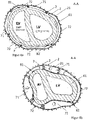
- Figures 4a and 4b show a section through the heart (61) and a part of the device for supporting the function of a heart (61) along the line AA in figure 3 .
- the following layers are shown from the outside in: The shell (2) with a membrane (21), a shell (7) with at least one expandable unit (71, 72), a sensor (81), an electrode (82) and the Heart (60) in transverse section.
- Three augmentation units (71) and three positioning units (72) are shown as examples.
- the expandable units (71, 72) are shown in the non-expanded state.
- the augmentation units (71) are shown in an expanded state.
- the at least one expandable unit (71, 72) is located in an area adjacent to a heart chamber.
- An expansion of the at least one expandable unit (71, 72) can reduce the volume of the heart chamber and thus leads to blood being ejected from the chamber.
- the at least one sensor (81) or the at least one electrode (82) is attached at a point at which at least one parameter of the heart (61) can be measured.
- An electrode (82) can be placed at a location where the heart muscle can be stimulated.
- a sensor (81) and an electrode (82) are shown as an example on the expandable units (71,72).
- the sensors (81) and/or the electrode can also be in the wall of an expandable unit (71,72), on the inside or outside of the sleeve (7), in the sleeve (7) or on the shell (2). to be appropriate. Two, three, four, five or more sensors and/or electrodes can also be attached to the cover.
- FIG 5 shows a delivery system (100) with the help of which the device for supporting the function of a heart can be implanted.
- the delivery system (100) consists of a catheter (103) which has a lumen.
- the catheter (103) is an elongate tubular member into which the device for assisting the functioning of a heart can be loaded in a compressed state.
- the cross section of the catheter (103) and/or the lumen can be round, oval or polygonal.
- the delivery system (100) can further comprise a guide wire (101) and/or a dilation element.
- the dilating element may be a soft, tapered tip (102) with a shaft.
- the guide wire (101) can be passed through a puncture in the chest wall (65) between the ribs (64) and the pericardium (6).
- the soft cone-shaped tip (102) can have a round, oval, or polygonal lumen in the center.
- the soft conical tip (102) can be pushed over the guide wire (101) and the puncture can be dilated without injuring the epicardium.
- the distal section of the catheter (103) of the delivery system (100) can be passed through the dilated opening.
- a first closure element (51, 52) of the pericardial closure can be slipped on or otherwise fastened to the distal end of the catheter (103).
- the catheter (103) can be plugged onto a cone (55) located at the end of the first closure element (51, 52).
- Another embodiment is not shown, in which there is a cone on the side of the catheter and the first closure element can then be slipped onto this.
- the catheter (103) with the attached first closure element (51, 52) of the pericardium closure can be guided over the shaft of the soft tip (102) and introduced into the pericardium (6).
- the catheter (103) and the first sealing element (51, 52) of the pericardial seal can be uncoupled parts. In this case, initially only the catheter (103) is inserted into the pericardium (6) and the first closure element (51, 52) can then be pushed over the catheter into the pericardium (6) or through the lumen of the catheter (103) in the pericardium (6) be deployed.
- the first closure element (51, 52) can be a self-expanding closure element and can unfold in the pericardium (6).
- a non-expandable part (51) of the first closure element contains a self-expanding sealing lip (52) or a sealing lip (52) which can be applied when the first closure element (51, 52) is inserted and spreads open in the pericardium (6).
- the first closure element (51, 52) can expand into a mushroom-like or umbrella-like shape.
- a second closure element (53, 54) can be introduced via the catheter (103) or deployed through the catheter (103).
- the second occlusion member (53, 54) can be moved over the catheter (103) of the delivery system (100) to the distal end of the delivery system (100) and can then be coupled to the first occlusion member (51, 52).
- the second closure element (53, 54) can be expandable or non-expandable.
- the second closure element (53, 54) can be coupled to the first closure element (51, 52).
- the second closure element (51, 52) is preferably self-expanding and, in an expanded form, can assume a mushroom-like or umbrella-like shape.
- the second closure element (53, 54) can be secured with the first closure element (51, 52). Shown in figure 5 is a screw mechanism.
- the catheter (103) of the delivery system (100) can remain on the cone (55) of the first closure element (51) or remain in the lumen of the closure element (51, 52).
- the shell with the at least one sensor or the at least one electrode and/or with the at least one expandable unit can be inserted through the lumen of the catheter (103 ) are introduced.
- the shell is preferably self-expanding and at least partially encloses the heart (61) after expansion.
- a predetermined breaking point (104) can be located on the delivery system (100) and/or on the catheter (103) for this purpose. Preferably, one or more break points (104) are located along a longitudinal axis of the delivery system (100).
- the predetermined breaking point (104) can represent a predetermined breaking line. If the feed system (100) is broken open along a predetermined breaking point (103), the feed system (100) can be divided, unrolled and removed.
- the delivery system (100) can also comprise gripping elements (105) with the aid of which a force can be exerted on the delivery system (100).
- a force directed laterally from the catheter (103) of the delivery system (100) can preferably be exerted with the gripping elements (105) and is suitable for breaking open the predetermined breaking point (104).
- figure 6 shows a step of the implantation of the device according to the invention.
- the shell (2) which is preferably self-expanding is, are passed through the lumen of the catheter (103) of the delivery system and the lumen of the first closure element (51).
- the expansion of the shell (2) begins. Shown in figure 6 is also the second closure element (58, 59) before it has been coupled to the first closure element (51, 52).
- the second closure element (58, 59) is an annular element (58), for example a nut, on the distal side of which a sealing washer (59) can be attached.
- the second closure element (58, 59) can be expandable or non-expandable.
- the second closure element (58, 59) can be slid on the catheter (103).
- the first (51, 52) and the second closure element (58, 59) have threaded sections which can be screwed together.
- figure 7 shows a step of the implantation of the device according to the invention.
- the first closure element (51, 52) is coupled to the second closure element (53). This can seal off the pericardium (6).
- the expandable shell (2) is partially located in the pericardium (6) and can be expanded.
- figure 7 shows markings (25) applied to the shell (2).
- the device according to the invention generally includes at least one mark (25) capable of facilitating correct placement of the shell (2).
- the marking (25) can be an optical marking, in particular a colored marking.
- the marking (25) can be a phosphorescent or fluorescent marking that makes it easier to see in a dark environment. Such environments can be in the operating room itself and can be caused by shadows, among other things. Such environments can also be inside a patient's body.
- the marking (25) can be made from a material that can be displayed using imaging methods. Suitable imaging methods include X-ray methods, CT methods, and MRI methods.
- the marking (25) can consist of a radiopaque Material shaped than the material of neighboring regions.
- the mark (25) can take a mark in the form of a point, a circle, an oval, a polygon or the form of a letter. Other shapes can be surfaces created by connecting dots. For example, the shape can be a crescent or a star.
- the marking (25) can be attached to the shell (2) or attached to an envelope.
- the marking can be in the form of a line.
- the line can start from an upper edge of the shell (2).
- the line can run from an upper edge of the shell (2) to a point at the lower tip of the shell (2).
- the line can run from the top edge of the shell perpendicular to the bottom tip of the shell (2).
- the starting point of the line at the top edge of the shell (2) may be at a point which, when implanted, is near or at an area at the level of the septum of the heart.
- the marking (25) can be located at crossing points of the mesh or the grid. If the shell (2) consists of a shell in which holes have been formed, the marking (25) can be incorporated into the shell. For example, a hole can be made with a predefined shape, which then serves as a marker (25).
- the delivery system and/or the catheter (103) of the delivery system may include one or more markers (106).
- a mark (106) on a delivery system can be shaped like a mark on a tray.
- the marker (106) can be in the form of a point or in the form of a line.
- a marking (106) in the form of a line can be a line at least partially describing a circumference of the delivery system.
- a mark (106) in the form of a line can be a longitudinal line along an axis of the delivery system.
- a mark (106) in the form of a line can be a straight line or a meandering line.
- a marking (106) in the form of a line can be an oblique line on a catheter (103) of a delivery system.
- a marking (103) can facilitate orientation of the delivery system during implantation.
- a mark (103) on the delivery system may align with a line on a medical be implants.
- the medical implant can be a device to support the function of a heart that can be compressed. In a compressed state, the device can be placed in a delivery system.
- One or more markings (25) on or on the device can be registered with one or more markings (106) on or on the delivery system.
- markings (25, 106) facilitate the orientation of a medical implant.
- Markings (25) can also be located along an axis of a medical implant. Such markings (25) can be helpful for tracking the progress of the deployment of a medical implant from a delivery system.
- the delivery system and/or a catheter (103) can be made of a transparent material, which allows the medical implant to be seen during insertion.
- FIG 8 shows the fully expanded configuration of the shell (2) and a sheath (7) of the device according to the invention.
- the shell (2) is formed from a latticework or wire mesh which has struts in the form of brackets or loops (26, 28) on the upper edge and/or on the lower edge of the shell (2). If the shell (2) is formed from a shell jacket in which holes have been formed, the shell (2) can be designed at the upper edge and/or the lower edge in such a way that at least one bracket is located at the upper edge and/or the lower edge Edge of the shell (2) is located.
- the shell (2) shown comprises a cover (7) which is placed in the shell (2).
- At least one expandable unit can be located on the cover (7) and the shell (2).
- the sleeves can be attached to the loops (26, 28) or brackets of the shell (2).
- a cover can be hung on the loops (26, 28) or brackets of the shell (2).
- the cover (7) can have at least one pocket (27) which can be slipped over at least one loop (26, 28) or at least one strap.
- Another embodiment can be a shell (7) comprise, which protrudes over the shell (2) and which is then turned inside out at the upper edge of the shell (2) around the brackets/loops (26) and/or at the lower edge.
- the inverted portion of the sheath (7) can be connected through the latticework or wire mesh to the non-inverted portion of the sheath.
- the inversion can be welded or glued through the lattice work or the wire mesh.
- This inversion can also form a pocket (27) surrounding all or part of the cover (7), which pocket can be hooked into the upper edge and/or the lower edge of the shell (2). Fastening by turning part of the cover around the upper edge of the shell enables the cover to be fixed in the shell with a precise fit.
- the wrapping of the sleeve around the top edge of the shell also protects the tissue from possible damage from the top edge of the shell.
- the sheath (7) can be made of plastic, polymer, caoutchouc, rubber, latex, silicone or polyurethane.
- the casing (7) can have a thickness of 0.1 mm to 1 mm, preferably 0.2 mm to 0.5 mm.
- the shell (2) can have an opening at the lower end.
- a part of the cover (7) can protrude through this opening, for example between 3 mm and 2 cm of the cover can protrude.
- the sleeve (7) can also be open at the bottom, which improves fluid exchange from the space inside the sleeve (7) to the space between the shell (2) and the pericardium (6).
- pericardial fluid can flow in and out through the opening in the sleeve (7).
- the upper edge of the shell (2) preferably runs parallel to the plane of the heart valve, but can have areas of a recess (22).
- the recess (22) in the shell (2) may be necessary for anatomical reasons, for example in order not to compromise the inferior vena cava, which runs from dorsal in the direction of the right atrium of the heart. Compromise of the inferior vena cava would result in inferior inflow congestion (obstruction of filling of the right atrium).
- a recess (22) may also be required due to other anatomical or cardiac structures. If the shell (2) is designed as a latticework or wire mesh, the recess (22) by subsequent cutting off of struts or wires.
- a manufacturing process can also be selected in which the recess (22) does not have to be manufactured afterwards.
- the wire winding can be adjusted in such a way that the wires are selected to be shorter at the point of the recess (22) and the crossing points move closer together.
- the recess (2) can be made by suitably cutting the tube to size and appropriately modifying the slotting. The slitting can be adjusted so that the number of cells in the shell (2) remains the same despite the recess (22). This may be necessary for stability reasons.
- the slitting of the tube can be modified in such a way that one, two or three rows of cells are omitted at the location of the recess (22).
- the sleeve (7) can be adjusted to the recess (22).
- the recess can have a length of 2 cm, 3 cm, 4 cm, 5 cm, 6 cm, 7 cm or more along the upper edge of the bowl.
- the depth of the recess measured from the imaginary uninterrupted upper shell edge to the point of the recess which is closest to the heart tip, can be between 1 mm and 40 mm, in particular between 3 mm and 15 mm. In the circumferential direction, the recess is positioned where the inferior vena cava opens into the right atrium.
- the recess can be arcuate, semicircular, rectangular or polygonal.
- the recess (22) can be so long that it corresponds to the circumference of the upper edge of the shell (2).
- the recess (22) can then begin and end at the point on the upper edge of the shell (2) which is opposite the cardiac structure to be recessed, for example the inferior vena cava.
- the result can be that the recess (22) defines a plane which is tilted to the plane of the heart valve and which is 1 mm to 40 mm, in particular 3 mm to 15 mm, lower than if the upper edge of the Shell (2) would run parallel to the heart valve plane.
- the casing (7) has a recess (22) which essentially matches the recess (22) in the shell (2) in terms of its shape, position and dimensions. coincides, which exposes the anatomical area around the inferior vena cava. This prevents the inferior vena cava from being compromised by the sheath (7) and consequently preventing filling of the right atrium.
- the recesses (22) in the cover (7) and shell (2) can be brought into congruence with one another.
- the shell (2) has several markings (25). As already described, these markings (25) can take different forms or positions. In the present case, the markings (25) are attached to an upper edge and to the lower tip of the shell (2).
- one, two, three, four or more extension struts (23) can be attached to the shell.
- the extension struts represent an extension of the shell (2) in the direction of the heart's longitudinal axis.
- the extension struts (23) can run in the direction of an imaginary heart apex, touch there or not quite touch and from there protrude away from the heart in the direction of the heart's longitudinal axis.
- the extension struts (23) can be collected in a common sleeve.
- the extension struts and/or the sleeve can be connected to the cable of the device, for example by gluing.
- the extension struts (23) can be used to fix the shell in the axial direction.
- the extension struts (23) restrict the rotation of the shell around the longitudinal axis of the heart only to a limited extent. If the shell is made of wire mesh, the extension struts (23) can represent the extended ends of wires. The extension struts (23) and the wire mesh are therefore one part. If the shell (2) consists of a latticework made from a slotted tube, the latticework with the extension struts (23) can be made from just one tube by suitable cutting. The lattice work and the extension struts (23) are thus one part.
- the extension struts (23) and the shell (2) can also be in several parts, with which the extension struts (23) are attached to the shell (2) after it has been manufactured, for example by a Suspension mechanism or by material connection (welding, gluing).
- the length of the extension struts (23) can be between 1 cm and 10 cm, in particular between 4 cm and 7 cm.
- the shell (2) can only include the recess (22) described above and no extension struts (23). Alternatively, the shell (2) may include both the recess (22) described above and the extension struts (23) described above. The shell (2) can also include only the extension struts (23) described above and no recess (22).
- FIG 9 shows a step of the implantation of the device according to the invention.
- the heart is not shown.
- the first closure element (51, 52) and the second closure element (53) of the pericardial closure are coupled to one another.
- the device for supporting the function of a heart has already been partially deployed from the delivery system.
- a self-expanding shell (2) into which a cover (7) has been introduced is shown.
- Expandable units (71) in the form of bellows-shaped chambers, a sensor (81) and an electrode (82) are attached to the cover.
- the shell (2) and sleeve in this embodiment are essentially the same as the shell and sleeve, respectively figure 8 .
- the shell (7) can be the underside of the expandable units (71).
- the expandable units (71) can be adapted to the shape of the heart, the shell (2) and/or the envelope (7).
- One, two, three, four, five, six, seven or more expandable units (71) can be applied to the cover (7).
- the expandable units (71) can exert pressure on the heart muscle. This pressure is preferably applied to the heart muscle in areas below which there is a ventricle, but always below the level of the heart valve.
- the expansion of the expandable units (71) pushes the heart muscle up in the direction of the heart's longitudinal axis to the level of the heart valve. If the expandable units (71) are arranged in the upper area of the sleeve (7) and the shell (2), the heart muscle is pressed perpendicularly to the longitudinal axis of the heart when the expandable units (71) expand. Pressure is then applied to the heart muscle parallel to the plane of the heart valves (laterally on the ventricles).
- the expandable units (71) can also be positioned at any position between the lower edge and the upper edge of the sleeve (7) and shell (2), whereby the pressure of the expandable units (71) during their expansion is proportionate in the direction of the longitudinal axis of the heart and proportionately parallel to the heart valve level.
- expandable units (71) are shown which are located at the upper edge of the envelope (7). When the expandable units (71) expand, the pressure therefore acts as parallel as possible to the plane of the heart valve.
- the opposing force on the device in the direction of the longitudinal axis of the heart is kept low as a result. A displacement of the device away from the heart in the direction of the longitudinal axis of the heart (dislocation), caused by expansion of the expandable units (71), is thereby minimized.
- the self-expanding shell (2) and the cover (7) in this representation have a recess (22) in order not to compromise the inferior vena cava in the implanted state of the device.
- the size, shape and position of the expandable units (71) can be adapted to the recess (22) in the shell (2) and the cover (7), so that they do not fill the recess either in the expanded or in the non-expanded state (22) cover.
- extension struts (23) which fix the shell (2) in the axial direction to the cable and thus stabilize the device as a whole.
- the extension struts (23) can be connected to the cable of the device.
- a part of the extension struts (23) can also remain in the pericardial closure or outside of the closure elements (51, 52, 53) of the pericardial closure after the implantation.
- the extension struts (23) can have holes, straps, loops or angled ends at their ends, which facilitate minimally invasive explantation of the shell (2) and the sleeve (7).
- the angled ends, holes, brackets or loops do not prevent the extension struts (23) from being fixed in the cable.
- ends of the extension struts (23) may be located within the cable.
- the cable can be cut off approximately at the level of the ends of the extension struts (23) and the shell (2) with the cover (7) can be closed at the ends of the extension struts (23) by the locking elements (51, 52, 53). be pulled out of the pericardium (6).
- a tool can be coupled to the angled ends of the extension struts (23) or to the holes, straps or loops located at the ends of the extension struts (23).
- FIGS 10a -c show different views of a pericardial closure (5).
- the pericardial closure (5) serves to avoid the loss of pericardial fluid, or also the possibility of being able to apply artificial pericardial fluid, also with the addition of medication or other therapeutic agents. Avoiding loss of pericardial fluid also serves to avoid adhesions of the system to the epicardium.
- the pericardial closure (5) generally consists of a first closure element (51) and a second closure element (52).
- the first occlusion member (51) has a central lumen and the second occlusion member (53) has a central lumen.
- the first closure element (51) can be coupled to the second closure element (53).
- the coupled pericardial closure (5) After coupling the first closure element (51) to the second closure element (52), the coupled pericardial closure (5) has a lumen running through the pericardial closure (5).
- the lumen can exclusively formed by the central lumen of the first closure member (51) or the lumen may be formed solely by the central lumen of the second closure member (53). In another embodiment, the lumen can also be formed from the two lumens of the two coupled closure elements (51, 53).
- a grommet, O-ring, labyrinth seal, or other sealing element (56) may be located within the lumen.
- a sealing element (56) in the lumen of the pericardium seal can seal the pericardium seal (5) against an object protruding through the pericardium seal (5).
- a cable can be passed through the pericardial seal (5), which is then sealed against the pericardial seal (5).
- a sealing element (56) in the lumen can serve not only to seal, but also to fix an object protruding through the lumen of the pericardial closure.
- the sealing element (56) can be attached to both closure elements (51, 53) or only to one of the two closure elements (51, 53).
- the first closure element (51) can be secured to the second closure element (53) with the aid of a mechanism.
- a mechanism for securing a first closure member (51) to a second closure member (53) may include a screw mechanism or a clamp mechanism.
- a mechanism for securing a first locking element (51) with a second locking element (53) can also include a bayonet lock.
- the first closure element (51) and the second closure element (53) can be made of the same material or of different materials. Suitable materials for the first closure element (51) and/or the second closure element (53) include plastics, metals, ceramics or combinations thereof.
- a first sealing lip (52) can be attached to the first closure element (51).
- the first sealing lip (52) can be part of the first closure element (51) or it can be attached to the first closure element (51).
- a second sealing lip (54) can be attached to the second closure element (53).
- the second sealing lip (54) can be part of the second closure element (53) or it can be attached to the second closure element (53).
- the first sealing lip (52) and the second sealing lip (54) can be formed from the same material or from different materials.
- One or both sealing lips (52, 54) can be part of the respective closure element (51, 53) and can be formed from the same material as the associated closure element (51, 53).
- the first sealing lip (52) and/or the second sealing lip (54) may be formed of plastic (preferably an elastomer), caoutchouc, gum, silicone, latex, or a combination thereof.
- the first sealing lip (52) and/or the second sealing lip (54) can be disc-shaped.
- the first sealing lip (52) and/or the second sealing lip (54) can have a concave or convex curve.
- Curved sealing lips (52, 54) can adapt better to the anatomical conditions.
- the pericardium is convex in shape at the apex of the heart. Since the sealing lips (52, 54) are bent in the shape of the anatomically present shape of the pericardium, an improved anatomical fit of the pericardium seal (5) can be achieved. Improved sealing properties can also be achieved with curved sealing lips (52, 54).
- the first sealing lip (52) and/or the second sealing lip (54) can have reinforcements.
- the first sealing lip (52) and/or the second sealing lip (54) can have increased flexibility as the radial distance from the lumen of the pericardium seal increases.
- Increased flexibility in the edge areas of a sealing lip (52, 54) can promote the sealing properties of the sealing lip (52, 54) and also the anatomically correct positioning of the sealing lip (52, 54). Increased flexibility in the edge areas of a sealing lip (52, 54) can be achieved through the choice of material.
- Each of the sealing lips (52, 54) can consist of one material or of several materials.
- Reinforcements in a sealing lip (52, 54) can be concentric reinforcements or radial reinforcements. Reinforcements can be achieved by changing material thicknesses or by introducing a reinforcing material.
- the reinforcing material can be the same material as the base material of the sealing lip (52, 54) which has been converted into a different form of material.
- regions cannot should be strengthened weakened by converting the material of the sealing lip (52, 54) into a weaker form of the material.
- the material can be weakened by exposure to energetic radiation, such as heat. Reinforcements of the material can also be achieved by applying material, whereby the applied material can be the same material as the base material of the sealing lip (52, 54), or the applied material can be a different material than the base material of the sealing lip (52, 54). can represent.
- Suitable materials for reinforcing parts of a sealing lip (52, 54) are metals, ceramics, rubber and or a combination thereof.
- a coupling mechanism can be located on one of the two closure elements (51, 53) which enables a closure element (51, 53) to be coupled to the delivery system or to a catheter of the delivery system.
- the coupling mechanism can consist, for example, of a cone (55) located on the first closure element (51) onto which the delivery system or a catheter of a delivery system can be clamped. The clamping effect can be achieved, for example, by the diameter of the cone (55) being larger than the luminal diameter of the delivery system.
- the coupling mechanism for coupling the pericardial closure (5) to the delivery system can also be located on the second closure element (53).
- the coupling mechanism can also be present as a separate component next to the closure elements (51, 53) and can connect the delivery system to one of the two closure elements (51, 53) of the pericardial closure (5).
- Other embodiments of the coupling mechanism include a non-conical (e.g. cylindrical) extension on one of the closure elements (51, 53) to which the delivery system can be applied or glued, or an embodiment in which the catheter of the delivery system and a closure element are a single integral part represent. In the latter embodiment, after the pericardium closure (5) has been successfully introduced and secured, the catheter can be separated from the closure element (51, 53) of the pericardium closure (5) by means of a predetermined breaking point.
- Engaging elements (57) on one or both closure elements (51, 53) can be used to exert a force on one or both closure elements (51, 53) which is suitable for coupling and/or securing the closure elements (51, 53).
- Engaging elements (57) on one or both closure elements (51, 53) can be holes, indentations or elevations.
- the engaging elements (57) can be attached circumferentially around the closure element (51, 53) at the same distance from one another. The circumferential distance between the engaging elements (57) can also be different. In the Figures 10a-c six engaging elements (57) are shown at a uniform circumferential distance from one another.
- the six engagement elements (57) are attached to the annular closure element (53) at an angular distance of approximately 60°. With two, three, four, five, six, eight or more evenly arranged engagement elements (57), the angular spacing can be 180°, 120°, 90°, 72°, 60°, 45° or less.
- the engaging elements (57) can also be arranged irregularly.
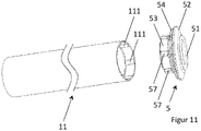
- FIG 11 shows a pericardial closure (5) and a tool (11) for securing a pericardial closure (5).
- the pericardial closure (5) shown essentially corresponds to that in figure 10 closure shown.
- the tool (11) is exemplified as an elongate tubular tool.
- elements (111) At the distal end of the tool (11) there are elements (111) which can be at least partially engaged with the engaging elements (57) of a closure element (53).
- the tubular tool (11) has six inwardly pointing projections (111) at the distal end which engage with the six engaging elements (57) of the closure element (53), in this case six indentations on the closure element (53). can be brought.
- the tool (11) has essentially the same number of elements (11) which are complementary to the engaging elements (57) of the closure element (53).
- This in figure 11 shown tool (11) is a tubular tool consisting of a completely surrounding tube.
- the tubular element of the tool (11) can also be a half-tube, quarter-tube, or one-third tube.
- only one stem or several stems can be attached to a distal ring-shaped tool.
- a stem may extend longitudinally from the annular tool.
- a stem can also extend laterally away from a longitudinal axis of the tool.
- Other embodiments of the tool (11), which are also not shown, can be in the form of a modified ring wrench or a modified open-end wrench.
- FIG 12 shows a connector system consisting of two connector parts (90, 92).
- the device for supporting the function of a heart consists of a shell with at least one sensor or at least one electrode and/or at least one expandable unit, the at least one sensor or electrode and/or the at least one expandable unit being connected to a supply unit.
- the at least one sensor or the at least one electrode and/or the at least one expandable unit can be connected directly to the supply unit.
- the at least one sensor or the at least one electrode and/or the at least one expandable unit can be connected to the supply unit via a cable (4).
- the at least one sensor or the at least one electrode and/or the at least one expandable unit can be connected directly to the supply unit via the cable (4), or the at least one sensor or the at least one electrode and/or the at least one expandable unit can be connected to the supply unit must be connected.
- the supply unit can include a plug part (92).
- the plug part (92) can be attached directly to the supply unit.
- the plug part (92) can be connected to the supply unit via a cable (4).
- the at least one sensor or the at least one electrode and/or the at least one expandable unit can include a cable (4). At the end of the cable (4) there can be a plug part (90).
- the plug part (90) at the end of the cable of the at least one sensor or the at least one electrode and/or the at least one expandable Unit can be coupled with the connector part (92) of the supply unit.
- the connector part (90) of the sensor or the electrode and/or the at least one expandable unit can be a male connector part or a female connector part.
- a female connector on the side of the sensor or the electrode and/or the at least one expandable unit may be advantageous because the female connector, unlike the male connector, does not include pins (951) or other terminals that protrude and can break. If the supply unit needs to be replaced, the connector system must be uncoupled and a new supply unit must be coupled into the connector part (90) of the sensor or the electrode and/or the at least one expandable unit.
- pins (951) or other connections can lead to breakage of pins (951) or other connections. If these pins (951) or connectors are on a male connector part on the side of the shell with the at least one sensor or the at least one electrode and/or the at least one expandable unit, the shell may need to be replaced.
- a female connector part on the side of the shell with the at least one sensor or the at least one electrode and/or the at least one expandable unit can be advantageous since pins (951) or other connections on a female connector part cannot break.
- the connector system (90, 92) consists of two connector parts.
- the device according to the invention consists of a connector system (90, 92) for the at least one sensor or the at least one electrode and/or the at least one expandable unit or multiple connector systems.
- the connector system (90, 92) shown is a connector system that includes connections for supplying the at least one sensor or the at least one electrode and the at least one expandable unit.
- the number of connections depends on how many sensors or electrodes and how many expandable units are used, the number not being directly related to the number of sensors or electrodes and/or the number of expandable units must correlate. Bifurcations of lines are possible on both sides of the connector system (90, 92) and a pneumatic or hydraulic line can supply one, two, three, four, five, six or more fillable chambers.
- the connector system (90, 92) shown includes four hydraulic or pneumatic connections (93, 94) and a connection for electrical lines (95, 96).
- the connection shown for electrical lines (95, 96) has 16 connection elements in the form of pins (951) and pin sockets (961). More or fewer connections for electrical lines (95, 96) and/or pneumatic or hydraulic lines (93, 94) can be present in a plug system.
- connection elements there can be one, two, three, four, five, six, seven, eight, nine or ten connections for pneumatic or hydraulic lines (93, 94). There may be one, two, three, four, five, six, seven, eight, nine, ten, twelve, fourteen, sixteen, twenty or more electrical wire (95, 96) terminals. There can be one, two, three, four, five, six, seven, eight, nine, ten, twelve, fourteen, sixteen, twenty or more connection elements in the form of pins (951) and pin sockets (961) within an electrical connection for electrical lines (95, 96). However, the number of connection elements in the form of pins (951) and pin sockets (961) is identical for the respective connection pair for electrical lines (95, 96).
- Each of the ports (93, 94, 95, 96) in one or both of the connector parts of the connector system (90, 92) has its own seal (931, 952).
- the seal (931, 952) of the individual connections (93, 94, 95, 96) can be a sealing strip or a sealing ring.
- the connector system (90, 92) can additionally or only have a seal inside the connector system (973) or around the connector system.
- a seal over the connector system can be a sealing tape or a sealing ring.
- the connector parts (90, 92) can be coupled together to form the connector system (90, 92).
- the plug parts (90, 92) can also have a guide nose (972) and a guide groove (974) own.
- the guide nose (972) and the guide groove (974) can prevent incorrect coupling of the two plug parts and/or twisting of the plug parts during the coupling process.
- the coupled plug parts (90, 92) can also be secured with a mechanism (971).
- a mechanism (971) can be a screw mechanism or a clamping mechanism or a bayonet lock.
- a mechanism for securing the mated connector system (90, 92) may also be a nut, clamp, latch or snap lock externally attached to the connector system. Securing the connector system (90, 92) is advantageous because accidental or accidental partial or complete opening of the connector system (90, 92) can interrupt the supply of the at least one sensor or the at least one electrode and/or the at least one expandable unit.
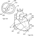
- figure 13 shows a model for creating a coordinate system and dimensioning the shell and hull.
- the creation of a coordinate system can facilitate the manufacture of a device to support the function of a heart, since the dimensions of the cover and shell, the position for the at least one sensor or an electrode and/or the at least one expandable unit and/or the at least one marking are exact can be defined.
- FIG 13a shows a heart (61) with anatomical landmarks. Shown is the heart (61) with the aortic arch (AO) (with the branching head, neck and collarbone arteries (TR, CL, SCL)) emanating from the left ventricle (LV) and that emanating from the right ventricle (RV). Pulmonary Artery (PU). Also shown are portions of the inferior vena cava (IVC, inferior vena cava) and superior vena cava (SVC). The dashed line (601) represents the position of the flap level. By dropping the perpendicular (603) from this plane (601) through the distal-most apex point is defined the apex point (604).
- AO aortic arch
- TR, CL, SCL branching head, neck and collarbone arteries
- PU Pulmonary Artery
- IVC inferior vena cava
- SVC superior vena cava
- CT or MRT image data can be used that were recorded at specific points in time during a heart cycle (ECG-triggered image data acquisition).
- image data are available that were recorded during the diastole of the cardiac cycle, in particular at a point in time between 50% and 100% of the time profile of the diastole, in particular between 75% and 80%, in particular at 78% of the time profile of the diastole.
- Image data recorded at a point in time during the systole of the heart cycle or without ECG triggering can also be used.
- the device according to the invention consists of a shell into which a shell with at least one sensor or an electrode and/or a shell with at least one expandable unit can be inserted.
- the dimensioning of the shell and/or the shell can be based on the 3D image of the heart reconstructed from CT or MRT image data.
- the shell and/or shell can be smaller, the same size or larger than the 3D image of the heart.
- the shell and/or shell may be spaced from the surface of the 3D image or scaled to the surface of the 3D image.
- the surface of the 3D image can correspond to the epicardium or the pericardium of the real heart.
- the shell can have a constant distance of 1 mm to 10 mm from the 3D image, in particular 2 mm to 8 mm, in particular 3 mm to 5 mm.
- the distance between the 3D image and the shell can also vary locally within the limits of 1 mm and 10 mm, in particular from 2 mm to 8 mm, in particular from 3 mm to 5 mm.
- the size of the shell may be determined by spatial stretching of the 3D image of the heart surface, in particular where the spatial stretching factor is in a range of 1.01 to 1.2.
- the shell can have a constant distance of 1 mm to 7 mm from the 3D image, in particular 2 mm to 5 mm.
- the distance between the 3D image and the shell can also vary locally within the limits of 1 mm and 7 mm, in particular from 2 mm to 5 mm.
- the size of the envelope can be determined by spatial stretching of the 3D image of the heart surface, in particular with the spatial stretching factor being in a range from 1.004 to 1.1, preferably in a range from 1.005 to 1.06.
- the upper edge of the shell and/or sheath (602) may be parallel to the plane of the valve at a downward offset distance from the plane of the valve in the direction of the apex of 1 mm to 30 mm, 3 mm to 20 mm, 5 mm to 10 mm, preferably 5mm
- the top edge of the shell and/or casing is in Figure 13a shown by line (602).
- the lower edge of the shell and/or sheath (605) may be parallel to the plane of the valve at a distance from the most distal point (604) of 1mm to 30mm, 3mm to 20mm, 5mm to 10mm, preferably 5 be mm.
- Figure 13b shows a section plane BB along the in Figure 13a line (602) shown, i.e. along the line corresponding to the top edge of the shell.
- the right chamber of the heart (right ventricle, RV) and the left chamber of the heart (left ventricle, LV), the heart wall, and the septal wall separating the heart chambers are shown.
- Points (608) and (609) are defined as the intersections of the centerlines of the heart wall with the septal wall.
- Point (608) is also referred to as the anterior crossing point of the heart wall midlines with the septal wall.
- Point (609) is also referred to as the posterior crossing point of the heart wall midlines with the septal wall.
- the midpoint on a line connecting points (608) and (609) is defined as point (607).
- a polar coordinate system can be defined using these points.
- the z-axis (606) of the polar coordinate system is defined as the line connecting the distal-most point (604) to the midpoint (607) of the line connecting points (608) to (609).
- the position for the at least one sensor or one electrode and/or the at least one expandable unit and/or the at least one marking can be defined with the aid of the coordinate system.
- figure 14 shows a shell and/or casing of the above related to figure 13 described coordinate system.
- Figure 14a shows a 3D model (611) of a shell or shell with the z-axis (606) passing through the distal-most point (604) and the midpoint (607) of the line connecting points (608) with (609 ) connects.
- the dashed line connecting points (608) to (609) along an outer perimeter of the shell or shell represents the location of the septal wall of the heart projected onto the shell/shell.
- Longitudinal lines (613) projected onto the shell/cover run along these angle specifications up to the apex of the heart (604).
- Contour lines (614) are drawn at intervals of 15 mm increments.
- the contour lines (614) and planes are perpendicular to the z-axis (606).
- the dotted-dashed line (615) represents a cutting line where the 3D shape (611) can be cut open and then unrolled.
- Figure 14b shows an unrolled shell or sleeve (612) along line (615) in Figure 14a was cut and then rolled out.
- Positions (608, 609) and lines (613, 614, 615, 616) shown represent the same positions and lines shown in Figure 14a are shown.
- figure 15 shows a shell (7) with at least one expandable unit (71, 72).
- the 3D shape of the shell (7) in Figure 15a is similar to that associated with Figure 14a 3D model explained and shows a coordinate system as described above with degrees of longitude (613), degrees of latitude (614), the line of progression of the septum (616) and the line of intersection (615) for the representation the 2D unrolling.
- the shell (7) can at least partially enclose a heart.
- the shell (7) can at least partially have the shape of a heart.
- the shell (7) can have a similar shape as the shell.
- the shell can be placed in the shell.
- the shell can be made of plastic, polymer, caoutchouc, rubber, latex, silicone, or polyurethane.
- the case can be custom made based on the in Figure 14a explained 3D model are manufactured. Suitable manufacturing processes are, for example, casting or, in particular, thermoforming. During thermoforming, the shell's starting material, which is in the form of plates or foils, is pressed, pulled and/or sucked against a shaping physical 3D model of the heart under the effect of heat, with the shape of the 3D model being transferred to the material.
- the casing (7) can have a thickness of 0.1 mm to 1 mm, preferably 0.2 mm to 0.5 mm.
- the sleeve has a recess (22) which essentially corresponds in shape, position and dimensions to the recess in the shell, which exposes the anatomical area around the inferior vena cava. This prevents the inferior vena cava from being compromised and consequently preventing filling of the right atrium.
- Figure 15a the sleeve (7) with at least one expandable unit (71, 72) is shown as a sleeve (7) with a plurality of chambers.
- Figure 15b shows a 2D unroll of the 3D model Figure 15a .
- unrolling essentially corresponds to in connection with Figure 14b explained unrolling of a 3D model.
- Figure 14b explained unrolling of a 3D model.
- the 3D model in Figure 15a rotated in such a way that a view from above into the shell (7) is made possible.
- four expandable units (71, 72) are shown as an example, three of which are augmentation units (71) and one is a positioning unit (72).
- the expandable units (71, 72) may be structurally similar but may serve different purposes as described above.
- an augmentation unit (71) can be periodically expanded and relaxed so that pressure can be exerted on the heart. This Pressure is applied preferentially to areas of the heart muscle under which there is a ventricle.
- the natural pumping action of the heart is assisted or replaced and the blood in the heart is pumped out of the heart chamber into the efferent artery.
- Pressure exerted on a right ventricle by an augmentation unit (71) causes blood to be ejected from the right ventricle into the pulmonary artery.
- Pressure exerted on a left ventricle by an augmentation unit (71) causes blood to be ejected from the left ventricle into the aorta.
- each of the augmentation units (71) is supplied by its own line (41).
- the lines (41) are preferably pneumatic or hydraulic lines.
- Other embodiments include one, two, three, four, five, six or more augmentation units (71) supplied with one, two, three, four, five, six or more lines (41).
- the at least one line (41) can be made of plastic, polymer, rubber, latex, silicone or polyurethane.
- the at least one line (41) can run above, next to or below at least one augmentation unit (71).
- the at least one line (41) can preferably run under a positioning unit (72) so that there are no pressure points between the at least one line (41) and the heart wall.
- the at least one line (41) can also run above or next to a positioning unit (72).
- the augmentation units (71) A1, A2 and A3 shown are located in an area at the upper edge of the shell (7) and are each supplied by their own line (41). As in this exemplary embodiment, the augmentation units (71) A1 and A2 can be positioned in such a way that they can support a left ventricle. In this representation, the augmentation unit A2 (71) is adjusted in shape and position so that it does not cover the area of the recess (22). The anatomical position of the inferior vena cava can vary slightly from patient to patient, or other anatomical conditions can make it necessary for other augmentation units (71) or possibly existing positioning units (72) to be adapted to a recess (22).
- the augmentation unit (71) A3 is positioned such that it can support a right ventricle.
- the individual augmentation units (71) A1, A2 and A3 can be expanded individually.
- the augmentation units (71) A1 and A2 can be used to support left heart failure.
- the augmentation unit (71) A3 can be used to support right heart failure.
- the augmentation units (71) A1, A2 and A3 can be used to support bilateral cardiac insufficiency.
- the augmentation units (71) can be expanded synchronously or asynchronously.
- the expansion of the augmentation units (71) can preferably be coordinated with one another so that a natural pumping function of the heart is supported.
- a positioning unit (72) is a unit that can also be expanded.
- a positioning unit is expanded more statically than periodically during operation of the device to support the function of a heart.
- the positioning unit (72) can be expanded to fix the device to the heart and to optimize the fit of the device.
- a positioning unit (72) can also be used to react to changes in the heart muscle. If the heart muscle degenerates or develops, a positioning unit (72) can be further expanded or relaxed to ensure an optimal fit.
- a positioning unit (72) is shown which essentially fills the spaces between the three augmentation units (71) on the sleeve (7).
- the positioning unit (72) can have a lateral distance of 1 mm, 3 mm, 5 mm, 10 mm, 20 mm, 30 mm, 40 mm or more from one or more augmentation units (71). the However, the positioning unit can also be formed independently of the augmentation units. For example, the positioning unit can also only enclose the area near the apex of the heart without filling the gaps between the augmentation units.
- the positioning unit (72) can be supplied with its own line (41), in the case of a chamber that can be filled with fluid, with its own pneumatic or hydraulic line.
- FIG. 7 A positioning unit (72) shown fills in areas between the augmentation units (71).
- the positioning unit (72) shown has projections that protrude into the spaces between the augmentation units (71).
- figure 16 shows an expandable unit (71, 72) in the form of a chamber (710).
- the chamber shown is a bellows shaped chamber (710).
- a bellows-shaped chamber (710) has at least a portion that is in the shape of a bellows. It is preferably a bellows consisting of one, two, three, four, five, six, seven or more folds.
- a fold edge (711) directed outwards can be defined as a fold.
- a fold edge (712) directed inward can be defined as a fold.
- One, several or all creases (711, 712) can be reinforced. Reinforcement of a fold edge (711, 712) is advantageous since the fold edge (711, 712) can be exposed to increased loads due to the expansion and relaxation of the chamber (710).
- a fold edge (711, 712) can be reinforced by a greater wall thickness of the material at the fold edge (711, 712).
- a fold edge (711, 712) can also be reinforced Application of additional material may occur, wherein the applied material may be the same material as the underlying material, or wherein the applied material may be a different material than the underlying material.
- a chamber (710) can have an upper side (713), an underside and a side surface, the side surface preferably being in the form of a bellows.
- the top (713) and/or bottom may be oval, circular, elliptical, or polygonal. The top (713) can have a different shape than the bottom.
- a bellows shaped chamber (710) can be placed in a shell as described above.
- the chamber (710) can be attached or fixed directly in the shell.
- the chamber (710) can be attached to structural elements of the shell, such as a wire of a wire mesh, a strut of a truss, or a structure on a shell shell.
- the chamber (710) can be attached at crossing points of a mesh or lattice work.
- the shell may be covered with a membrane as described above. In these cases the chamber (710) can also be attached to the membrane.
- the membrane can also be an underside of the chamber (710).
- the bellows-shaped chamber (710) can also be attached to a sleeve (7).
- Several bellows-shaped chambers (710) can be attached to a sleeve (7).
- the shell (7) can at least partially have the shape of a heart.
- the shell (7) can have a similar shape as the shell.
- the sleeve (7) can be placed in the shell.
- the cover (7) can be fastened and/or fixed in the shell.
- the cover (7) can also have one or more positioning units.
- the bottom of the chamber (710) can be made of the same material as the shell (7).
- the shell (7) can be part of the chamber (710).
- the shell (7) can form the bottom of the chamber. In such cases, only the side surfaces, which can be bellows-shaped, are applied to a cover (7).
- one Top (713) are attached.
- the top (713) can also be a shell.
- Embodiments consist of two shells (7), with the shells (7) forming the top and bottom of the chambers and side surfaces being formed between the shells. In this case, side surfaces can also be formed by connecting, in particular by welding or gluing, the two casings.
- the casings (7) can be connected to one another, in particular welded or glued, in such a way that a chamber is formed.
- the at least one line that supplies the chamber can, like the chamber, also be formed at least in part by connecting the two casings (7), in particular by welding or gluing the two casings (7).
- One or more sensors or one or more electrodes can be located on one of the two covers (7) or on both covers (7).
- the sleeve (7) with the at least one expandable unit can have at least one pocket on the upper edge and/or on the lower edge.
- the at least one pocket can be placed at least partially over a structural form of a shell.
- the bag can, for example, be placed at least partially over a loop of a wire mesh or a bracket of a latticework.
- the shell (7) with the at least one expandable unit can contain an active substance.
- the shell (7) may contain an antithrombotic agent, an antiproliferative agent, an antiinflammatory agent, an antineoplastic agent, an antimitotic agent, an antimicrobial agent, a biofilm synthesis inhibitor, an antibiotic agent , an antibody, an anticoagulant agent, a cholesterol-lowering agent, a beta-blocker, or a combination thereof.
- the active ingredient is in the form of a coating on the shell (7).
- the shell (7) can also be coated with extracellular matrix proteins, in particular fibronectin or collagen.
- figure 17 shows a shell (80) with at least one sensor (81) and/or at least one electrode (82).
- the 3D shape of the shell (80) in Figure 17a is comparable to the in Figure 14a 3D model explained and shows a coordinate system as described above.
- the sheath (80) can at least partially enclose a heart.
- the shell (80) can at least partially have the shape of a heart.
- the shell (80) with the at least one sensor (81) and/or at least one electrode (82) can have a shape similar to the shell.
- the sleeve (80) can be inserted into the shell.
- the shell (80) can have a recess (22) which essentially corresponds in shape, position and dimensions to the recess in the shell.
- the sheath (80) can be made of plastic, polymer, rubber, latex, silicone or polyurethane.
- the sheath (80) can have a thickness of 0.1 mm to 1 mm, preferably 0.2 mm to 0.5 mm.
- the sleeve (80) can be coated, in particular with a lubricant that reduces the friction between the heart muscle and the sleeve (80) with the at least one sensor (81) and/or the at least one electrode (82).
- the sleeve (80) with the at least one sensor (81) and/or at least one electrode (82) can be introduced instead of or in addition to the sleeve with the expandable units. If the sheath (80) is introduced in addition to the sheath with the expandable units, the sheath (80) can be located closer to the heart than the sheath with the expandable units.
- the sleeve (80) with the at least one sensor (81) and/or at least one electrode (82) can be firmly connected to the expandable units, with the sleeve (80) then forming the upper side of the expandable units.
- the shell (80) with the at least one sensor (81) and/or at least one electrode (82) can also be connected to the shell with the expandable units and/or the shell only at the top and/or bottom edge, with which the Cover (80) can be pressed against the heart muscle through the cover with the expandable units.
- a coating in particular a coating with a lubricant, can also be placed between the shell (80) with the at least one sensor (81) and/or the at least one electrode (82) and the shell with the at least one expandable unit may be present.
- the at least one sensor (81) and/or the at least one electrode (82) can be incorporated, cast or welded into the cover (80), or attached, glued or sewn onto the cover (80).
- the at least one sensor (81) and/or the at least one electrode (82) can be provided with reinforcements that can prevent buckling during compression of the device.
- Figure 17a the shell (80) with at least one sensor (81) and/or at least one electrode (82) is shown as a shell (80) with a multiplicity of sensors (81) and electrodes (82).
- Figure 17b shows a 2D unroll of the 3D model Figure 17a .
- unrolling essentially corresponds to in connection with Figure 14b explained unrolling of a 3D model.
- Figure 17a rotated to allow a view of the shell (80) from above.
- eight sensors (81) or electrodes (82) are shown as an example.
- Other embodiments may include one, two, three, four, five, six, seven, eight, nine, ten, eleven, twelve or more sensors (81) and/or electrodes (82).
- the shell (80) with at least one sensor (81) or at least one electrode (82) can be a network of sensors (81) or electrodes (82).
- the network of sensors (81) or electrodes (82) can at least partially enclose the heart.
- the sensors (81) or electrodes (82) in the network of sensors (81) or electrodes (82) can be connected to each other.
- the shell (80) can function as a support for the network of sensors (81) or electrodes (82).
- the network of sensors (81) or electrodes (82) can also only be partially attached to a cover (80).
- the network of sensors (81) or electrodes (82) can also be placed in a shell as described above without a cover (80).
- the at least one sensor (81) or the at least one electrode (82) can determine a physical or a chemical property of its environment. The property can be recorded qualitatively or quantitatively.
- the sensor (81) can be an active sensor or a passive sensor.
- the at least one sensor (81) can detect at least one parameter of the heart.
- the at least one sensor (81) can be suitable for determining heart rate, heart chamber pressure, systolic blood pressure or diastolic blood pressure.
- the sensor (81) can be suitable for measuring the pressure exerted by an expandable unit on a surface, the pH value, the electrical resistance, the osmolarity of a solution, the oxygen saturation or the flow through a vessel.
- the at least one sensor can also be used as an electrode.
- the at least one electrode (82) can be suitable for stimulating areas of the heart and/or for measuring the action potential on the heart muscle during the excitation process.
- the at least one electrode (82) can be suitable for stimulating the heart muscle with the aid of electrical impulses. Electrical stimulation can cause a heart muscle to contract.
- the at least one electrode (82) can be a pacemaker electrode.
- the electrode (82) can be an extracardiac stimulation electrode.
- the heart muscle can be stimulated with an electrode (82) before, during or after support of the pumping function of the heart by a shell with at least one expandable unit.
- the expansion of an expandable unit can take place before, during or after stimulation with an electrode (82).
- the device for supporting the function of a heart can only be operated with at least one expandable unit or only by stimulation with at least one electrode (82). Simultaneous operation of the at least one expandable unit and the at least one electrode (82) can be synchronous or asynchronous.
- the at least one electrode can also be used as a sensor.
- the at least one sensor (81) or the at least one electrode (82) can be attached to the sleeve (80).
- the at least one sensor (81) or the at least one electrode (82) can be glued, sewn or welded onto the cover (80).
- the at least one sensor (81) or the at least one electrode (82) can attached to the shell (80), preferably welded in place.
- the at least one sensor (81) or the at least one electrode (82) can be positioned in such a way that they lie exactly over an augmentation unit or not lie exactly over an augmentation unit.
- the at least one sensor (81) or the at least one electrode (82) can also be positioned so that they lie exactly over a positioning unit or are located in an area below which there is no expandable unit. If the sleeve (80) is not present, at least one sensor (81) or at least one electrode (82) can also be attached to corresponding points on the sleeve with the at least one expandable unit and/or on the expandable units.
- the at least one sensor (81) or the at least one electrode (82) can be connected to a supply unit via a line (84).
- the data determined by the sensor (81) or the electrode (82) can also be transmitted without a connection using radio technology such as bluetooth.
- the contacts of the electrodes or sensors or the entire shell can be coated with a substance that increases or improves conductivity. For example, a graphite coating on the contacts can increase their conductivity.
- figure 18 shows an embodiment of a shell (7) with at least one expandable unit (71, 72). Shown in figure 18 is a like related to figure 14 described 2D unrolling of a 3D model.
- the shell shown in this exemplary embodiment comprises three augmentation units (71) (A1, A2, A3) and a positioning unit (72) (P).
- the augmentation units A1 and A2 each occupy an area of 28.6 cm 2 on the shell.
- the area occupied by the augmentation unit A3 is 34.5 cm 2 in this example.
- the positioning unit (72) (P) occupies an area of 114.5 cm 2 .
- the nominal is Expansion of the positioning unit (P) 5 mm, ie the positioning unit is partially expanded and has a thickness of 5 mm.
- the positioning unit can be a chamber that can be filled and emptied with a fluid.
- the thickness of the positioning unit can be between 1 mm and 10 mm, preferably between 3 mm and 7 mm.
- the thicknesses of the augmentation units A1 and A2 can be expanded by approximately 1.9 cm in order to build up pressure on a ventricle, here a left ventricle.
- the effective volume expansion of augmentation units A1 and A2 is 40 ml.
- the effective volume expansion of augmentation unit A3 is 50 ml and leads to an effective thickness expansion of 1.45 cm.
- Each of the corners of an augmentation unit can be defined by the coordinates of the corner points. The coordinate system was associated with figure 14 explained.
- the connection of corner point 1 with corner point 2 runs essentially parallel to the upper edge of the envelope (7) with a distance (d) of about 5 mm.
- the connection of the corner point 3 with the corner point 4 runs essentially parallel to the upper edge of the shell (7) shown in the 3D model.
- the connection of the corner point 4 with the corner point 1 essentially runs along the septum line (616).
- the corners of the augmentation unit A1 are rounded and describe a circular arc with a diameter of 4 mm.
- the shape and position of the augmentation unit A2 was adapted to the recess (22) in this example.
- the connection between corner point 1 and corner point 2 no longer runs parallel to the upper edge of the envelope (7).
- the straight line connecting the two points runs from corner point 1 obliquely away from the upper edge, so that a minimum distance of 3mm to the recess (22) is maintained. At vertex 2, this connecting line intersects the septum line (616).
- connection of the corner point 2 with the corner point 3 essentially runs along the septum line (616).
- the connection of the corner point 3 with the corner point 4 runs essentially parallel to the upper edge of the shell (7) shown in the 3D model.
- the corners of the augmentation unit A2 are rounded and describe a circular arc with a diameter of 4 mm.
- the connection of corner point 1 with corner point 2 runs essentially parallel to the upper edge of the envelope (7) with a distance (d) of about 5 mm.
- the connection of the corner point 3 with the corner point 4 runs essentially parallel to the upper edge of the shell (7) shown in the 3D model.
- the corners of Augmentation unit A3 are rounded and describe a circular arc with a diameter of 4 mm.
- the positioning unit P in the embodiment of figure 18 is designed in such a way that it essentially fills the gaps between the augmentation units (71) on the cover (7).
- the positioning unit (72) can also be described as a positioning unit (72) with projections that essentially fills out the areas on the sleeve (7) that are not filled by the augmentation units.
- the positioning unit P essentially has a lateral distance (d) from the augmentation units (71) and the upper edge of the sleeve (7) of approximately 5 mm.
- the positioning unit (72) is also spaced apart from the cutting line (615), which can be advantageous during production.
- all augmentation units (71) and positioning units (72) can be attached to the sleeve (7) before the sleeve (7) is rolled into a three-dimensional shape .
- the lines (41) that supply the expandable units (71,72) are in the exemplary embodiment of FIG figure 18 hydraulic or pneumatic lines (41) running radially from the lower edge of the shell to the augmentation units.
- figure 19 shows an exemplary embodiment of a positioning of at least one sensor (81) and/or one electrode (82). Shown in figure 19 is a like related to figure 14 described unrolling of a 3D model.
- the sleeve (80) shown in this exemplary embodiment comprises six sensors (81) or electrodes (82), two of which are sensors (sensor S1, S2) (81) and four electrocardiogram electrodes (EKG, electrocardiogram electrode ECG1, ECG2, ECG3, ECG4 ) (82) are.
- the at least one sensor (81) and/or the at least one electrode are located on a sleeve (80) without expandable units.
- the at least one sensor (81) and/or the at least one electrode (82) can also be attached directly to the corresponding positions of the sleeve with the at least one expandable unit, analogous to the following description.
- the sheath (80) can be made of plastic, polymer, rubber, latex, silicone or polyurethane.
- the sheath (80) can have a thickness of 0.1 mm to 1 mm, preferably 0.2 mm to 0.5 mm.
- the four pressure sensors (81) can be incorporated into the shell (80), in particular cast or welded.
- the sensors (81) can be provided with reinforcements that can prevent buckling during compression of the device.
- the EKG electrodes (82) can be attached to the side of the sleeve (80) facing the heart.
- FIG figure 19 is a coordinate system as related to figure 14 described shown.
- the angular coordinates for the sensors (81) and/or electrodes (82) remain essentially the same for smaller or larger hearts, and the z-value is to be scaled by a factor for smaller or larger hearts. For smaller hearts, a scaling factor between 0.85 and 0.95 and for large hearts a scaling factor can be between 1.05 and 1.15.
- the sensor S2 and the electrodes ECG2 and ECG4 are above an augmentation unit.
- Sensor S1 and electrodes ECG1 and ECG3 are not located above augmentation units.
- the area of the recess (22) is not covered by sensors, electrodes or their leads.
Landscapes
- Health & Medical Sciences (AREA)
- Engineering & Computer Science (AREA)
- Life Sciences & Earth Sciences (AREA)
- Heart & Thoracic Surgery (AREA)
- Cardiology (AREA)
- Veterinary Medicine (AREA)
- Biomedical Technology (AREA)
- Animal Behavior & Ethology (AREA)
- General Health & Medical Sciences (AREA)
- Public Health (AREA)
- Hematology (AREA)
- Anesthesiology (AREA)
- Mechanical Engineering (AREA)
- Medical Informatics (AREA)
- Molecular Biology (AREA)
- Physics & Mathematics (AREA)
- Biophysics (AREA)
- Pathology (AREA)
- Surgery (AREA)
- Vascular Medicine (AREA)
- Physiology (AREA)
- Electrotherapy Devices (AREA)
- Prostheses (AREA)
- Surgical Instruments (AREA)
Claims (12)
- Dispositif d'assistance au fonctionnement d'un cœur, ledit dispositif comprenant :une coque (2),une enveloppe (7) dotée d'au moins une unité expansible (71, 72),un système de connecteur comprenant au moins une borne destinée à une ligne pneumatique (93, 94) et au moins une borne destinée à une ligne électrique (95, 96), le système de connecteur comprenant une première et une deuxième partie de connecteur (90, 92) qui peuvent être accouplées l'une à l'autre,caractérisé en ce que chacune des bornes possède sa propre garniture d'étanchéité (931, 952) dans le système de connecteur.
- Dispositif selon la revendication 1, la première partie de connecteur étant une partie de connecteur femelle et la deuxième partie de connecteur étant une partie de connecteur mâle.
- Dispositif selon la revendication 1, les parties de connecteur accouplées l'une à l'autre pouvant être fixées à l'aide d'un mécanisme (971).
- Dispositif selon la revendication 3, caractérisé en ce que le mécanisme comprend un mécanisme à vis, un mécanisme de serrage, une fermeture à baïonnette, un écrou-raccord, une pince, un boulon ou un verrou à encliquetage.
- Dispositif selon l'une des revendications précédentes, le système de connecteur comprenant une garniture d'étanchéité supplémentaire.
- Dispositif selon la revendication 5, la garniture d'étanchéité supplémentaire étant montée dans les parties de connecteur ou la garniture d'étanchéité étant montée à l'extérieur des parties de connecteur.
- Dispositif selon la revendication 5 ou 6, la garniture d'étanchéité supplémentaire comprenant une bague d'étanchéité ou une bande d'étanchéité
- Dispositif selon l'une des revendications précédentes, les surfaces extérieures du système connecteur étant au moins partiellement arrondies.
- Dispositif selon l'une des revendications précédentes, comprenant en outre un câble (4), le câble comprenant au moins une ligne pneumatique (41) et au moins une ligne électrique (83).
- Dispositif selon la revendication 2, la partie femelle du système de connecteur étant fixée du côté de l'au moins une unité expansible.
- Dispositif selon l'une des revendications précédentes comprenant en outre un capteur (81) ou une électrode (82).
- Dispositif selon l'une des revendications précédentes, le dispositif comprenant une unité d'alimentation (30).
Applications Claiming Priority (2)
| Application Number | Priority Date | Filing Date | Title |
|---|---|---|---|
| DE102013200154.1A DE102013200154A1 (de) | 2013-01-08 | 2013-01-08 | Herzunterstützungsvorrichtung mit einer Schale und einer ersten und einer zweiten Hülle |
| EP14150491.0A EP2752208B1 (fr) | 2013-01-08 | 2014-01-08 | Dispositif d'assistance au chauffage doté d'une coque auto-expansible |
Related Parent Applications (1)
| Application Number | Title | Priority Date | Filing Date |
|---|---|---|---|
| EP14150491.0A Division EP2752208B1 (fr) | 2013-01-08 | 2014-01-08 | Dispositif d'assistance au chauffage doté d'une coque auto-expansible |
Publications (2)
| Publication Number | Publication Date |
|---|---|
| EP2987513A1 EP2987513A1 (fr) | 2016-02-24 |
| EP2987513B1 true EP2987513B1 (fr) | 2022-07-20 |
Family
ID=49943183
Family Applications (2)
| Application Number | Title | Priority Date | Filing Date |
|---|---|---|---|
| EP15184605.2A Active EP2987513B1 (fr) | 2013-01-08 | 2014-01-08 | Dispositif d'assistance au chauffage doté d'une coque auto-expansible |
| EP14150491.0A Active EP2752208B1 (fr) | 2013-01-08 | 2014-01-08 | Dispositif d'assistance au chauffage doté d'une coque auto-expansible |
Family Applications After (1)
| Application Number | Title | Priority Date | Filing Date |
|---|---|---|---|
| EP14150491.0A Active EP2752208B1 (fr) | 2013-01-08 | 2014-01-08 | Dispositif d'assistance au chauffage doté d'une coque auto-expansible |
Country Status (3)
| Country | Link |
|---|---|
| US (1) | US20140194717A1 (fr) |
| EP (2) | EP2987513B1 (fr) |
| DE (1) | DE102013200154A1 (fr) |
Cited By (1)
| Publication number | Priority date | Publication date | Assignee | Title |
|---|---|---|---|---|
| US12324741B2 (en) | 2019-01-24 | 2025-06-10 | Artract Medical Inc. | Medical chamber system, introduction system and kit |
Families Citing this family (48)
| Publication number | Priority date | Publication date | Assignee | Title |
|---|---|---|---|---|
| US10568628B2 (en) * | 2017-05-23 | 2020-02-25 | Muffin Incorporated | Closing device for tissue openings |
| DE102013200151A1 (de) | 2013-01-08 | 2014-07-10 | AdjuCor GmbH | Herzunterstützungsvorrichtung mit Markierungen |
| DE102013200148B4 (de) | 2013-01-08 | 2026-01-08 | AdjuCor GmbH | Steckersystem für eine Herzunterstützungsvorrichtung |
| US10188809B2 (en) | 2015-04-03 | 2019-01-29 | Zyno Medical, Llc | Therapy-specific medical pump |
| US20170007403A1 (en) | 2015-07-08 | 2017-01-12 | AdjuCor GmbH | Implantable device for the locationally accurate delivery and administration of substances into the pericardium or onto the surface of the heart |
| DE102015212699A1 (de) | 2015-07-07 | 2017-01-12 | AdjuCor GmbH | Implantierbare Vorrichtung zur ortsgenauen Zuführung und Applikation von Substanzen in das Perikard oder auf die Herzoberfläche |
| WO2019130066A1 (fr) * | 2018-01-01 | 2019-07-04 | Mahdi Daliri Rezagholi Gheshlaghi | Dispositif d'assistance cardiaque biventriculaire à torsion (cardiotorsion) |
| ES3048232T3 (en) * | 2016-08-31 | 2025-12-09 | Nipro Corp | Guide wire and method for manufacturing guide wire |
| EP4732889A2 (fr) | 2017-06-07 | 2026-04-29 | Supira Medical, Inc. | Dispositifs de déplacement de fluide intravasculaire, systèmes et procédés d'utilisation |
| US11511103B2 (en) | 2017-11-13 | 2022-11-29 | Shifamed Holdings, Llc | Intravascular fluid movement devices, systems, and methods of use |
| GR1009421B (el) * | 2017-11-14 | 2018-12-19 | Μιχαηλ Ιωαννη Μπονιος | Συσκευη ελαττωσης ογκου και επαναδιαμορφωσης αριστερης κοιλιας |
| DE102018200974B4 (de) * | 2018-01-23 | 2026-02-19 | AdjuCor GmbH | Herzunterstützungsvorrichtung mit strukturierter Oberfläche |
| DE102018201030B4 (de) | 2018-01-24 | 2025-10-16 | Kardion Gmbh | Magnetkuppelelement mit magnetischer Lagerungsfunktion |
| JP7410034B2 (ja) | 2018-02-01 | 2024-01-09 | シファメド・ホールディングス・エルエルシー | 血管内血液ポンプならびに使用および製造の方法 |
| US11141580B2 (en) | 2018-05-15 | 2021-10-12 | Cardiovascular Systems, Inc. | Intravascular blood pump system with integrated conductor(s) in housing and methods thereof |
| DE102018207575A1 (de) | 2018-05-16 | 2019-11-21 | Kardion Gmbh | Magnetische Stirndreh-Kupplung zur Übertragung von Drehmomenten |
| DE102018207594A1 (de) | 2018-05-16 | 2019-11-21 | Kardion Gmbh | Rotor, Magnetkupplungsvorrichtung, Elektromotor für ein Herzunterstützungssystem, Pumpeneinheit für ein Herzunterstützungssystem sowie Verfahren zum Herstellen eines Rotors |
| DE102018207611A1 (de) | 2018-05-16 | 2019-11-21 | Kardion Gmbh | Rotorlagerungssystem |
| DE102018208550A1 (de) | 2018-05-30 | 2019-12-05 | Kardion Gmbh | Leitungsvorrichtung zum Leiten eines Blutstroms für ein Herzunterstützungssystem, Herzunterstützungssystem und Verfahren zum Herstellen einer Leitungsvorrichtung |
| DE102018208538A1 (de) | 2018-05-30 | 2019-12-05 | Kardion Gmbh | Intravasale Blutpumpe und Verfahren zur Herstellung von elektrischen Leiterbahnen |
| DE102018208539A1 (de) | 2018-05-30 | 2019-12-05 | Kardion Gmbh | Motorgehäusemodul zum Abdichten eines Motorraums eines Motors eines Herzunterstützungssystems und Herzunterstützungssystem und Verfahren zum Montieren eines Herzunterstützungssystems |
| DE102018208549A1 (de) | 2018-05-30 | 2019-12-05 | Kardion Gmbh | Elektronikmodul für ein Herzunterstützungssystem und Verfahren zum Herstellen eines Elektronikmoduls für ein Herzunterstützungssystem |
| DE102018208541A1 (de) | 2018-05-30 | 2019-12-05 | Kardion Gmbh | Axialpumpe für ein Herzunterstützungssystem und Verfahren zum Herstellen einer Axialpumpe für ein Herzunterstützungssystem |
| DE102018210076A1 (de) | 2018-06-21 | 2019-12-24 | Kardion Gmbh | Verfahren und Vorrichtung zum Erkennen eines Verschleißzustands eines Herzunterstützungssystems, Verfahren und Vorrichtung zum Betreiben eines Herzunterstützungssystems und Herzunterstützungssystem |
| DE102018210058A1 (de) | 2018-06-21 | 2019-12-24 | Kardion Gmbh | Statorschaufelvorrichtung zur Strömungsführung eines aus einer Austrittsöffnung eines Herzunterstützungssystems ausströmenden Fluids, Herzunterstützungssystem mit Statorschaufelvorrichtung, Verfahren zum Betreiben einer Statorschaufelvorrichtung und Herstellverfahren |
| DE102018211297A1 (de) | 2018-07-09 | 2020-01-09 | Kardion Gmbh | Herzunterstützungssystem und Verfahren zur Überwachung der Integrität einer Haltestruktur eines Herzunterstützungssystems |
| DE102018211328A1 (de) | 2018-07-10 | 2020-01-16 | Kardion Gmbh | Laufradgehäuse für ein implantierbares, vaskuläres Unterstützungssystem |
| DE102018211327A1 (de) | 2018-07-10 | 2020-01-16 | Kardion Gmbh | Laufrad für ein implantierbares, vaskuläres Unterstützungssystem |
| DE102018212153A1 (de) | 2018-07-20 | 2020-01-23 | Kardion Gmbh | Zulaufleitung für eine Pumpeneinheit eines Herzunterstützungssystems, Herzunterstützungssystem und Verfahren zum Herstellen einer Zulaufleitung für eine Pumpeneinheit eines Herzunterstützungssystems |
| WO2020028537A1 (fr) | 2018-07-31 | 2020-02-06 | Shifamed Holdings, Llc | Pompes sanguines intravasculaires et procédés d'utilisation |
| AU2019320533B2 (en) | 2018-08-07 | 2024-11-21 | Kardion Gmbh | Bearing device for a cardiac support system, and method for flushing an intermediate space in a bearing device for a cardiac support system |
| EP3845255B1 (fr) * | 2018-08-30 | 2023-03-15 | Cyberdyne Inc. | Dispositif d'aide au pompage cardiaque |
| WO2020073047A1 (fr) | 2018-10-05 | 2020-04-09 | Shifamed Holdings, Llc | Pompes à sang intravasculaires et procédés d'utilisation |
| ES2976012T3 (es) * | 2019-02-08 | 2024-07-19 | Edwards Lifesciences Corp | Monitorización directa de la presión cardíaca |
| WO2020240344A1 (fr) * | 2019-05-28 | 2020-12-03 | S Haval Sagar | Dispositif d'assistance cardiaque intelligent |
| WO2021011473A1 (fr) | 2019-07-12 | 2021-01-21 | Shifamed Holdings, Llc | Pompes à sang intravasculaires et méthode d'utilisation et procédé de fabrication |
| US11654275B2 (en) | 2019-07-22 | 2023-05-23 | Shifamed Holdings, Llc | Intravascular blood pumps with struts and methods of use and manufacture |
| EP4010046A4 (fr) | 2019-08-07 | 2023-08-30 | Calomeni, Michael | Pompes sanguines à cathéter et boîtiers de pompe pliants |
| EP4034221B1 (fr) | 2019-09-25 | 2024-11-13 | Shifamed Holdings, LLC | Pompes à sang de cathéter et boîtiers de pompe pliables |
| EP4034192B1 (fr) | 2019-09-25 | 2025-12-24 | Supira Medical, Inc. | Dispositifs et systèmes de pompes à sang intravasculaires et leurs procédés d'utilisation et de commande |
| WO2021062260A1 (fr) | 2019-09-25 | 2021-04-01 | Shifamed Holdings, Llc | Pompes à sang de cathéter et conduits sanguins pliables |
| EP4072650A4 (fr) | 2019-12-11 | 2024-01-10 | Shifamed Holdings, LLC | Pompes à sang d'aorte descendante et de veine cave |
| US12599758B2 (en) | 2019-12-19 | 2026-04-14 | Shifamed Holdings, Llc | Intravascular blood pumps, motors, and fluid control |
| DE102020102474A1 (de) | 2020-01-31 | 2021-08-05 | Kardion Gmbh | Pumpe zum Fördern eines Fluids und Verfahren zum Herstellen einer Pumpe |
| CA3192451A1 (fr) | 2020-09-14 | 2022-03-17 | Johannes Bette | Pompe de support cardiovasculaire dotee d'un impulseur a zone d'ecoulement variable |
| JP2023550938A (ja) | 2020-11-20 | 2023-12-06 | カルディオン ゲーエムベーハー | ガイドワイヤ補助具付き機械的循環支持システム |
| WO2022212931A1 (fr) * | 2021-04-02 | 2022-10-06 | The Board Of Trustees Of The Leland Stanford Junior University | Manchons de métamatériaux biomimétiques pour support externe d'un ou de plusieurs ventricules humains, et leurs procédés de fabrication et d'utilisation |
| DE102023114148A1 (de) * | 2023-05-30 | 2024-12-05 | AdjuCor GmbH | Herzunterstützungsvorrichtung mit einer expandierbaren einheit |
Citations (1)
| Publication number | Priority date | Publication date | Assignee | Title |
|---|---|---|---|---|
| US20140194672A1 (en) * | 2013-01-08 | 2014-07-10 | Stephen Manuel Wildhirt | Supporting a heart |
Family Cites Families (22)
| Publication number | Priority date | Publication date | Assignee | Title |
|---|---|---|---|---|
| US3053249A (en) * | 1959-08-25 | 1962-09-11 | Gorman Rupp Ind Inc | Cardiac massage apparatus |
| US6258021B1 (en) * | 1993-06-17 | 2001-07-10 | Peter J. Wilk | Intrapericardial assist method |
| US5749839A (en) | 1994-08-18 | 1998-05-12 | Duke University | Direct mechanical bi-ventricular cardiac assist device |
| US5702343A (en) * | 1996-10-02 | 1997-12-30 | Acorn Medical, Inc. | Cardiac reinforcement device |
| AU1341900A (en) | 1998-11-04 | 2000-05-22 | Cardio Technologies, Inc. | Ventricular assist device with pre-formed inflation bladder |
| CA2402504A1 (fr) * | 2000-03-10 | 2001-09-20 | Paracor Surgical, Inc. | Harnais cardiaque extensible permettant de traiter l'insuffisance cardiaque congestive |
| US6626821B1 (en) | 2001-05-22 | 2003-09-30 | Abiomed, Inc. | Flow-balanced cardiac wrap |
| WO2003022176A2 (fr) * | 2001-09-10 | 2003-03-20 | Paracor Medical, Inc. | Dispositif de traitement de l'insuffisance cardiaque |
| US7850729B2 (en) * | 2002-07-18 | 2010-12-14 | The University Of Cincinnati | Deforming jacket for a heart actuation device |
| WO2004017866A1 (fr) * | 2002-08-20 | 2004-03-04 | Cook Incorporated | Endoprothese a extremite proximale amelioree |
| US7445593B2 (en) * | 2003-06-18 | 2008-11-04 | The Texas A&M University System | Device for proactive modulation of cardiac strain patterns |
| WO2005034718A2 (fr) * | 2003-10-15 | 2005-04-21 | Eli Bar | Dispositif d'assistance cardiaque fonde sur l'amplification |
| US7887478B2 (en) * | 2003-10-31 | 2011-02-15 | Sunshine Heart Company Pty Ltd | Percutaneous gas-line |
| DE102004023190B3 (de) * | 2004-05-11 | 2005-10-20 | Ppa Technologies Ag | Vorrichtung zur epikardialen Unterstützung und/oder Übernahme der Herztätigkeit |
| US20100152523A1 (en) * | 2005-11-28 | 2010-06-17 | Myocardiocare, Inc. | Method and Apparatus for Minimally Invasive Direct Mechanical Ventricular Actuation |
| WO2007123997A2 (fr) | 2006-04-19 | 2007-11-01 | Beth Israel Deaconess Medical Center | Dispositif de renforcement péricardique |
| US8523756B2 (en) * | 2008-12-31 | 2013-09-03 | National Cheng Kung University | Cardiac compression system |
| JP5654013B2 (ja) * | 2009-07-22 | 2015-01-14 | ザ テキサス エー アンド エム ユニヴァーシティー システムThe Texas A&M University System | 心臓病態を治療するための拡張期リコイル方法及びデバイス |
| DE102009043795B4 (de) * | 2009-09-30 | 2017-10-19 | AdjuCor GmbH | Herzunterstützungsvorrichtung und Verfahren zu ihrer Steuerung |
| US20110270331A1 (en) * | 2010-04-02 | 2011-11-03 | Sunshine Heart Company Pty Ltd | Combination heart assist systems, methods, and devices |
| US8795149B2 (en) * | 2010-11-23 | 2014-08-05 | Theodore J. Lillehei | Pneumatic or hydraulic cardiac assist devices |
| US20120283507A1 (en) * | 2011-04-29 | 2012-11-08 | Lillehei Theodore J | Cardiac Assist Devices |
-
2013
- 2013-01-08 DE DE102013200154.1A patent/DE102013200154A1/de not_active Ceased
- 2013-03-15 US US13/838,528 patent/US20140194717A1/en not_active Abandoned
-
2014
- 2014-01-08 EP EP15184605.2A patent/EP2987513B1/fr active Active
- 2014-01-08 EP EP14150491.0A patent/EP2752208B1/fr active Active
Patent Citations (1)
| Publication number | Priority date | Publication date | Assignee | Title |
|---|---|---|---|---|
| US20140194672A1 (en) * | 2013-01-08 | 2014-07-10 | Stephen Manuel Wildhirt | Supporting a heart |
Cited By (1)
| Publication number | Priority date | Publication date | Assignee | Title |
|---|---|---|---|---|
| US12324741B2 (en) | 2019-01-24 | 2025-06-10 | Artract Medical Inc. | Medical chamber system, introduction system and kit |
Also Published As
| Publication number | Publication date |
|---|---|
| DE102013200154A1 (de) | 2014-07-10 |
| EP2987513A1 (fr) | 2016-02-24 |
| EP2752208B1 (fr) | 2015-09-16 |
| EP2752208A1 (fr) | 2014-07-09 |
| US20140194717A1 (en) | 2014-07-10 |
Similar Documents
| Publication | Publication Date | Title |
|---|---|---|
| EP2987513B1 (fr) | Dispositif d'assistance au chauffage doté d'une coque auto-expansible | |
| EP2752209B1 (fr) | Dispositif d'assistance au chauffage doté d'une coque auto-expansible | |
| DE102013200148B4 (de) | Steckersystem für eine Herzunterstützungsvorrichtung | |
| DE102013200151A1 (de) | Herzunterstützungsvorrichtung mit Markierungen | |
| EP3115023B1 (fr) | Dispositif implantable d'introduction a un endroit precis et d'application de substances dans le pericarde ou sur la surface du coeur | |
| DE102013200149A1 (de) | Herzunterstützungsvorrichtung mit einer Kammer mit einem balgförmigen Abschnitt | |
| US10123875B2 (en) | Implanting cardiac devices | |
| EP3801672B1 (fr) | Dispositif d'ancrage d'un système d'assistance cardiaque dans un vaisseau sanguin, procédé de fabrication d'un dispositif et système d'assistance cardiaque | |
| US11712511B2 (en) | Implantable device for the locationally accurate delivery and administration of substances into the pericardium or onto the surface of the heart | |
| DE102005051849B4 (de) | Vorrichtung zur Implantation und Befestigung von Herzklappenprothesen | |
| DE69921826T2 (de) | Vorrichtung zur behandlung von herzkrankheiten | |
| DE10301026B4 (de) | Vorrichtung zur Verankerung und Ausrichtung von Herzklappenprothesen | |
| DE102007043831B4 (de) | Katheter | |
| DE60224025T2 (de) | Künstliches herz | |
| EP3000436B1 (fr) | Système de remplacement d'une valve cardiaque atteinte d'une inflammation ou d'une infection | |
| WO2010091653A1 (fr) | Cathéter | |
| DE102017121143A1 (de) | Implantierbare Klappenprothese | |
| DE102013200150A1 (de) | Zuführsystem für eine Herzunterstützungsvorrichtung | |
| DE102013200153A1 (de) | Perikardverschluss | |
| DE102023114148A1 (de) | Herzunterstützungsvorrichtung mit einer expandierbaren einheit | |
| EP1981563A1 (fr) | Sas vasculaire medical avec fonction de blocage |
Legal Events
| Date | Code | Title | Description |
|---|---|---|---|
| PUAI | Public reference made under article 153(3) epc to a published international application that has entered the european phase |
Free format text: ORIGINAL CODE: 0009012 |
|
| 17P | Request for examination filed |
Effective date: 20150910 |
|
| AC | Divisional application: reference to earlier application |
Ref document number: 2752208 Country of ref document: EP Kind code of ref document: P |
|
| AK | Designated contracting states |
Kind code of ref document: A1 Designated state(s): AL AT BE BG CH CY CZ DE DK EE ES FI FR GB GR HR HU IE IS IT LI LT LU LV MC MK MT NL NO PL PT RO RS SE SI SK SM TR |
|
| RAP1 | Party data changed (applicant data changed or rights of an application transferred) |
Owner name: ADJUCOR GMBH |
|
| STAA | Information on the status of an ep patent application or granted ep patent |
Free format text: STATUS: EXAMINATION IS IN PROGRESS |
|
| 17Q | First examination report despatched |
Effective date: 20210526 |
|
| REG | Reference to a national code |
Ref country code: DE Ref legal event code: R079 Ref document number: 502014016326 Country of ref document: DE Free format text: PREVIOUS MAIN CLASS: A61M0001100000 Ipc: A61M0060857000 |
|
| GRAP | Despatch of communication of intention to grant a patent |
Free format text: ORIGINAL CODE: EPIDOSNIGR1 |
|
| STAA | Information on the status of an ep patent application or granted ep patent |
Free format text: STATUS: GRANT OF PATENT IS INTENDED |
|
| RIC1 | Information provided on ipc code assigned before grant |
Ipc: A61B 17/00 20060101ALI20220209BHEP Ipc: A61M 60/857 20210101AFI20220209BHEP |
|
| INTG | Intention to grant announced |
Effective date: 20220225 |
|
| GRAS | Grant fee paid |
Free format text: ORIGINAL CODE: EPIDOSNIGR3 |
|
| GRAA | (expected) grant |
Free format text: ORIGINAL CODE: 0009210 |
|
| STAA | Information on the status of an ep patent application or granted ep patent |
Free format text: STATUS: THE PATENT HAS BEEN GRANTED |
|
| AC | Divisional application: reference to earlier application |
Ref document number: 2752208 Country of ref document: EP Kind code of ref document: P |
|
| AK | Designated contracting states |
Kind code of ref document: B1 Designated state(s): AL AT BE BG CH CY CZ DE DK EE ES FI FR GB GR HR HU IE IS IT LI LT LU LV MC MK MT NL NO PL PT RO RS SE SI SK SM TR |
|
| REG | Reference to a national code |
Ref country code: GB Ref legal event code: FG4D Free format text: NOT ENGLISH |
|
| REG | Reference to a national code |
Ref country code: CH Ref legal event code: EP |
|
| REG | Reference to a national code |
Ref country code: DE Ref legal event code: R096 Ref document number: 502014016326 Country of ref document: DE |
|
| REG | Reference to a national code |
Ref country code: AT Ref legal event code: REF Ref document number: 1505144 Country of ref document: AT Kind code of ref document: T Effective date: 20220815 |
|
| REG | Reference to a national code |
Ref country code: IE Ref legal event code: FG4D Free format text: LANGUAGE OF EP DOCUMENT: GERMAN |
|
| REG | Reference to a national code |
Ref country code: LT Ref legal event code: MG9D |
|
| REG | Reference to a national code |
Ref country code: NL Ref legal event code: MP Effective date: 20220720 |
|
| PG25 | Lapsed in a contracting state [announced via postgrant information from national office to epo] |
Ref country code: SE Free format text: LAPSE BECAUSE OF FAILURE TO SUBMIT A TRANSLATION OF THE DESCRIPTION OR TO PAY THE FEE WITHIN THE PRESCRIBED TIME-LIMIT Effective date: 20220720 Ref country code: RS Free format text: LAPSE BECAUSE OF FAILURE TO SUBMIT A TRANSLATION OF THE DESCRIPTION OR TO PAY THE FEE WITHIN THE PRESCRIBED TIME-LIMIT Effective date: 20220720 Ref country code: PT Free format text: LAPSE BECAUSE OF FAILURE TO SUBMIT A TRANSLATION OF THE DESCRIPTION OR TO PAY THE FEE WITHIN THE PRESCRIBED TIME-LIMIT Effective date: 20221121 Ref country code: NO Free format text: LAPSE BECAUSE OF FAILURE TO SUBMIT A TRANSLATION OF THE DESCRIPTION OR TO PAY THE FEE WITHIN THE PRESCRIBED TIME-LIMIT Effective date: 20221020 Ref country code: NL Free format text: LAPSE BECAUSE OF FAILURE TO SUBMIT A TRANSLATION OF THE DESCRIPTION OR TO PAY THE FEE WITHIN THE PRESCRIBED TIME-LIMIT Effective date: 20220720 Ref country code: LV Free format text: LAPSE BECAUSE OF FAILURE TO SUBMIT A TRANSLATION OF THE DESCRIPTION OR TO PAY THE FEE WITHIN THE PRESCRIBED TIME-LIMIT Effective date: 20220720 Ref country code: LT Free format text: LAPSE BECAUSE OF FAILURE TO SUBMIT A TRANSLATION OF THE DESCRIPTION OR TO PAY THE FEE WITHIN THE PRESCRIBED TIME-LIMIT Effective date: 20220720 Ref country code: FI Free format text: LAPSE BECAUSE OF FAILURE TO SUBMIT A TRANSLATION OF THE DESCRIPTION OR TO PAY THE FEE WITHIN THE PRESCRIBED TIME-LIMIT Effective date: 20220720 Ref country code: ES Free format text: LAPSE BECAUSE OF FAILURE TO SUBMIT A TRANSLATION OF THE DESCRIPTION OR TO PAY THE FEE WITHIN THE PRESCRIBED TIME-LIMIT Effective date: 20220720 |
|
| PG25 | Lapsed in a contracting state [announced via postgrant information from national office to epo] |
Ref country code: PL Free format text: LAPSE BECAUSE OF FAILURE TO SUBMIT A TRANSLATION OF THE DESCRIPTION OR TO PAY THE FEE WITHIN THE PRESCRIBED TIME-LIMIT Effective date: 20220720 Ref country code: IS Free format text: LAPSE BECAUSE OF FAILURE TO SUBMIT A TRANSLATION OF THE DESCRIPTION OR TO PAY THE FEE WITHIN THE PRESCRIBED TIME-LIMIT Effective date: 20221120 Ref country code: HR Free format text: LAPSE BECAUSE OF FAILURE TO SUBMIT A TRANSLATION OF THE DESCRIPTION OR TO PAY THE FEE WITHIN THE PRESCRIBED TIME-LIMIT Effective date: 20220720 Ref country code: GR Free format text: LAPSE BECAUSE OF FAILURE TO SUBMIT A TRANSLATION OF THE DESCRIPTION OR TO PAY THE FEE WITHIN THE PRESCRIBED TIME-LIMIT Effective date: 20221021 |
|
| REG | Reference to a national code |
Ref country code: DE Ref legal event code: R097 Ref document number: 502014016326 Country of ref document: DE |
|
| PG25 | Lapsed in a contracting state [announced via postgrant information from national office to epo] |
Ref country code: SM Free format text: LAPSE BECAUSE OF FAILURE TO SUBMIT A TRANSLATION OF THE DESCRIPTION OR TO PAY THE FEE WITHIN THE PRESCRIBED TIME-LIMIT Effective date: 20220720 Ref country code: RO Free format text: LAPSE BECAUSE OF FAILURE TO SUBMIT A TRANSLATION OF THE DESCRIPTION OR TO PAY THE FEE WITHIN THE PRESCRIBED TIME-LIMIT Effective date: 20220720 Ref country code: DK Free format text: LAPSE BECAUSE OF FAILURE TO SUBMIT A TRANSLATION OF THE DESCRIPTION OR TO PAY THE FEE WITHIN THE PRESCRIBED TIME-LIMIT Effective date: 20220720 Ref country code: CZ Free format text: LAPSE BECAUSE OF FAILURE TO SUBMIT A TRANSLATION OF THE DESCRIPTION OR TO PAY THE FEE WITHIN THE PRESCRIBED TIME-LIMIT Effective date: 20220720 |
|
| PLBE | No opposition filed within time limit |
Free format text: ORIGINAL CODE: 0009261 |
|
| STAA | Information on the status of an ep patent application or granted ep patent |
Free format text: STATUS: NO OPPOSITION FILED WITHIN TIME LIMIT |
|
| PG25 | Lapsed in a contracting state [announced via postgrant information from national office to epo] |
Ref country code: SK Free format text: LAPSE BECAUSE OF FAILURE TO SUBMIT A TRANSLATION OF THE DESCRIPTION OR TO PAY THE FEE WITHIN THE PRESCRIBED TIME-LIMIT Effective date: 20220720 Ref country code: EE Free format text: LAPSE BECAUSE OF FAILURE TO SUBMIT A TRANSLATION OF THE DESCRIPTION OR TO PAY THE FEE WITHIN THE PRESCRIBED TIME-LIMIT Effective date: 20220720 |
|
| 26N | No opposition filed |
Effective date: 20230421 |
|
| PG25 | Lapsed in a contracting state [announced via postgrant information from national office to epo] |
Ref country code: AL Free format text: LAPSE BECAUSE OF FAILURE TO SUBMIT A TRANSLATION OF THE DESCRIPTION OR TO PAY THE FEE WITHIN THE PRESCRIBED TIME-LIMIT Effective date: 20220720 |
|
| PG25 | Lapsed in a contracting state [announced via postgrant information from national office to epo] |
Ref country code: SI Free format text: LAPSE BECAUSE OF FAILURE TO SUBMIT A TRANSLATION OF THE DESCRIPTION OR TO PAY THE FEE WITHIN THE PRESCRIBED TIME-LIMIT Effective date: 20220720 |
|
| REG | Reference to a national code |
Ref country code: CH Ref legal event code: PL |
|
| PG25 | Lapsed in a contracting state [announced via postgrant information from national office to epo] |
Ref country code: LU Free format text: LAPSE BECAUSE OF NON-PAYMENT OF DUE FEES Effective date: 20230108 |
|
| REG | Reference to a national code |
Ref country code: BE Ref legal event code: MM Effective date: 20230131 |
|
| PG25 | Lapsed in a contracting state [announced via postgrant information from national office to epo] |
Ref country code: LI Free format text: LAPSE BECAUSE OF NON-PAYMENT OF DUE FEES Effective date: 20230131 Ref country code: CH Free format text: LAPSE BECAUSE OF NON-PAYMENT OF DUE FEES Effective date: 20230131 |
|
| PG25 | Lapsed in a contracting state [announced via postgrant information from national office to epo] |
Ref country code: BE Free format text: LAPSE BECAUSE OF NON-PAYMENT OF DUE FEES Effective date: 20230131 |
|
| PG25 | Lapsed in a contracting state [announced via postgrant information from national office to epo] |
Ref country code: IE Free format text: LAPSE BECAUSE OF NON-PAYMENT OF DUE FEES Effective date: 20230108 |
|
| REG | Reference to a national code |
Ref country code: AT Ref legal event code: MM01 Ref document number: 1505144 Country of ref document: AT Kind code of ref document: T Effective date: 20230108 |
|
| PG25 | Lapsed in a contracting state [announced via postgrant information from national office to epo] |
Ref country code: AT Free format text: LAPSE BECAUSE OF NON-PAYMENT OF DUE FEES Effective date: 20230108 |
|
| PG25 | Lapsed in a contracting state [announced via postgrant information from national office to epo] |
Ref country code: AT Free format text: LAPSE BECAUSE OF NON-PAYMENT OF DUE FEES Effective date: 20230108 |
|
| PG25 | Lapsed in a contracting state [announced via postgrant information from national office to epo] |
Ref country code: IT Free format text: LAPSE BECAUSE OF FAILURE TO SUBMIT A TRANSLATION OF THE DESCRIPTION OR TO PAY THE FEE WITHIN THE PRESCRIBED TIME-LIMIT Effective date: 20220720 |
|
| PG25 | Lapsed in a contracting state [announced via postgrant information from national office to epo] |
Ref country code: MC Free format text: LAPSE BECAUSE OF FAILURE TO SUBMIT A TRANSLATION OF THE DESCRIPTION OR TO PAY THE FEE WITHIN THE PRESCRIBED TIME-LIMIT Effective date: 20220720 |
|
| PG25 | Lapsed in a contracting state [announced via postgrant information from national office to epo] |
Ref country code: MC Free format text: LAPSE BECAUSE OF FAILURE TO SUBMIT A TRANSLATION OF THE DESCRIPTION OR TO PAY THE FEE WITHIN THE PRESCRIBED TIME-LIMIT Effective date: 20220720 |
|
| PG25 | Lapsed in a contracting state [announced via postgrant information from national office to epo] |
Ref country code: BG Free format text: LAPSE BECAUSE OF FAILURE TO SUBMIT A TRANSLATION OF THE DESCRIPTION OR TO PAY THE FEE WITHIN THE PRESCRIBED TIME-LIMIT Effective date: 20220720 |
|
| PG25 | Lapsed in a contracting state [announced via postgrant information from national office to epo] |
Ref country code: BG Free format text: LAPSE BECAUSE OF FAILURE TO SUBMIT A TRANSLATION OF THE DESCRIPTION OR TO PAY THE FEE WITHIN THE PRESCRIBED TIME-LIMIT Effective date: 20220720 |
|
| PG25 | Lapsed in a contracting state [announced via postgrant information from national office to epo] |
Ref country code: CY Free format text: LAPSE BECAUSE OF FAILURE TO SUBMIT A TRANSLATION OF THE DESCRIPTION OR TO PAY THE FEE WITHIN THE PRESCRIBED TIME-LIMIT; INVALID AB INITIO Effective date: 20140108 |
|
| PG25 | Lapsed in a contracting state [announced via postgrant information from national office to epo] |
Ref country code: HU Free format text: LAPSE BECAUSE OF FAILURE TO SUBMIT A TRANSLATION OF THE DESCRIPTION OR TO PAY THE FEE WITHIN THE PRESCRIBED TIME-LIMIT; INVALID AB INITIO Effective date: 20140108 |
|
| PG25 | Lapsed in a contracting state [announced via postgrant information from national office to epo] |
Ref country code: TR Free format text: LAPSE BECAUSE OF FAILURE TO SUBMIT A TRANSLATION OF THE DESCRIPTION OR TO PAY THE FEE WITHIN THE PRESCRIBED TIME-LIMIT Effective date: 20220720 |
|
| PGFP | Annual fee paid to national office [announced via postgrant information from national office to epo] |
Ref country code: GB Payment date: 20251120 Year of fee payment: 13 |
|
| PGFP | Annual fee paid to national office [announced via postgrant information from national office to epo] |
Ref country code: FR Payment date: 20251124 Year of fee payment: 13 |
|
| PGFP | Annual fee paid to national office [announced via postgrant information from national office to epo] |
Ref country code: DE Payment date: 20251119 Year of fee payment: 13 |