EP2987543A2 - Procede et dispositif de changement d'un filtre, en particulier d'un filtre a huile pour un moteur a combustion interne - Google Patents
Procede et dispositif de changement d'un filtre, en particulier d'un filtre a huile pour un moteur a combustion interne Download PDFInfo
- Publication number
- EP2987543A2 EP2987543A2 EP15001575.8A EP15001575A EP2987543A2 EP 2987543 A2 EP2987543 A2 EP 2987543A2 EP 15001575 A EP15001575 A EP 15001575A EP 2987543 A2 EP2987543 A2 EP 2987543A2
- Authority
- EP
- European Patent Office
- Prior art keywords
- filter
- cylinder
- material flow
- actuating
- piston
- Prior art date
- Legal status (The legal status is an assumption and is not a legal conclusion. Google has not performed a legal analysis and makes no representation as to the accuracy of the status listed.)
- Granted
Links
Images
Classifications
-
- B—PERFORMING OPERATIONS; TRANSPORTING
- B01—PHYSICAL OR CHEMICAL PROCESSES OR APPARATUS IN GENERAL
- B01D—SEPARATION
- B01D35/00—Filtering devices having features not specifically covered by groups B01D24/00 - B01D33/00, or for applications not specifically covered by groups B01D24/00 - B01D33/00; Auxiliary devices for filtration; Filter housing constructions
- B01D35/12—Devices for taking out of action one or more units of multi- unit filters, e.g. for regeneration
-
- B—PERFORMING OPERATIONS; TRANSPORTING
- B01—PHYSICAL OR CHEMICAL PROCESSES OR APPARATUS IN GENERAL
- B01D—SEPARATION
- B01D35/00—Filtering devices having features not specifically covered by groups B01D24/00 - B01D33/00, or for applications not specifically covered by groups B01D24/00 - B01D33/00; Auxiliary devices for filtration; Filter housing constructions
- B01D35/14—Safety devices specially adapted for filtration; Devices for indicating clogging
- B01D35/157—Flow control valves: Damping or calibrated passages
-
- F—MECHANICAL ENGINEERING; LIGHTING; HEATING; WEAPONS; BLASTING
- F01—MACHINES OR ENGINES IN GENERAL; ENGINE PLANTS IN GENERAL; STEAM ENGINES
- F01M—LUBRICATING OF MACHINES OR ENGINES IN GENERAL; LUBRICATING INTERNAL COMBUSTION ENGINES; CRANKCASE VENTILATING
- F01M11/00—Component parts, details or accessories, not provided for in, or of interest apart from, groups F01M1/00 - F01M9/00
- F01M11/03—Mounting or connecting of lubricant purifying means relative to the machine or engine; Details of lubricant purifying means
-
- F—MECHANICAL ENGINEERING; LIGHTING; HEATING; WEAPONS; BLASTING
- F01—MACHINES OR ENGINES IN GENERAL; ENGINE PLANTS IN GENERAL; STEAM ENGINES
- F01M—LUBRICATING OF MACHINES OR ENGINES IN GENERAL; LUBRICATING INTERNAL COMBUSTION ENGINES; CRANKCASE VENTILATING
- F01M1/00—Pressure lubrication
- F01M1/10—Lubricating systems characterised by the provision therein of lubricant venting or purifying means, e.g. of filters
- F01M2001/105—Lubricating systems characterised by the provision therein of lubricant venting or purifying means, e.g. of filters characterised by the layout of the purification arrangements
- F01M2001/1057—Lubricating systems characterised by the provision therein of lubricant venting or purifying means, e.g. of filters characterised by the layout of the purification arrangements comprising a plurality of filters, parallel or serial
Definitions
- the invention relates to a method for changing a filter, in particular an oil filter for an internal combustion engine, according to the preamble of claim 1, a device for changing a filter, in particular an oil filter for an internal combustion engine, according to the preamble of claim 6 and a vehicle, in particular a Watercraft, for carrying out the method and / or with the device according to claim 15.
- filter systems are also known in which the flow of oil is not interrupted during a filter change and thus the internal combustion engine does not have to be switched off. Such filter systems are used in particular in ships powered by internal combustion engines.
- it is known to provide a plurality of filters in the oil circuit, of which optionally at least one filter can be fluidly decoupled from the oil circuit, while at least one further filter is not decoupled from the oil circuit.
- the filter to be changed is decoupled from the oil circuit and the entire oil flow passed through the non-decoupled filter. In this way, the oil flow is not interrupted during a filter change and also ensures a continuous filtering of the oil.
- an oil supply device for an internal combustion engine in particular for a crankcase of an internal combustion engine, in which a switching unit is provided in the flow path from one oil reservoir to a plurality of oil filter units, which in a first switching position a pressure oil flow path from the oil reservoir to a first portion of the oil filter units while a pressurized oil flow path is blocked from the oil reservoir to a second portion of the oil filter units.
- a switching position of the switching unit In a second switching position of the switching unit, the pressure oil flow path from the oil reservoir to the first part of the oil filter units is disabled while the pressure oil flow path is released from the oil reservoir to the second part of the oil filter units.
- the switching unit is designed in such a way that when the switching unit is displaced from the first to the second switching position and vice versa, the oil flow is interrupted.
- a method for changing a filter in particular an oil filter for an internal combustion engine, proposed with a filter having at least two filter device, each filter can be flowed through by a flow to be filtered, and with a displaceable by means of an adjusting device in a plurality of parking positions
- Control element which blocks the supply of the material flow to a first filter in a first actuating position, while the supply of the material flow is released to a second filter, and in a second actuating position blocks the supply of the material flow to the second filter, while the supply of the material flow to the first of the filters is released.
- the adjusting element is displaced to change the first filter in the first setting position and moved to change the second filter in the second setting position.
- the adjusting element is designed in such a way and displaceable by means of the adjusting device, that during the displacement of the actuating element from the first to the second position and vice versa, the supply of the material flow to at least one of the filters is always released and thus at least one of the filters always from the material flow is flowed through.
- the interruption of the material flow to be filtered is prevented in a particularly reliable manner, since both in the relevant for the filter change positions and in the lying between the first and second actuating position positions of the control element always at least one of the filters of the Stream is flowed through.
- the material flow is never interrupted, for example, at a required due to a filter change displacement of the control element from the first to the second position and vice versa.
- the risk is reduced that the material flow is interrupted due to, in particular manual, incorrect operation of the control element.
- the method according to the invention reliably ensures consistent filtering of the material flow to be filtered.
- the filter device can expressly have not only two, but also more than two filters for filtering the material flow.
- the use of the terminology of the first filter and second filter should only clarify the basic principle according to the invention here, without being a restriction to only two filters in total.
- the feed of the material stream can also be released or interrupted at the same time to several filters.
- the adjusting element can also have more than two setting positions, in which the supply of the material flow to at least one of the filters is blocked and released to at least one of the filters. It is essential according to the invention only that always flows through at least one filter of the material flow and thus an interruption of the material flow is prevented.
- the displaceable actuating element is displaced during the displacement of the first to the second control position and vice versa in a disposed between the first and second control position third actuating position in which the supply of the material flow is released to the first and second filters.
- the material flow is filtered particularly effectively, since here the first and second filters are flowed through by the material flow.
- the third setting position is preferably an operating position of the adjusting element, which is usually used during operation of the filter device. If a filter change is required, the adjusting element can then be moved from the operating position or from the third setting position into the first or second setting position.
- the first and second filters are particularly preferably flowed through in parallel by the material flow, in order to further increase the effectiveness of the filtering.
- the displacement of the actuating element is limited by means of at least one stop element such that the actuating element can be displaced only between the first and second actuating position.
- the actuating element is displaced linearly by means of the adjusting device.
- the adjusting element may be formed, for example, as a piston element of a cylinder-piston unit.
- the adjusting device can be actuated by means of at least one, in particular manually actuable, actuating device, wherein it is preferably provided that, upon actuation of the actuating device for changing one of the filters, first the supply of the material flow to the filter is blocked and then an outlet device is activated, by means of which the residue in the filter is drained from the filter. So the filter change can be carried out in a particularly simple and comfortable way.
- the first filter is arranged in a first filter container and the second filter in a second filter container, wherein each of the filter container has a lid, by means of which the filter container can be closed and opened for changing the filter.
- Each lid can be releasably fixed to the respective filter container by means of a, in particular manually operable, fixing device, wherein the fixing of the filter container are coupled to the at least one actuator, which upon release of the lid of the first filter container, the actuator for changing the first filter is actuated, and that upon release of the lid of the second filter container, the actuating means for changing the second filter is actuated.
- the actuator is always mitbetätigt in a release of the lid.
- the fixation devices can of course not be coupled to the at least one actuating device in order to simplify the construction.
- a device for changing a filter in particular an oil filter for an internal combustion engine, claimed, with a filter having at least two filter device, each filter can be traversed by a flow to be filtered, and with a means of an adjusting device displaceable in a plurality of actuating positions adjusting element which blocks the supply of the material flow to a first filter in a first actuating position, while the supply of the material flow is released to a second filter, and in a second actuating position blocks the supply of the material flow to the second of the two filters, while the supply of the material flow is released to the first of the two filters.
- the actuating element is such designed and so displaced by means of the adjusting device, that in the displacement of the actuating element from the first to the second position and vice versa, the supply of the material flow to at least one of the filters is always released.
- two cylinder-piston units are provided, whose piston elements form the actuating element and are coupled to one another in such a way that they always execute a substantially identical and / or synchronous stroke movement, wherein a first of the two cylinder-piston Units, seen in the direction of material flow, upstream of the filter can be flowed through in parallel by the flow, and wherein a second of the two cylinder-piston units, seen in the material flow direction, downstream of the parallel flow through the material flow filter is arranged.
- the cylinder of the first cylinder-piston unit may have a circumferentially arranged inlet recess and two circumferentially arranged outlet recesses, wherein the two outlet recesses are spaced apart in the cylinder-axial direction, and wherein the material flow to be filtered via the inlet Recess enters a cavity of the cylinder and exits through the two exit recesses from the cavity.
- the cavity of the cylinder is fluidly connected via a first of the two outlet recesses with the first filter and connected via a second of the two outlet recesses fluidly connected to the second filter.
- the two outlet recesses can then be fluidly closed and opened by means of a piston element of the first cylinder-piston unit.
- a cylinder of the second cylinder-piston unit having two circumferentially arranged inlet recesses and a circumferentially arranged outlet recess, wherein the two inlet recesses are spaced apart in the cylinder-axial direction, and wherein the material to be filtered flow through the two inlet Recesses enters a cavity of the cylinder and exits through the outlet recess from the cavity.
- the two inlet recesses are arranged such that the cavity of the cylinder is at least in the first setting position of the piston element of the second cylinder-piston unit via a first of the two inlet recesses fluidly connected to the first filter, and that the cavity of the second cylinder is at least in the second actuating position of the piston member via a second of the two inlet recesses fluidly connected to the second filter.
- the material flow can be discharged in a simple manner again from the two filters which can be flowed through in parallel by the material flow.
- At least one piston element has two pistons spaced apart from one another in the cylinder-axial direction, which pistons are rigidly connected to one another by means of a connecting element, in particular a rod.
- the piston element is hydraulically or pneumatically, in particular by means of the substance to be filtered, drivable and / or the adjusting device designed as a valve device. Due to the hydraulic or pneumatic drive of the piston element, the displacement of the piston element can be controlled in a particularly precise and reliable manner.
- the use of the substance to be filtered as a drive means is advantageous because no additional storage container for a hydraulic or pneumatic medium must be provided.
- a vehicle in particular a watercraft, is claimed for carrying out the method according to the invention and / or with the device according to the invention.
- the resulting advantages are identical to the already appreciated advantages of the method according to the invention and the device according to the invention, so that they are not repeated here.
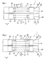
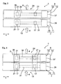
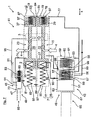
- a filter device 1 for an internal combustion engine in a first mode of operation is shown schematically.
- the filter device 1 is part of an oil circuit, by means of which the internal combustion engine is lubricated and cooled.
- Fig. 1 is no filter on the filter device 1 set while in Fig. 2 several, here two exemplary, schematically indicated filter 2, 3, are set to the filter device 1.
- filters 2, 3, for example particles from an oil stream 4 of the oil circuit are filtered.
- the filter device 1 here comprises by way of example a first cylinder-piston unit 7 and a second cylinder-piston unit 9.
- a cylinder 11 of the cylinder-piston unit 7 has In this case, a circumferentially arranged inlet recess 13, via which the oil flow 4 to be filtered into a cavity 15 (FIG. Fig. 5 ) of the cylinder 11 occurs.
- the cylinder 11 also has two circumferentially arranged, in cylinder-axial direction x spaced outlet recesses 17 through which the oil flow 4 can escape from the cavity 15 of the cylinder 11.
- a filter 2, 3 is fixed to the cylinder 11 such that the oil flow 4 can flow from the cavity 15 of the cylinder 11 into the filters 2, 3.
- a cylinder 19 of the second cylinder-piston unit 9 has two circumferentially arranged, in the cylinder-axial direction x spaced entry recesses 21.
- Each of the filters 2, 3 is fixed in the region of these inlet recesses 21 to the cylinder 19 such that the oil flow 4 from the filters 3 via the inlet recesses 21 into a cavity 23 (FIG. Fig. 5 ) of the cylinder 19 can flow.
- the first cylinder-piston unit 7 is thus here, viewed in the oil flow direction, arranged upstream of the two filters 2, 3 of the filter device 1.
- the second cylinder-piston unit 9, as seen in the oil flow direction, downstream of the two filters 2, 3 is arranged.
- a piston element 25 of the first cylinder-piston unit 7 here by way of example has two pistons 27, 29 spaced apart from one another in the cylinder axial direction x, which are connected to one another by means of a connecting element, here by way of example a rod 31.
- a piston element 33 of the second cylinder-piston unit 9 here likewise has two pistons 35, 37 which are spaced apart from one another in the cylinder axial direction x and which are likewise rigidly connected to one another here by means of a rod 39.
- the inlet recesses 21 of the cylinder 19 can be fluidically closed.
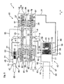
- the piston elements 25, 33 In the in the Fig. 1 and 2 shown operation of the filter device 1, the piston elements 25, 33, however, arranged such that both the outlet recesses 17 and the inlet recesses 21 are not closed by the piston elements 25, 33, so that the oil flow through both filters 2, 3 of the Filter device 1 can flow. Therefore, the in the Fig. 1 and 2 shown operation of the filter device 1 also referred to as a two-filter operation. This two-filter operation is usually used during operation of the filter device 1.
- the filter device 1 can also be placed in the so-called single-filter operation, in which the filter 2, 3 to be changed is fluidically decoupled from the oil flow 4.
- the filter 2 is decoupled from the oil flow 4.
- the piston elements 25, 33 are arranged in such a way that the pistons 27, 35 close the recesses 17, 21 assigned to the filter 2 to be changed. In this way, the supply of the oil flow 4 to the filter 2 and the discharge of the oil flow 4 is blocked from the filter 2, while the supply of the oil flow 4 to the filter 3 and the discharge of the oil flow 4 is released from the filter 3.
- the filter 3 can be decoupled from the oil flow 4, if this filter 3 must be changed.
- the piston elements 25, 33 are then arranged such that the pistons 29, 37 close the recesses 17, 21 associated with the filter 3 to be changed.
- the displacement of the piston elements 25, 33 is by means of a in adjusting device 41 (FIG. Fig. 5 ) of the filter device 1 is controlled.
- each piston 53 also has a recess 59 in which an energy store, here for example a spring element 60, is likewise arranged.
- the spring element 60 is in abutment with the rear wall 61 of the cylinder 47 and presses the piston member 49 in the cylinder-axial direction x away from the wall 61 toward a, seen in the cylinder-axial direction x, front wall 63 of the cylinder 47. Further the piston member 49 in the in Fig.
- a cavity 69 of the valve device 43 is fluidly connected by means of a connecting line 71 to a region 72 of the cavity 15 arranged between the piston 27, 29.
- a cavity 73 of the valve device 45 is fluidly connected by means of a connecting line 74 with a region 75 of the cavity 23 arranged between the pistons 35, 37.
- the cavity 69 of the valve means 43 by means of a connecting line 77 is also fluidically connected with a between the piston 29 and a, seen in the cylinder axial direction x, the rear wall 78 of the cylinder 11 arranged portion 79 of the cavity 15.
- the cavity 74 of the valve device 46 is fluidly connected by means of a connecting line 81 with a between the piston 35 and a, seen in the cylinder axial direction x, the front wall 82 of the cylinder 19 arranged portion 83 of the cavity 23.
- the region 79 of the cavity 15 by means of a connecting line 85 is also fluidically connected with a between the piston 37 and, seen in the cylinder axial direction x, the rear wall 84 of the cylinder 19 arranged portion 87 of the cavity 23.
- the region 83 of the cavity 23 is also fluidly connected by means of a connecting line 88 with a between the piston 27 and a, seen in the cylinder axial direction x, front wall 90 of the cylinder 11 disposed portion 92 of the cavity 15.
- a drain line 89 is connected to the cylinder 47 of the valve device 43, by means of which oil can be discharged from the cavity 69 of the valve device 43 and fed to an oil reservoir, for example an oil pan.
- a drain line 91 is connected to the cylinder 47 of the valve means 45, by means of which the oil can be discharged from the cavity 73 of the valve means 45 and fed to the oil reservoir.
- the cavity 69 of the valve device 43 is also fluidically connected to the filter 2 by means of a discharge line 93, so that oil can be released from the filter 2 by means of the discharge line 93 and fed to the cavity 69 of the valve device 43.
- the cavity 74 of the valve device 45 is fluidly connected to the filter 3 by means of a discharge line 95, so that oil can be drained from the filter 3 by means of the discharge line 95 and fed to the cavity 74 of the valve device 45.
- the pistons 51 of the piston elements 49 block the oil flow through the discharge lines 89, 91, 93 and 95.
- the areas 72, 79 and 92 of the cavity 15 and the areas 75, 83 and 87 of the cavity 23 thus have here an identical oil pressure.
- the piston elements 25, 33 in the required for the two-filter operation, in Fig. 5 shown when the areas 72, 79 and 92 of the cavity 15 and the areas 75, 83 and 87 of the cavity 23 have an identical oil pressure.
- the spring elements 97 and the connecting lines 85, 88 ensure that the piston elements 25, 33 always perform a substantially identical or synchronous lifting movement. Due to this identical or synchronous movement of the piston elements 25, 33 is the Filter device 1 is designed here such that at least one filter 2, 3 is not always decoupled from the oil flow 4 and thus always at least one filter 2, 3 can be flowed through by the oil flow 4.
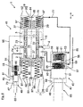
- Fig. 6 was the rod member 65, seen in the piston-axial direction x, moved forward.
- the piston element 49 has also been displaced forward by means of the spring element 60, viewed in the cylinder-axial direction x, until the piston 53 is in contact with stop elements 99 of the valve device 43.
- the piston 51 also blocks the flow of oil through the discharge line 93.
- the piston 53 blocks the flow of oil through the connecting line 71. The oil flow through the connecting line 77 and through the discharge line 89 through the piston member 49 of the valve device 43rd but released. Is like in Fig.
- Fig. 7 are the piston elements 25, 33 of the cylinder-piston units 7, 9 in abutment with the rear walls 78, 84, so that the filter device 1 is in the single-filter operation for changing the filter 2.
- the rod member 65 seen in the cylinder-axial direction x, moved even further to the front, so that the rod member 65 is now outside of the cylinder 47.
- the piston 51 is displaced further forward by means of the spring element 57, viewed in the cylinder-axial direction x, until the piston 51 is in contact with the front wall 63 of the cylinder 47 of the valve device 43.
- the piston 53 further blocks the oil flow through the connecting line 71.
- the oil flow through the connecting line 77, through the discharge line 89 and through the discharge line 93 is however released by the piston element 49 of the valve device 43.
- the residual oil in the filter 2 is discharged from the filter 2 via the discharge lines 89, 93.
- the filter 2 can then be changed and finally the filter device 1 by displacement of the piston member 49 in the first setting position according to Fig. 5 be put back into the two-filter operation.
- the change of the filter 3 is analogous to the change of the filter 2 by actuation of the valve device 45th
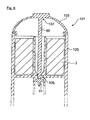
- Fig. 8 is shown as an example of two filter containers 101 of the filter device 1. In each filter container 101 while one of the filters 2, 3 is used. At the in Fig. 8 shown Filter container 101 is used here as an example of the filter 2 in the filter container 101.
- the filter container 101 has a lid 103, which can be releasably fixed by means of a screw connection as a fixing device to a receptacle 105 of the filter container 101.
- the rod element 65 with an end portion 107 here by way of example of the same material and in one piece, set.
- the rod member 65 also with its other end portion 109 so in abutment with the piston 51 (FIGS. Fig. 5 ), that the piston element 49 ( Fig. 5 ) is in its first position.
- the screw connection between the cover 103 and the receptacle 105 is released.
- the rod element 65 displaces in such a way that the piston element 49 (FIG. Fig. 5 ) in the already explained manner first occupies the second parking position and finally the third parking position.
- the lid 103 can be removed together with the rod member 65 from the receptacle 105 and the filter 2 are replaced. If the cover 103 is screwed back to the receptacle 105, and the piston member 49 ( Fig. 5 ) moved again from the third to the first position.
- the filter container 101 is thus ensured that the filter device 1 is always in the two-filter operation when the two filter containers 101 are closed. If a filter container 101 is opened for changing one of the filters 2, 3, the filter device 1 is then put into the single-filter mode.
- the screw connection between the cover 103 and the receptacle 105 is preferably formed by means of a fine thread in order to ensure a controlled and functionally reliable displacement of the piston element 49 during opening and closing of the filter container 101.
Landscapes
- Chemical & Material Sciences (AREA)
- Chemical Kinetics & Catalysis (AREA)
- Engineering & Computer Science (AREA)
- Mechanical Engineering (AREA)
- General Engineering & Computer Science (AREA)
- Lubrication Details And Ventilation Of Internal Combustion Engines (AREA)
- Fluid-Pressure Circuits (AREA)
Applications Claiming Priority (1)
| Application Number | Priority Date | Filing Date | Title |
|---|---|---|---|
| DE102014012473.8A DE102014012473A1 (de) | 2014-08-21 | 2014-08-21 | Verfahren und Vorrichtung zum Wechseln eines Filters, insbesondere eines Ölfilters für eine Brennkraftmaschine |
Publications (3)
| Publication Number | Publication Date |
|---|---|
| EP2987543A2 true EP2987543A2 (fr) | 2016-02-24 |
| EP2987543A3 EP2987543A3 (fr) | 2016-04-13 |
| EP2987543B1 EP2987543B1 (fr) | 2019-11-13 |
Family
ID=53442423
Family Applications (1)
| Application Number | Title | Priority Date | Filing Date |
|---|---|---|---|
| EP15001575.8A Active EP2987543B1 (fr) | 2014-08-21 | 2015-05-23 | Procede et dispositif de changement d'un filtre, en particulier d'un filtre a huile pour un moteur a combustion interne |
Country Status (2)
| Country | Link |
|---|---|
| EP (1) | EP2987543B1 (fr) |
| DE (1) | DE102014012473A1 (fr) |
Citations (1)
| Publication number | Priority date | Publication date | Assignee | Title |
|---|---|---|---|---|
| EP2476870A1 (fr) | 2011-01-15 | 2012-07-18 | MAN Truck & Bus AG | Dispositif d'alimentation en huile pour un moteur à combustion interne, notamment pour le carter d'un moteur à combustion interne |
Family Cites Families (5)
| Publication number | Priority date | Publication date | Assignee | Title |
|---|---|---|---|---|
| CH673618A5 (fr) * | 1987-10-29 | 1990-03-30 | Indupack Ag | |
| DE19637299A1 (de) * | 1996-09-13 | 1998-03-19 | Daimler Benz Ag | Filtersystem insbesondere für das Schmiermittel einer Brennkraftmaschine |
| FI104958B (fi) * | 1998-09-30 | 2000-05-15 | Parker Hannifin Oy | Jatkuvatoiminen suodatusmenetelmä ja -laitteisto |
| DE60030041D1 (de) * | 1999-06-23 | 2006-09-28 | Fleetguard Inc | Filtervorrichtung für Brennkraftmaschinen |
| US6290208B1 (en) * | 1999-11-03 | 2001-09-18 | Fleetguard, Inc. | Valve seal, including for duplex head |
-
2014
- 2014-08-21 DE DE102014012473.8A patent/DE102014012473A1/de not_active Withdrawn
-
2015
- 2015-05-23 EP EP15001575.8A patent/EP2987543B1/fr active Active
Patent Citations (1)
| Publication number | Priority date | Publication date | Assignee | Title |
|---|---|---|---|---|
| EP2476870A1 (fr) | 2011-01-15 | 2012-07-18 | MAN Truck & Bus AG | Dispositif d'alimentation en huile pour un moteur à combustion interne, notamment pour le carter d'un moteur à combustion interne |
Also Published As
| Publication number | Publication date |
|---|---|
| EP2987543A3 (fr) | 2016-04-13 |
| EP2987543B1 (fr) | 2019-11-13 |
| DE102014012473A1 (de) | 2016-02-25 |
Similar Documents
| Publication | Publication Date | Title |
|---|---|---|
| EP3265202B1 (fr) | Dispositif de filtration de fluides | |
| DE102012006563B3 (de) | Vorrichtung zum Filtrieren eines Fluids | |
| EP2435713B1 (fr) | Procédé destiné à enlever des impuretés d'un régulateur numérique de pression hydraulique d'un système hydraulique | |
| EP0554237B1 (fr) | Appareil de filtration pour fluides contaminés et procédé pour sa mise en oeuvre | |
| DE3941831C1 (fr) | ||
| DE102014016634A1 (de) | Filtriervorrichtung zum Filtrieren eines Fluids | |
| WO2005085653A1 (fr) | Unite de securite | |
| DE10056557A1 (de) | Rückspülvorsatzgerät für eine Filtereinrichtung | |
| DE102016120975A1 (de) | Längenverstellbare Pleuelstange mit einer Zylinder-Kolben-Einheit mit Ölfilter | |
| EP3424618A1 (fr) | Fermeture coulissante pour un récipient contenant un métal en fusion | |
| DE102007009419A1 (de) | Filtereinrichtung für flüssige Medien | |
| DE202010017247U1 (de) | Vorrichtung zum Filtrieren eines Fluids | |
| DE2845448A1 (de) | Hydraulische antriebsvorrichtung fuer eine spritzgiessmaschine | |
| DE102013002729A1 (de) | Druckluft-Wartungsgerät zum Filtern von Druckluft sowie Verfahren zum Wechseln einer Filterpatrone | |
| EP2987543B1 (fr) | Procede et dispositif de changement d'un filtre, en particulier d'un filtre a huile pour un moteur a combustion interne | |
| DE2444012B1 (de) | Vorrichtung zum Verarbeiten, insbesondere zum Extrudieren, von schmelzflüssigen Kunststoffen | |
| EP0622139A2 (fr) | Système d'entraînement pour un obtinateur du tron de coulée d'un conteneur métallingique | |
| EP2059378B1 (fr) | Dispositif de filtration de matière synthétique thermoplastique fondue | |
| DE102005029822A1 (de) | Hydraulische Umformanlage | |
| DE2130501A1 (de) | Vorrichtung zum Auswechseln von Sieben | |
| DE102014222326B4 (de) | Hydraulikanordnung | |
| DE102022124308A1 (de) | Filtriervorrichtung zum Filtrieren eines Fluids sowie betreffendes Entlüftungs- und Rückspülverfahren | |
| EP0976520B1 (fr) | Piston d'injection pour matière plastique fondue | |
| DE102010025163A1 (de) | Vorrichtung zum Filtrieren eines Fluids | |
| DE29917562U1 (de) | Fluidfilter mit einem montierbarem, zentralen Bauteil |
Legal Events
| Date | Code | Title | Description |
|---|---|---|---|
| PUAI | Public reference made under article 153(3) epc to a published international application that has entered the european phase |
Free format text: ORIGINAL CODE: 0009012 |
|
| AK | Designated contracting states |
Kind code of ref document: A2 Designated state(s): AL AT BE BG CH CY CZ DE DK EE ES FI FR GB GR HR HU IE IS IT LI LT LU LV MC MK MT NL NO PL PT RO RS SE SI SK SM TR |
|
| AX | Request for extension of the european patent |
Extension state: BA ME |
|
| PUAL | Search report despatched |
Free format text: ORIGINAL CODE: 0009013 |
|
| AK | Designated contracting states |
Kind code of ref document: A3 Designated state(s): AL AT BE BG CH CY CZ DE DK EE ES FI FR GB GR HR HU IE IS IT LI LT LU LV MC MK MT NL NO PL PT RO RS SE SI SK SM TR |
|
| AX | Request for extension of the european patent |
Extension state: BA ME |
|
| RIC1 | Information provided on ipc code assigned before grant |
Ipc: F01M 1/10 20060101ALI20160310BHEP Ipc: F02M 37/00 20060101ALI20160310BHEP Ipc: B01D 35/157 20060101ALI20160310BHEP Ipc: B01D 35/12 20060101AFI20160310BHEP |
|
| 17P | Request for examination filed |
Effective date: 20161013 |
|
| GRAP | Despatch of communication of intention to grant a patent |
Free format text: ORIGINAL CODE: EPIDOSNIGR1 |
|
| STAA | Information on the status of an ep patent application or granted ep patent |
Free format text: STATUS: GRANT OF PATENT IS INTENDED |
|
| INTG | Intention to grant announced |
Effective date: 20181221 |
|
| GRAJ | Information related to disapproval of communication of intention to grant by the applicant or resumption of examination proceedings by the epo deleted |
Free format text: ORIGINAL CODE: EPIDOSDIGR1 |
|
| STAA | Information on the status of an ep patent application or granted ep patent |
Free format text: STATUS: REQUEST FOR EXAMINATION WAS MADE |
|
| INTC | Intention to grant announced (deleted) | ||
| GRAP | Despatch of communication of intention to grant a patent |
Free format text: ORIGINAL CODE: EPIDOSNIGR1 |
|
| STAA | Information on the status of an ep patent application or granted ep patent |
Free format text: STATUS: GRANT OF PATENT IS INTENDED |
|
| INTG | Intention to grant announced |
Effective date: 20190531 |
|
| RAP1 | Party data changed (applicant data changed or rights of an application transferred) |
Owner name: MAN TRUCK & BUS SE |
|
| GRAS | Grant fee paid |
Free format text: ORIGINAL CODE: EPIDOSNIGR3 |
|
| GRAA | (expected) grant |
Free format text: ORIGINAL CODE: 0009210 |
|
| STAA | Information on the status of an ep patent application or granted ep patent |
Free format text: STATUS: THE PATENT HAS BEEN GRANTED |
|
| AK | Designated contracting states |
Kind code of ref document: B1 Designated state(s): AL AT BE BG CH CY CZ DE DK EE ES FI FR GB GR HR HU IE IS IT LI LT LU LV MC MK MT NL NO PL PT RO RS SE SI SK SM TR |
|
| REG | Reference to a national code |
Ref country code: CH Ref legal event code: EP Ref country code: AT Ref legal event code: REF Ref document number: 1201077 Country of ref document: AT Kind code of ref document: T Effective date: 20191115 |
|
| REG | Reference to a national code |
Ref country code: DE Ref legal event code: R096 Ref document number: 502015010897 Country of ref document: DE |
|
| REG | Reference to a national code |
Ref country code: IE Ref legal event code: FG4D Free format text: LANGUAGE OF EP DOCUMENT: GERMAN |
|
| REG | Reference to a national code |
Ref country code: NL Ref legal event code: FP |
|
| REG | Reference to a national code |
Ref country code: SE Ref legal event code: TRGR |
|
| REG | Reference to a national code |
Ref country code: LT Ref legal event code: MG4D |
|
| PG25 | Lapsed in a contracting state [announced via postgrant information from national office to epo] |
Ref country code: LV Free format text: LAPSE BECAUSE OF FAILURE TO SUBMIT A TRANSLATION OF THE DESCRIPTION OR TO PAY THE FEE WITHIN THE PRESCRIBED TIME-LIMIT Effective date: 20191113 Ref country code: LT Free format text: LAPSE BECAUSE OF FAILURE TO SUBMIT A TRANSLATION OF THE DESCRIPTION OR TO PAY THE FEE WITHIN THE PRESCRIBED TIME-LIMIT Effective date: 20191113 Ref country code: GR Free format text: LAPSE BECAUSE OF FAILURE TO SUBMIT A TRANSLATION OF THE DESCRIPTION OR TO PAY THE FEE WITHIN THE PRESCRIBED TIME-LIMIT Effective date: 20200214 Ref country code: NO Free format text: LAPSE BECAUSE OF FAILURE TO SUBMIT A TRANSLATION OF THE DESCRIPTION OR TO PAY THE FEE WITHIN THE PRESCRIBED TIME-LIMIT Effective date: 20200213 Ref country code: PL Free format text: LAPSE BECAUSE OF FAILURE TO SUBMIT A TRANSLATION OF THE DESCRIPTION OR TO PAY THE FEE WITHIN THE PRESCRIBED TIME-LIMIT Effective date: 20191113 Ref country code: PT Free format text: LAPSE BECAUSE OF FAILURE TO SUBMIT A TRANSLATION OF THE DESCRIPTION OR TO PAY THE FEE WITHIN THE PRESCRIBED TIME-LIMIT Effective date: 20200313 Ref country code: FI Free format text: LAPSE BECAUSE OF FAILURE TO SUBMIT A TRANSLATION OF THE DESCRIPTION OR TO PAY THE FEE WITHIN THE PRESCRIBED TIME-LIMIT Effective date: 20191113 Ref country code: BG Free format text: LAPSE BECAUSE OF FAILURE TO SUBMIT A TRANSLATION OF THE DESCRIPTION OR TO PAY THE FEE WITHIN THE PRESCRIBED TIME-LIMIT Effective date: 20200213 |
|
| PG25 | Lapsed in a contracting state [announced via postgrant information from national office to epo] |
Ref country code: RS Free format text: LAPSE BECAUSE OF FAILURE TO SUBMIT A TRANSLATION OF THE DESCRIPTION OR TO PAY THE FEE WITHIN THE PRESCRIBED TIME-LIMIT Effective date: 20191113 Ref country code: HR Free format text: LAPSE BECAUSE OF FAILURE TO SUBMIT A TRANSLATION OF THE DESCRIPTION OR TO PAY THE FEE WITHIN THE PRESCRIBED TIME-LIMIT Effective date: 20191113 Ref country code: IS Free format text: LAPSE BECAUSE OF FAILURE TO SUBMIT A TRANSLATION OF THE DESCRIPTION OR TO PAY THE FEE WITHIN THE PRESCRIBED TIME-LIMIT Effective date: 20200313 |
|
| PG25 | Lapsed in a contracting state [announced via postgrant information from national office to epo] |
Ref country code: AL Free format text: LAPSE BECAUSE OF FAILURE TO SUBMIT A TRANSLATION OF THE DESCRIPTION OR TO PAY THE FEE WITHIN THE PRESCRIBED TIME-LIMIT Effective date: 20191113 |
|
| PG25 | Lapsed in a contracting state [announced via postgrant information from national office to epo] |
Ref country code: CZ Free format text: LAPSE BECAUSE OF FAILURE TO SUBMIT A TRANSLATION OF THE DESCRIPTION OR TO PAY THE FEE WITHIN THE PRESCRIBED TIME-LIMIT Effective date: 20191113 Ref country code: RO Free format text: LAPSE BECAUSE OF FAILURE TO SUBMIT A TRANSLATION OF THE DESCRIPTION OR TO PAY THE FEE WITHIN THE PRESCRIBED TIME-LIMIT Effective date: 20191113 Ref country code: EE Free format text: LAPSE BECAUSE OF FAILURE TO SUBMIT A TRANSLATION OF THE DESCRIPTION OR TO PAY THE FEE WITHIN THE PRESCRIBED TIME-LIMIT Effective date: 20191113 Ref country code: DK Free format text: LAPSE BECAUSE OF FAILURE TO SUBMIT A TRANSLATION OF THE DESCRIPTION OR TO PAY THE FEE WITHIN THE PRESCRIBED TIME-LIMIT Effective date: 20191113 Ref country code: ES Free format text: LAPSE BECAUSE OF FAILURE TO SUBMIT A TRANSLATION OF THE DESCRIPTION OR TO PAY THE FEE WITHIN THE PRESCRIBED TIME-LIMIT Effective date: 20191113 |
|
| REG | Reference to a national code |
Ref country code: DE Ref legal event code: R097 Ref document number: 502015010897 Country of ref document: DE |
|
| PG25 | Lapsed in a contracting state [announced via postgrant information from national office to epo] |
Ref country code: SK Free format text: LAPSE BECAUSE OF FAILURE TO SUBMIT A TRANSLATION OF THE DESCRIPTION OR TO PAY THE FEE WITHIN THE PRESCRIBED TIME-LIMIT Effective date: 20191113 Ref country code: SM Free format text: LAPSE BECAUSE OF FAILURE TO SUBMIT A TRANSLATION OF THE DESCRIPTION OR TO PAY THE FEE WITHIN THE PRESCRIBED TIME-LIMIT Effective date: 20191113 |
|
| PLBE | No opposition filed within time limit |
Free format text: ORIGINAL CODE: 0009261 |
|
| STAA | Information on the status of an ep patent application or granted ep patent |
Free format text: STATUS: NO OPPOSITION FILED WITHIN TIME LIMIT |
|
| 26N | No opposition filed |
Effective date: 20200814 |
|
| PG25 | Lapsed in a contracting state [announced via postgrant information from national office to epo] |
Ref country code: SI Free format text: LAPSE BECAUSE OF FAILURE TO SUBMIT A TRANSLATION OF THE DESCRIPTION OR TO PAY THE FEE WITHIN THE PRESCRIBED TIME-LIMIT Effective date: 20191113 |
|
| PG25 | Lapsed in a contracting state [announced via postgrant information from national office to epo] |
Ref country code: LI Free format text: LAPSE BECAUSE OF NON-PAYMENT OF DUE FEES Effective date: 20200531 Ref country code: CH Free format text: LAPSE BECAUSE OF NON-PAYMENT OF DUE FEES Effective date: 20200531 Ref country code: MC Free format text: LAPSE BECAUSE OF FAILURE TO SUBMIT A TRANSLATION OF THE DESCRIPTION OR TO PAY THE FEE WITHIN THE PRESCRIBED TIME-LIMIT Effective date: 20191113 |
|
| REG | Reference to a national code |
Ref country code: BE Ref legal event code: MM Effective date: 20200531 |
|
| GBPC | Gb: european patent ceased through non-payment of renewal fee |
Effective date: 20200523 |
|
| PG25 | Lapsed in a contracting state [announced via postgrant information from national office to epo] |
Ref country code: LU Free format text: LAPSE BECAUSE OF NON-PAYMENT OF DUE FEES Effective date: 20200523 |
|
| PG25 | Lapsed in a contracting state [announced via postgrant information from national office to epo] |
Ref country code: IE Free format text: LAPSE BECAUSE OF NON-PAYMENT OF DUE FEES Effective date: 20200523 Ref country code: GB Free format text: LAPSE BECAUSE OF NON-PAYMENT OF DUE FEES Effective date: 20200523 |
|
| PG25 | Lapsed in a contracting state [announced via postgrant information from national office to epo] |
Ref country code: BE Free format text: LAPSE BECAUSE OF NON-PAYMENT OF DUE FEES Effective date: 20200531 |
|
| REG | Reference to a national code |
Ref country code: AT Ref legal event code: MM01 Ref document number: 1201077 Country of ref document: AT Kind code of ref document: T Effective date: 20200523 |
|
| PG25 | Lapsed in a contracting state [announced via postgrant information from national office to epo] |
Ref country code: AT Free format text: LAPSE BECAUSE OF NON-PAYMENT OF DUE FEES Effective date: 20200523 |
|
| PG25 | Lapsed in a contracting state [announced via postgrant information from national office to epo] |
Ref country code: TR Free format text: LAPSE BECAUSE OF FAILURE TO SUBMIT A TRANSLATION OF THE DESCRIPTION OR TO PAY THE FEE WITHIN THE PRESCRIBED TIME-LIMIT Effective date: 20191113 Ref country code: MT Free format text: LAPSE BECAUSE OF FAILURE TO SUBMIT A TRANSLATION OF THE DESCRIPTION OR TO PAY THE FEE WITHIN THE PRESCRIBED TIME-LIMIT Effective date: 20191113 Ref country code: CY Free format text: LAPSE BECAUSE OF FAILURE TO SUBMIT A TRANSLATION OF THE DESCRIPTION OR TO PAY THE FEE WITHIN THE PRESCRIBED TIME-LIMIT Effective date: 20191113 |
|
| PG25 | Lapsed in a contracting state [announced via postgrant information from national office to epo] |
Ref country code: MK Free format text: LAPSE BECAUSE OF FAILURE TO SUBMIT A TRANSLATION OF THE DESCRIPTION OR TO PAY THE FEE WITHIN THE PRESCRIBED TIME-LIMIT Effective date: 20191113 |
|
| PGFP | Annual fee paid to national office [announced via postgrant information from national office to epo] |
Ref country code: NL Payment date: 20250526 Year of fee payment: 11 |
|
| PGFP | Annual fee paid to national office [announced via postgrant information from national office to epo] |
Ref country code: DE Payment date: 20250528 Year of fee payment: 11 |
|
| PGFP | Annual fee paid to national office [announced via postgrant information from national office to epo] |
Ref country code: IT Payment date: 20250522 Year of fee payment: 11 |
|
| PGFP | Annual fee paid to national office [announced via postgrant information from national office to epo] |
Ref country code: FR Payment date: 20250526 Year of fee payment: 11 |
|
| PGFP | Annual fee paid to national office [announced via postgrant information from national office to epo] |
Ref country code: SE Payment date: 20250526 Year of fee payment: 11 |