EP2987624B1 - Couverture chauffante - Google Patents
Couverture chauffante Download PDFInfo
- Publication number
- EP2987624B1 EP2987624B1 EP14181761.9A EP14181761A EP2987624B1 EP 2987624 B1 EP2987624 B1 EP 2987624B1 EP 14181761 A EP14181761 A EP 14181761A EP 2987624 B1 EP2987624 B1 EP 2987624B1
- Authority
- EP
- European Patent Office
- Prior art keywords
- heating
- heating blanket
- sleeve
- pipe assembly
- sheet
- Prior art date
- Legal status (The legal status is an assumption and is not a legal conclusion. Google has not performed a legal analysis and makes no representation as to the accuracy of the status listed.)
- Not-in-force
Links
- 238000010438 heat treatment Methods 0.000 title claims description 150
- 238000009413 insulation Methods 0.000 claims description 34
- 238000000034 method Methods 0.000 claims description 26
- 239000000463 material Substances 0.000 claims description 20
- 239000000853 adhesive Substances 0.000 claims description 8
- 230000001070 adhesive effect Effects 0.000 claims description 8
- 229920001903 high density polyethylene Polymers 0.000 claims description 7
- 239000004700 high-density polyethylene Substances 0.000 claims description 7
- 239000013521 mastic Substances 0.000 claims description 6
- 229920001296 polysiloxane Polymers 0.000 claims description 6
- 239000004743 Polypropylene Substances 0.000 claims description 4
- 229920001684 low density polyethylene Polymers 0.000 claims description 4
- 239000004702 low-density polyethylene Substances 0.000 claims description 4
- 229920001155 polypropylene Polymers 0.000 claims description 4
- -1 polypropylene Polymers 0.000 claims description 3
- 239000004831 Hot glue Substances 0.000 claims description 2
- 239000010410 layer Substances 0.000 description 27
- 230000008569 process Effects 0.000 description 9
- 239000011248 coating agent Substances 0.000 description 8
- 238000000576 coating method Methods 0.000 description 8
- 239000012943 hotmelt Substances 0.000 description 8
- 238000013021 overheating Methods 0.000 description 4
- 239000004593 Epoxy Substances 0.000 description 3
- 230000008901 benefit Effects 0.000 description 3
- 230000006835 compression Effects 0.000 description 3
- 238000007906 compression Methods 0.000 description 3
- 239000000835 fiber Substances 0.000 description 3
- 230000000712 assembly Effects 0.000 description 2
- 238000000429 assembly Methods 0.000 description 2
- 230000004888 barrier function Effects 0.000 description 2
- 238000005260 corrosion Methods 0.000 description 2
- 230000007797 corrosion Effects 0.000 description 2
- 239000002360 explosive Substances 0.000 description 2
- 239000006260 foam Substances 0.000 description 2
- 239000006261 foam material Substances 0.000 description 2
- 239000003365 glass fiber Substances 0.000 description 2
- 230000001681 protective effect Effects 0.000 description 2
- 229920000049 Carbon (fiber) Polymers 0.000 description 1
- 229920000271 Kevlar® Polymers 0.000 description 1
- 229920003235 aromatic polyamide Polymers 0.000 description 1
- 239000004917 carbon fiber Substances 0.000 description 1
- 230000008859 change Effects 0.000 description 1
- 238000002485 combustion reaction Methods 0.000 description 1
- 239000002131 composite material Substances 0.000 description 1
- 230000003628 erosive effect Effects 0.000 description 1
- 239000012530 fluid Substances 0.000 description 1
- 239000007789 gas Substances 0.000 description 1
- 239000011521 glass Substances 0.000 description 1
- 239000012774 insulation material Substances 0.000 description 1
- 239000004761 kevlar Substances 0.000 description 1
- 230000002045 lasting effect Effects 0.000 description 1
- 238000005259 measurement Methods 0.000 description 1
- 238000002844 melting Methods 0.000 description 1
- 230000008018 melting Effects 0.000 description 1
- VNWKTOKETHGBQD-UHFFFAOYSA-N methane Chemical compound C VNWKTOKETHGBQD-UHFFFAOYSA-N 0.000 description 1
- 238000012986 modification Methods 0.000 description 1
- 230000004048 modification Effects 0.000 description 1
- 239000002245 particle Substances 0.000 description 1
- 229920002635 polyurethane Polymers 0.000 description 1
- 239000004814 polyurethane Substances 0.000 description 1
- 239000011241 protective layer Substances 0.000 description 1
- 230000002787 reinforcement Effects 0.000 description 1
- 238000007789 sealing Methods 0.000 description 1
- 229920002994 synthetic fiber Polymers 0.000 description 1
- 239000012209 synthetic fiber Substances 0.000 description 1
- 238000012360 testing method Methods 0.000 description 1
Images


Classifications
-
- B—PERFORMING OPERATIONS; TRANSPORTING
- B29—WORKING OF PLASTICS; WORKING OF SUBSTANCES IN A PLASTIC STATE IN GENERAL
- B29C—SHAPING OR JOINING OF PLASTICS; SHAPING OF MATERIAL IN A PLASTIC STATE, NOT OTHERWISE PROVIDED FOR; AFTER-TREATMENT OF THE SHAPED PRODUCTS, e.g. REPAIRING
- B29C63/00—Lining or sheathing, i.e. applying preformed layers or sheathings of plastics; Apparatus therefor
- B29C63/38—Lining or sheathing, i.e. applying preformed layers or sheathings of plastics; Apparatus therefor by liberation of internal stresses
- B29C63/42—Lining or sheathing, i.e. applying preformed layers or sheathings of plastics; Apparatus therefor by liberation of internal stresses using tubular layers or sheathings
-
- B—PERFORMING OPERATIONS; TRANSPORTING
- B29—WORKING OF PLASTICS; WORKING OF SUBSTANCES IN A PLASTIC STATE IN GENERAL
- B29C—SHAPING OR JOINING OF PLASTICS; SHAPING OF MATERIAL IN A PLASTIC STATE, NOT OTHERWISE PROVIDED FOR; AFTER-TREATMENT OF THE SHAPED PRODUCTS, e.g. REPAIRING
- B29C65/00—Joining or sealing of preformed parts, e.g. welding of plastics materials; Apparatus therefor
- B29C65/02—Joining or sealing of preformed parts, e.g. welding of plastics materials; Apparatus therefor by heating, with or without pressure
- B29C65/18—Joining or sealing of preformed parts, e.g. welding of plastics materials; Apparatus therefor by heating, with or without pressure using heated tools
- B29C65/22—Heated wire resistive ribbon, resistive band or resistive strip
- B29C65/221—Heated wire resistive ribbon, resistive band or resistive strip characterised by the type of heated wire, resistive ribbon, band or strip
- B29C65/222—Heated wire resistive ribbon, resistive band or resistive strip characterised by the type of heated wire, resistive ribbon, band or strip comprising at least a single heated wire
- B29C65/223—Heated wire resistive ribbon, resistive band or resistive strip characterised by the type of heated wire, resistive ribbon, band or strip comprising at least a single heated wire comprising several heated wires
-
- B—PERFORMING OPERATIONS; TRANSPORTING
- B29—WORKING OF PLASTICS; WORKING OF SUBSTANCES IN A PLASTIC STATE IN GENERAL
- B29C—SHAPING OR JOINING OF PLASTICS; SHAPING OF MATERIAL IN A PLASTIC STATE, NOT OTHERWISE PROVIDED FOR; AFTER-TREATMENT OF THE SHAPED PRODUCTS, e.g. REPAIRING
- B29C65/00—Joining or sealing of preformed parts, e.g. welding of plastics materials; Apparatus therefor
- B29C65/66—Joining or sealing of preformed parts, e.g. welding of plastics materials; Apparatus therefor by liberation of internal stresses, e.g. shrinking of one of the parts to be joined
- B29C65/68—Joining or sealing of preformed parts, e.g. welding of plastics materials; Apparatus therefor by liberation of internal stresses, e.g. shrinking of one of the parts to be joined using auxiliary shrinkable elements
-
- B—PERFORMING OPERATIONS; TRANSPORTING
- B29—WORKING OF PLASTICS; WORKING OF SUBSTANCES IN A PLASTIC STATE IN GENERAL
- B29C—SHAPING OR JOINING OF PLASTICS; SHAPING OF MATERIAL IN A PLASTIC STATE, NOT OTHERWISE PROVIDED FOR; AFTER-TREATMENT OF THE SHAPED PRODUCTS, e.g. REPAIRING
- B29C66/00—General aspects of processes or apparatus for joining preformed parts
- B29C66/01—General aspects dealing with the joint area or with the area to be joined
- B29C66/05—Particular design of joint configurations
- B29C66/10—Particular design of joint configurations particular design of the joint cross-sections
- B29C66/11—Joint cross-sections comprising a single joint-segment, i.e. one of the parts to be joined comprising a single joint-segment in the joint cross-section
- B29C66/112—Single lapped joints
- B29C66/1122—Single lap to lap joints, i.e. overlap joints
-
- B—PERFORMING OPERATIONS; TRANSPORTING
- B29—WORKING OF PLASTICS; WORKING OF SUBSTANCES IN A PLASTIC STATE IN GENERAL
- B29C—SHAPING OR JOINING OF PLASTICS; SHAPING OF MATERIAL IN A PLASTIC STATE, NOT OTHERWISE PROVIDED FOR; AFTER-TREATMENT OF THE SHAPED PRODUCTS, e.g. REPAIRING
- B29C66/00—General aspects of processes or apparatus for joining preformed parts
- B29C66/01—General aspects dealing with the joint area or with the area to be joined
- B29C66/345—Progressively making the joint, e.g. starting from the middle
-
- B—PERFORMING OPERATIONS; TRANSPORTING
- B29—WORKING OF PLASTICS; WORKING OF SUBSTANCES IN A PLASTIC STATE IN GENERAL
- B29C—SHAPING OR JOINING OF PLASTICS; SHAPING OF MATERIAL IN A PLASTIC STATE, NOT OTHERWISE PROVIDED FOR; AFTER-TREATMENT OF THE SHAPED PRODUCTS, e.g. REPAIRING
- B29C66/00—General aspects of processes or apparatus for joining preformed parts
- B29C66/50—General aspects of joining tubular articles; General aspects of joining long products, i.e. bars or profiled elements; General aspects of joining single elements to tubular articles, hollow articles or bars; General aspects of joining several hollow-preforms to form hollow or tubular articles
- B29C66/51—Joining tubular articles, profiled elements or bars; Joining single elements to tubular articles, hollow articles or bars; Joining several hollow-preforms to form hollow or tubular articles
- B29C66/53—Joining single elements to tubular articles, hollow articles or bars
- B29C66/532—Joining single elements to the wall of tubular articles, hollow articles or bars
- B29C66/5326—Joining single elements to the wall of tubular articles, hollow articles or bars said single elements being substantially flat
-
- B—PERFORMING OPERATIONS; TRANSPORTING
- B29—WORKING OF PLASTICS; WORKING OF SUBSTANCES IN A PLASTIC STATE IN GENERAL
- B29C—SHAPING OR JOINING OF PLASTICS; SHAPING OF MATERIAL IN A PLASTIC STATE, NOT OTHERWISE PROVIDED FOR; AFTER-TREATMENT OF THE SHAPED PRODUCTS, e.g. REPAIRING
- B29C66/00—General aspects of processes or apparatus for joining preformed parts
- B29C66/70—General aspects of processes or apparatus for joining preformed parts characterised by the composition, physical properties or the structure of the material of the parts to be joined; Joining with non-plastics material
- B29C66/72—General aspects of processes or apparatus for joining preformed parts characterised by the composition, physical properties or the structure of the material of the parts to be joined; Joining with non-plastics material characterised by the structure of the material of the parts to be joined
- B29C66/723—General aspects of processes or apparatus for joining preformed parts characterised by the composition, physical properties or the structure of the material of the parts to be joined; Joining with non-plastics material characterised by the structure of the material of the parts to be joined being multi-layered
-
- B—PERFORMING OPERATIONS; TRANSPORTING
- B29—WORKING OF PLASTICS; WORKING OF SUBSTANCES IN A PLASTIC STATE IN GENERAL
- B29C—SHAPING OR JOINING OF PLASTICS; SHAPING OF MATERIAL IN A PLASTIC STATE, NOT OTHERWISE PROVIDED FOR; AFTER-TREATMENT OF THE SHAPED PRODUCTS, e.g. REPAIRING
- B29C66/00—General aspects of processes or apparatus for joining preformed parts
- B29C66/70—General aspects of processes or apparatus for joining preformed parts characterised by the composition, physical properties or the structure of the material of the parts to be joined; Joining with non-plastics material
- B29C66/74—Joining plastics material to non-plastics material
- B29C66/742—Joining plastics material to non-plastics material to metals or their alloys
-
- B—PERFORMING OPERATIONS; TRANSPORTING
- B29—WORKING OF PLASTICS; WORKING OF SUBSTANCES IN A PLASTIC STATE IN GENERAL
- B29C—SHAPING OR JOINING OF PLASTICS; SHAPING OF MATERIAL IN A PLASTIC STATE, NOT OTHERWISE PROVIDED FOR; AFTER-TREATMENT OF THE SHAPED PRODUCTS, e.g. REPAIRING
- B29C66/00—General aspects of processes or apparatus for joining preformed parts
- B29C66/80—General aspects of machine operations or constructions and parts thereof
- B29C66/81—General aspects of the pressing elements, i.e. the elements applying pressure on the parts to be joined in the area to be joined, e.g. the welding jaws or clamps
- B29C66/814—General aspects of the pressing elements, i.e. the elements applying pressure on the parts to be joined in the area to be joined, e.g. the welding jaws or clamps characterised by the design of the pressing elements, e.g. of the welding jaws or clamps
- B29C66/8145—General aspects of the pressing elements, i.e. the elements applying pressure on the parts to be joined in the area to be joined, e.g. the welding jaws or clamps characterised by the design of the pressing elements, e.g. of the welding jaws or clamps characterised by the constructional aspects of the pressing elements, e.g. of the welding jaws or clamps
- B29C66/81471—General aspects of the pressing elements, i.e. the elements applying pressure on the parts to be joined in the area to be joined, e.g. the welding jaws or clamps characterised by the design of the pressing elements, e.g. of the welding jaws or clamps characterised by the constructional aspects of the pressing elements, e.g. of the welding jaws or clamps being a wrap-around tape or band
-
- B—PERFORMING OPERATIONS; TRANSPORTING
- B29—WORKING OF PLASTICS; WORKING OF SUBSTANCES IN A PLASTIC STATE IN GENERAL
- B29C—SHAPING OR JOINING OF PLASTICS; SHAPING OF MATERIAL IN A PLASTIC STATE, NOT OTHERWISE PROVIDED FOR; AFTER-TREATMENT OF THE SHAPED PRODUCTS, e.g. REPAIRING
- B29C66/00—General aspects of processes or apparatus for joining preformed parts
- B29C66/80—General aspects of machine operations or constructions and parts thereof
- B29C66/81—General aspects of the pressing elements, i.e. the elements applying pressure on the parts to be joined in the area to be joined, e.g. the welding jaws or clamps
- B29C66/818—General aspects of the pressing elements, i.e. the elements applying pressure on the parts to be joined in the area to be joined, e.g. the welding jaws or clamps characterised by the cooling constructional aspects, or by the thermal or electrical insulating or conducting constructional aspects of the welding jaws or of the clamps ; comprising means for compensating for the thermal expansion of the welding jaws or of the clamps
- B29C66/8182—General aspects of the pressing elements, i.e. the elements applying pressure on the parts to be joined in the area to be joined, e.g. the welding jaws or clamps characterised by the cooling constructional aspects, or by the thermal or electrical insulating or conducting constructional aspects of the welding jaws or of the clamps ; comprising means for compensating for the thermal expansion of the welding jaws or of the clamps characterised by the thermal insulating constructional aspects
- B29C66/81821—General aspects of the pressing elements, i.e. the elements applying pressure on the parts to be joined in the area to be joined, e.g. the welding jaws or clamps characterised by the cooling constructional aspects, or by the thermal or electrical insulating or conducting constructional aspects of the welding jaws or of the clamps ; comprising means for compensating for the thermal expansion of the welding jaws or of the clamps characterised by the thermal insulating constructional aspects of the welding jaws
-
- B—PERFORMING OPERATIONS; TRANSPORTING
- B29—WORKING OF PLASTICS; WORKING OF SUBSTANCES IN A PLASTIC STATE IN GENERAL
- B29C—SHAPING OR JOINING OF PLASTICS; SHAPING OF MATERIAL IN A PLASTIC STATE, NOT OTHERWISE PROVIDED FOR; AFTER-TREATMENT OF THE SHAPED PRODUCTS, e.g. REPAIRING
- B29C66/00—General aspects of processes or apparatus for joining preformed parts
- B29C66/90—Measuring or controlling the joining process
- B29C66/91—Measuring or controlling the joining process by measuring or controlling the temperature, the heat or the thermal flux
- B29C66/912—Measuring or controlling the joining process by measuring or controlling the temperature, the heat or the thermal flux by measuring the temperature, the heat or the thermal flux
- B29C66/9121—Measuring or controlling the joining process by measuring or controlling the temperature, the heat or the thermal flux by measuring the temperature, the heat or the thermal flux by measuring the temperature
- B29C66/91211—Measuring or controlling the joining process by measuring or controlling the temperature, the heat or the thermal flux by measuring the temperature, the heat or the thermal flux by measuring the temperature with special temperature measurement means or methods
- B29C66/91212—Measuring or controlling the joining process by measuring or controlling the temperature, the heat or the thermal flux by measuring the temperature, the heat or the thermal flux by measuring the temperature with special temperature measurement means or methods involving measurement means being part of the welding jaws, e.g. integrated in the welding jaws
-
- B—PERFORMING OPERATIONS; TRANSPORTING
- B29—WORKING OF PLASTICS; WORKING OF SUBSTANCES IN A PLASTIC STATE IN GENERAL
- B29C—SHAPING OR JOINING OF PLASTICS; SHAPING OF MATERIAL IN A PLASTIC STATE, NOT OTHERWISE PROVIDED FOR; AFTER-TREATMENT OF THE SHAPED PRODUCTS, e.g. REPAIRING
- B29C66/00—General aspects of processes or apparatus for joining preformed parts
- B29C66/90—Measuring or controlling the joining process
- B29C66/91—Measuring or controlling the joining process by measuring or controlling the temperature, the heat or the thermal flux
- B29C66/912—Measuring or controlling the joining process by measuring or controlling the temperature, the heat or the thermal flux by measuring the temperature, the heat or the thermal flux
- B29C66/9121—Measuring or controlling the joining process by measuring or controlling the temperature, the heat or the thermal flux by measuring the temperature, the heat or the thermal flux by measuring the temperature
- B29C66/91231—Measuring or controlling the joining process by measuring or controlling the temperature, the heat or the thermal flux by measuring the temperature, the heat or the thermal flux by measuring the temperature of the joining tool
-
- B—PERFORMING OPERATIONS; TRANSPORTING
- B29—WORKING OF PLASTICS; WORKING OF SUBSTANCES IN A PLASTIC STATE IN GENERAL
- B29C—SHAPING OR JOINING OF PLASTICS; SHAPING OF MATERIAL IN A PLASTIC STATE, NOT OTHERWISE PROVIDED FOR; AFTER-TREATMENT OF THE SHAPED PRODUCTS, e.g. REPAIRING
- B29C66/00—General aspects of processes or apparatus for joining preformed parts
- B29C66/90—Measuring or controlling the joining process
- B29C66/91—Measuring or controlling the joining process by measuring or controlling the temperature, the heat or the thermal flux
- B29C66/914—Measuring or controlling the joining process by measuring or controlling the temperature, the heat or the thermal flux by controlling or regulating the temperature, the heat or the thermal flux
- B29C66/9141—Measuring or controlling the joining process by measuring or controlling the temperature, the heat or the thermal flux by controlling or regulating the temperature, the heat or the thermal flux by controlling or regulating the temperature
- B29C66/91421—Measuring or controlling the joining process by measuring or controlling the temperature, the heat or the thermal flux by controlling or regulating the temperature, the heat or the thermal flux by controlling or regulating the temperature of the joining tools
-
- F—MECHANICAL ENGINEERING; LIGHTING; HEATING; WEAPONS; BLASTING
- F16—ENGINEERING ELEMENTS AND UNITS; GENERAL MEASURES FOR PRODUCING AND MAINTAINING EFFECTIVE FUNCTIONING OF MACHINES OR INSTALLATIONS; THERMAL INSULATION IN GENERAL
- F16L—PIPES; JOINTS OR FITTINGS FOR PIPES; SUPPORTS FOR PIPES, CABLES OR PROTECTIVE TUBING; MEANS FOR THERMAL INSULATION IN GENERAL
- F16L47/00—Connecting arrangements or other fittings specially adapted to be made of plastics or to be used with pipes made of plastics
- F16L47/20—Connecting arrangements or other fittings specially adapted to be made of plastics or to be used with pipes made of plastics based principally on specific properties of plastics
- F16L47/22—Connecting arrangements or other fittings specially adapted to be made of plastics or to be used with pipes made of plastics based principally on specific properties of plastics using shrink-down material
-
- F—MECHANICAL ENGINEERING; LIGHTING; HEATING; WEAPONS; BLASTING
- F16—ENGINEERING ELEMENTS AND UNITS; GENERAL MEASURES FOR PRODUCING AND MAINTAINING EFFECTIVE FUNCTIONING OF MACHINES OR INSTALLATIONS; THERMAL INSULATION IN GENERAL
- F16L—PIPES; JOINTS OR FITTINGS FOR PIPES; SUPPORTS FOR PIPES, CABLES OR PROTECTIVE TUBING; MEANS FOR THERMAL INSULATION IN GENERAL
- F16L58/00—Protection of pipes or pipe fittings against corrosion or incrustation
- F16L58/18—Protection of pipes or pipe fittings against corrosion or incrustation specially adapted for pipe fittings
- F16L58/181—Protection of pipes or pipe fittings against corrosion or incrustation specially adapted for pipe fittings for non-disconnectable pipe joints
-
- H—ELECTRICITY
- H05—ELECTRIC TECHNIQUES NOT OTHERWISE PROVIDED FOR
- H05B—ELECTRIC HEATING; ELECTRIC LIGHT SOURCES NOT OTHERWISE PROVIDED FOR; CIRCUIT ARRANGEMENTS FOR ELECTRIC LIGHT SOURCES, IN GENERAL
- H05B3/00—Ohmic-resistance heating
- H05B3/40—Heating elements having the shape of rods or tubes
- H05B3/54—Heating elements having the shape of rods or tubes flexible
- H05B3/58—Heating hoses; Heating collars
-
- B—PERFORMING OPERATIONS; TRANSPORTING
- B29—WORKING OF PLASTICS; WORKING OF SUBSTANCES IN A PLASTIC STATE IN GENERAL
- B29C—SHAPING OR JOINING OF PLASTICS; SHAPING OF MATERIAL IN A PLASTIC STATE, NOT OTHERWISE PROVIDED FOR; AFTER-TREATMENT OF THE SHAPED PRODUCTS, e.g. REPAIRING
- B29C66/00—General aspects of processes or apparatus for joining preformed parts
- B29C66/70—General aspects of processes or apparatus for joining preformed parts characterised by the composition, physical properties or the structure of the material of the parts to be joined; Joining with non-plastics material
- B29C66/71—General aspects of processes or apparatus for joining preformed parts characterised by the composition, physical properties or the structure of the material of the parts to be joined; Joining with non-plastics material characterised by the composition of the plastics material of the parts to be joined
-
- B—PERFORMING OPERATIONS; TRANSPORTING
- B29—WORKING OF PLASTICS; WORKING OF SUBSTANCES IN A PLASTIC STATE IN GENERAL
- B29C—SHAPING OR JOINING OF PLASTICS; SHAPING OF MATERIAL IN A PLASTIC STATE, NOT OTHERWISE PROVIDED FOR; AFTER-TREATMENT OF THE SHAPED PRODUCTS, e.g. REPAIRING
- B29C66/00—General aspects of processes or apparatus for joining preformed parts
- B29C66/90—Measuring or controlling the joining process
- B29C66/91—Measuring or controlling the joining process by measuring or controlling the temperature, the heat or the thermal flux
- B29C66/919—Measuring or controlling the joining process by measuring or controlling the temperature, the heat or the thermal flux characterised by specific temperature, heat or thermal flux values or ranges
-
- B—PERFORMING OPERATIONS; TRANSPORTING
- B29—WORKING OF PLASTICS; WORKING OF SUBSTANCES IN A PLASTIC STATE IN GENERAL
- B29L—INDEXING SCHEME ASSOCIATED WITH SUBCLASS B29C, RELATING TO PARTICULAR ARTICLES
- B29L2023/00—Tubular articles
- B29L2023/22—Tubes or pipes, i.e. rigid
- B29L2023/225—Insulated
-
- H—ELECTRICITY
- H05—ELECTRIC TECHNIQUES NOT OTHERWISE PROVIDED FOR
- H05B—ELECTRIC HEATING; ELECTRIC LIGHT SOURCES NOT OTHERWISE PROVIDED FOR; CIRCUIT ARRANGEMENTS FOR ELECTRIC LIGHT SOURCES, IN GENERAL
- H05B2203/00—Aspects relating to Ohmic resistive heating covered by group H05B3/00
- H05B2203/014—Heaters using resistive wires or cables not provided for in H05B3/54
Definitions
- the present invention relates to a heating blanket, in particular to a heating blanket for providing shrinkable sleeve materials on a pipe assembly.
- the present invention relates to a method for shrinking a sleeve around a pipe assembly and adhering the sleeve thereto in the same cycle.
- International publication WO 2010/102392 discloses an apparatus for heating an elongate tubular article, comprising a frame member adapted to be disposed around the article.
- a heater is provided with multiple heating zones and a controller for operating the heating device.
- the apparatus may be used to apply a heat shrinkable sleeve around a welded pipe joint.
- the heater may be infrared based and may use thin stamped sheets.
- the diameter of the interior of the frame may change along the length of the frame.
- JPH0560286 Another prior art apparatus and method are disclosed in JPH0560286 .
- the present invention seeks to provide an improved heating blanket for providing a heat shrinkable sleeve on a pipe assembly, in particular a field joint of two abutting pipe ends.
- the heating blanket allows for a gradual and substantially homogenous heating of the sleeve, ensuring even sleeve shrinkage and a durable sealed enclosure of the pipe assembly.
- the heating blanket is able to shrink and bond many types of shrink sleeves, and shrinkable materials, without preheating the pipe assembly.
- the heating blanket has a low weight-to-size ratio to facilitate safe manual handling and convenient application to the pipe assembly, in particular for large diameter pipe assemblies.
- a heating blanket of the type defined in the preamble wherein the heating blanket comprises a heating sheet and an insulation sheet interposed between the heating sheet and a pressure member, wherein the pressure member is arranged for conformal engagement of the heating blanket around the pipe assembly during operation.
- Conformal engagement means that the heating blanket of the present invention brings the heat shrinkable sleeve and the heating blanket in close contact, thus reducing and ideally leaving no discernible air gap between the heat shrinkable sleeve and the heating blanket.
- the heating blanket of the present invention has many advantages with respect to thermal efficiency, ease of use, time needed for operating and heat up time. Due to the heating sheet being interposed between the heat shrinkable sleeve and the insulation sheet, heat generated by the heating sheet is trapped between the pipe assembly and the insulation sheet. As a result, the shrinkable sleeve temperature can be raised in an even and homogenous fashion throughout the sleeve, without excessive heating of only an inner or outer side/surface of the sleeve. Local burning of the heat shrinkable sleeve is thus avoided. Because of the snug and conformal engagement of the heating blanket with the sleeve during operation, heat losses are kept to a minimum. Preheating of the pipe assembly is not needed.
- the heating blanket of the present invention can be applied to shrinkable sleeves with soft or hard adhesives.
- the heating sheet is provided with a pattern of resistance wiring connectable to an electric power supply, allowing efficient control of the heating process.
- the heating sheet may further comprise two silicone based layers with the pattern of resistance wiring disposed there between.
- the silicone based layers are advantageous for use with certain types of shrinkable sleeves, such as shrinkable sleeves made by Seal for life Industries.
- the pattern of resistance wiring may be arranged for providing a specific heat capacity of at least 2W/cm 2 , e.g. 2.5 or 3 W/c m2 for gradual and homogenous heating of a shrinkable sleeve without overheating.
- the pressure member may comprise a sheet material provided with one or more tensioning members, wherein the sheet material may be a pliable sheet material for snug and conformal engagement of the heating blanket with the shrinkable sleeve and pipe assembly.
- the pressure member comprises two or more cylindrical sections of rigid material, wherein the two or more cylindrical section may comprise two releasable clamping shell members configured for firmly clamping the insulation sheet and heating sheet onto the heat shrinkable sleeve.
- the rigid material is a fiber reinforced material (e.g. glass fiber reinforced epoxy).
- the pattern of resistance wiring comprises at least two, e.g. three sections (or even six), wherein a control unit may be provided and connected to the pattern of resistance wiring.
- the control unit may be arranged to control the at least two sections independently.
- control unit is arranged to control heating temperatures in a temperature range between 80-230° during operation.
- This embodiment allows a variety of shrinkable sleeves to be used, from soft mastic-based shrink sleeves to hard, hot melt shrink sleeves provided with a stiff and hard backing material (e.g. HDPE) without preheating the pipe assembly.
- a stiff and hard backing material e.g. HDPE
- Operational temperatures of the heating blanket may be monitored by providing the heating blanket with one or more temperature sensors connected to e.g. the control unit.
- the one or more temperature sensors may be disposed in the heating sheet or on an outer surface thereof facing the shrinkable sleeve and/or the insulation sheet.
- the present invention relates to a method for shrinking a sleeve around a pipe assembly and bonding the sleeve thereto.
- the method comprises providing a heat shrinkable sleeve around two abutting pipe ends of the pipe assembly, the sleeve comprising an adhesion layer and a backing layer; providing a heating blanket around the sleeve in conformal engagement therewith; and operating the heating blanket for shrinking the sleeve around the pipe assembly and adhering the sleeve thereto.
- the backing layer may comprise high density polyethylene, low density polyethylene or polypropylene, or polyurethane, and any of these may be further provided with a (shrinkable) fibre reinforcement.
- the adhesion layer may comprise a mastic adhesive or hot melt adhesive.
- the backing layer has a thickness between 0.5 mm and 5 mm. Hence, a variety of heat shrinkable sleeves can be used having markedly different characteristics.
- the method of the present invention is suitable for use with pipe assemblies of at least 10 inch to even 56 inch in diameter.
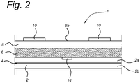
- Figures 1 to 2 respectively show a top view and a cross sectional view of a heating blanket 1 for providing a shrinkable sleeve on a pipe assembly according to the present invention.
- the heating blanket 1 comprises a heating sheet 2 provided with a pattern of resistance wiring 4 connectable to an electric power supply.
- the heating sheet 2 may in further embodiments be based on different types or combinations of heating techniques, e.g. using a heating medium.
- the pattern of resistance wiring 4 may typically comprise one or more U-turns of electrical resistance wires 4 connectable to the electrical power supply via a set of e.g. industrial electrical connectors 5.
- the pattern of resistance wiring/wires 4 may comprise a zigzag-like pattern for further increasing a surface coverage of the heating sheet 2 that can be heated electrically.
- the heating blanket 1 further comprises an insulation sheet 6 interposed between the heating sheet 2 and a pressure member 8, wherein the pressure member 8 is arranged for conformal engagement of the heating blanket 1 around the pipe assembly 3 during operation.
- the insulation sheet 6 is a viscoelastic insulation sheet 6 for conformal engagement thereof with the pipe assembly and a possibly present coating thereon, wherein the viscoelastic insulation sheet 6 may comprise a foam material, such as NASA foam.
- the heating blanket 1 of the present invention is a substantially flat and rectangular pliable sheet having one or more layers, such as the heating sheet 2 and insulation sheet 6.
- the one or more layers may be affixed together (e.g. stitched or glued) yielding a composite heating blanket 1 that can be handled as a single piece component to be wrapped around a pipe assembly.
- the one or more layers are not affixed together, so that each layer can be separately handled and wrapped around the pipe assembly if necessary.
- the heating blanket 1 may comprise two opposing ends 1a, 1b that overlap once the heating blanket 1 is looped or wrapped around a pipe assembly for heating thereof.
- the length L and width W of the heating blanket 1 may be adapted for virtually all pipe diameters, even for large pipe diameters such as 48 inch pipes or even larger.
- the pressure member 8 when applying the heating blanket 1 to a pipe assembly provided with a heat shrinkable sleeve, the pressure member 8 can be tightly fitted around the insulation sheet 6 and heating sheet 2, which are tightly wrapped or looped around the heat shrinkable sleeve.
- the pressure member 8 may then be configured for providing a distributed pressure or compression force on the insulation sheet 6 and heating sheet 2, so that he heating blanket 1 is able to absorb circumferential and longitudinal surface irregularities of the shrinkable sleeve and pipe assembly for optimal contact therewith.
- the pressure member 8 is particularly advantageous for e.g. field joints having a cutback of mainline pipe coating, thus wherein abutting and welded pipe ends are not covered by the mainline coating.
- the heating blanket 1 of the present invention is able to absorb various circumferential and longitudinal surface irregularities of such a cutback and can be snugly wrapped around the pipe assembly with a minimum of internal cavities disposed between the heating blanket 1 and the pipe assembly, e.g. between the heat shrinkable sleeve and heating sheet 2.
- heating blanket 1 Another advantage of the heating blanket 1 is that conformal engagement of the heating blanket 1 with a shrinkable sleeve disposed around a pipe assembly greatly reduces external disturbances of the heating process due to e.g. weather conditions. For example, in prior art systems there is often a considerable air gap interposed between the heat shrinkable sleeve and a heating apparatus used for shrinking the sleeve around a e.g. a field joint. With such systems , however, cold and windy weather conditions may disturb the heating process as cold wind may transport too much heat from the shrinkable sleeve and negatively influence the shrinking and bonding process to the pipe assembly.
- the heating blanket 1 of the present invention on the other hand minimizes and, in an advantageous embodiment, leaves no discernible and accessible air gap between the heating blanket 1 and the shrinkable sleeve as well as the pipe assembly.
- the heating blanket 1 ensures optimal temperature conditions for the shrinking and bonding process of the heat shrinkable sleeve in many weather conditions.
- the conformal engagement of the heating blanket 1 with the shrinkable sleeve and pipe assembly allows the heating blanket 1 to be used in e.g. explosive atmospheres, as explosive gases cannot penetrate the heating blanket 1 and the insulation sheet 6 is configured for keeping an outer surface of the heating blanket 1 at relative low temperatures, i.e. at least sufficiently low to avoid possible combustion.
- the insulation sheet 6 enables a gradual and homogenous heating of a heat shrinkable sleeve disposed around a pipe assembly.
- the insulation sheet 6 is a viscoelastic insulation sheet 6 configured for thermal insulation, e.g. a thermal viscoelastic insulation sheet 6.
- the viscoelastic insulation sheet 6 may comprise a foam material, such as NASA foam, for conformal engagement of the insulation sheet 6 with underlying contours of the heating sheet 2, the heat shrinkable sleeve and/or the pipe assembly and cutback region thereof.
- thermal insulation properties of the insulation sheet 6 enables gradual heating of the sleeve as generated heat is trapped between the pipe assembly and the heating blanket 1.
- the gradual and homogenous heating of the heat shrinkable sleeve also enables an evenly distributed and homogenous sleeve shrinkage, thereby providing an even and homogenous protective sleeve layer around a field joint once the shrinking and bonding process is completed.
- the insulation sheet 6 of the present invention may reduce the time to heat up the heating blanket 1 to operational temperatures from e.g. 8 minutes to 2 minutes.
- the homogenous heating process obtained with the heating blanket 1 allows various types of heat shrinkable sleeves to be used, such as soft mastic-based adhesive sleeves to "hot melt" sleeves utilizing hard adhesives.
- Hot melt sleeves used with prior art systems are known for requiring a preheated pipe assembly before an optimal shrinking and bonding process of the sleeve is possible.
- the heating blanket 1 of the present invention on the other hand is able to provide such hot melt sleeves on a pipe assembly without preheating the pipe assembly.
- the insulation sheet 6 allows for a gradual and homogenous build-up of heat throughout the sleeve without excessively overheating and possibly burning an inner and/or outer surface of the sleeve during shrinkage thereof.
- Hot melt sleeves with e.g. a hard HDPE backing layer can therefore be provided on the pipe assembly without overheating the backing layer, yet allowing the adhesive to flow and seal various surface irregularity of the pipe assembly during the bonding process of the sleeve.
- the insulation sheet 6 comprises an insulation material capable of withstanding temperatures up to 250° degrees Celsius, so that a large variety of heat shrinkable sleeves, including hot melt sleeves, can be heated over a wide temperature range.
- the pressure member 8 may be a releasable pressure member 8 that is easily positioned around the insulation sheet 6 and removed once the heat shrinkable sleeve has been properly applied.
- the pressure member 8 comprises a sheet material, e.g. a pliable sheet material, provided with one or more tensioning members 10.
- the tensioning members 10 may comprise a strap, such as webbing, provided with tensioning laces for connecting two opposing ends 1a, 1b of the heating blanket 1.
- the tensioning members 10 may comprise webbing with lashing straps for connecting two opposing end 1a, 1b of the heating blanket 1.
- the tensioning members 10 of the heating blanket 1 enable the pressure member 8 to be firmly tied around the pipe assembly for even compression of the insulation sheet 6 and the heating sheet 2 onto the heat shrinkable sleeve.
- the pressure member 8 may comprise one or more cylindrical sections of rigid material, such as two releasable clamping shell members configured for clamping the insulation sheet 6 and heating sheet 2 onto the heat shrinkable sleeve.
- the one or more cylindrical sections or clamping shell members may be provided with one or more tensioning members 10 as described above.
- the one or more tensioning members 10 may comprise one or more connecting strips for connecting facing end portions of the two releasable clamping shell members.
- a connecting strip may connect facing end portions of the two clamping shell members along a width thereof.
- At least one connecting strip may be a pliable connecting strip, allowing two facing end portions of the clamping shell members to remain pivotally connected at all times, thereby facilitating clamping the two clamping shell members around the pipe assembly when installing the heating blanket 1.
- the connecting strip may comprise a hinge or a continuous hinge for connecting two facing end portions of the two clamping shell members.
- the rigid material may be a fiber reinforced epoxy material, which may comprise glass fiber (GFK), carbon fiber (CFK), or even para-aramid synthetic fibers (e.g. "Kevlar”) and the like.
- the pressure member 8 may comprise two or more cylindrical sections of rigid material comprising glass reinforced epoxy, thereby providing e.g. thin, lightweight and strong clamping shell members.
- the pattern of resistance wiring 4 may comprise a plurality of sections (e.g. three) 4a, 4b, 4c, such as two side sections 4a, 4c and a mid section 4b.
- the sections 4a, 4b, 4c etc. of the pattern of resistance wiring 4 may be separately operable for segmented heating of the heat shrinkable sleeve, e.g. heating side section 4a, 4c first and then the mid section 4b or vice versa. Segmented heating can also be operated from right to left or vice versa.
- an appropriate segmented heating schedule may be chosen using the three heating sections 4a, 4b, 4c.
- the pattern of resistance wiring 4 may comprise any combination of two or more resistance wiring sections, e.g. six, to meet heating requirements of a particular sleeve for the shrinking and bonding process.
- the pattern of resistance wiring 4 is arranged for providing a specific heat capacity of at least 2W/cm 2 , e.g. 2.5 or 3 W/cm 2 .
- This heat capacity is sufficient for allowing gradual and homogenous heating to take place without overheating, or possibly burning, an inner or outer surface of the shrinkable sleeve.
- the specific heat capacity is sufficient for hot melt sleeves without preheating the pipe assembly.
- the pattern of resistance wiring 4 typically produces a temperature of about 80 degrees Celsius to 230 °C during operation.
- FIG. 2 shows a cross sectional view of the heating blanket 1 according to the present invention.
- the one or more tensioning members 10 are embodied as lashing straps disposed on an outer surface 8a of the pressure member 8 and the insulation sheet 6 is interposed between the pressure member 8 and the heating sheet 2, which may further comprise two, e.g. silicone based, layers 2a,2b with the pattern of resistance wiring 4 disposed there between.
- the silicone based layers 2a, 2b are advantageous, as they protect the pattern of resistance wiring 4 sufficiently. Also, this allows to use the heating blanket 1 for particular types of backing material used for the heat shrinkable sleeve, for example, wherein the silicone is able to work with shrinkable sleeves sold by Seal for life Industries.
- the heating blanket 1 may further comprise a control unit 12 connected to the pattern of resistance wiring 4.
- the control unit 12 may be configured for controlling the temperature of the pattern of resistance wiring 4 when the heating blanket 1 is operational.
- the control unit 12 may be arranged to control the two or more sections independently, such as the three sections 4a, 4b, 4c.
- the control unit 12 may be arranged to heat the outer sections 4a, 4c first and then heat up a mid section 4c or vice versa.
- control unit 12 is arranged to control an operational temperature in a temperature range between 80 to 230 °C during operation. This temperature range allows for many types of heat shrinkable sleeves to be applied to a pipe assembly, from soft mastic-based shrink sleeves to hard hot melt shrinkable sleeves with a stiff and hard backing material (e.g. HDPE) without preheating the pipe assembly.
- a stiff and hard backing material e.g. HDPE
- the heating blanket 1 may further comprise a temperature sensor 14 connected to the control unit 12.
- the temperature sensor 14 allows for accurate and timely measurement of the operational temperature when the heating blanket 1 is in use, wherein the control unit 12 may control the operational temperature based on measured temperatures by the temperature sensor 14.
- the temperature sensor 14 is disposed in the heating sheet 14 or on an outer surface thereof.
- Figure 3 shows a cross sectional view of a heating blanket 1 applied to a pipe assembly according to the present invention.
- the pipe assembly 3 is provided with a main line coating 3b and further comprises an abutting welded connection 3a of two pipe ends in a cutback region 3c thereof Note that the main line coating 3b is not present in the cutback region 3c.
- the pipe assembly 3 is further provided with a heat shrinkable sleeve 5 wrapped around the pipe assembly 3, in particular the mainline coating 3b and cutback region 3c.
- the shrinkable sleeve 5 overlaps the mainline coating 3b over a predetermined distance in a longitudinal direction thereof to ensure complete sealing and protection of the cutback region 3c.
- the heat shrinkable sleeve 5 comprises an adhesion layer 5a and a backing layer 5b, wherein the adhesion layer 5a is configured to melt at an operational temperature for filling surface irregularities of the pipe assembly 3, in particular the cutback region 3c, thereby protecting the field joint 3a against corrosion, fluids and particle ingress etc.
- the backing layer 5b is typically configured as a protective layer for the adhesion layer 5a and the field joint in general.
- the heating blanket 1 is wrapped or looped around the sleeve 5 in conformal engagement therewith, wherein the heating blanket 1 overlaps the shrinkable sleeve 5 and the mainline coating 3b in a longitudinal direction.
- the heating blanket 1 thus completely covers the shrinkable sleeve 5 for minimizing external disturbances while the heating blanket 1 is in operation. Since the shrinkable sleeve 5 is completely covered and enclosed by the heating blanket 1, heat losses are kept to a minimum so that a gradual and homogenous heating and shrinkage of the sleeve 5 is possible.
- the insulation sheet 6 then acts as a thermal barrier for trapping heat when the heating blanket 1 is in use.
- the pressure member 8 which in the depicted embodiment comprises a pliable sheet material 8 provided with one or more tensioning members 10 disposed on an outer surface 8a thereof.
- the one or more tensioning members 10 may be envisaged as lashing straps evenly distributed in the longitudinal direction of the pipe assembly 3 (i.e. along the width W of the heating blanket 1).
- the lashing straps 10 provide an even pressure or compression force to the pressure member 8 for tying the heating blanket 1 firmly to the pipe assembly 3.
- the heating blanket 1 of the present invention leaves no discernible air gap between the heat shrinkable sleeve 5 and the heating blanket 1, e.g. the heating sheet 2, so that cold and windy weather conditions have a minimal influence on the operational temperature while shrinking and bonding the sleeve to the pipe assembly 3. Furthermore, the risk that air can be trapped between the sleeve 5 and the pipe assembly 3 is reduced, ensuring lasting protection of the pipe assembly 3.
- the present invention relates to a method for shrinking a heat shrinkable sleeve 5 around a pipe assembly 3.
- a method for shrinking a heat shrinkable sleeve 5 around a pipe assembly 3 Reference is made to all Figure 1 to 3 for clarity.
- the method of the present invention comprises providing a heat shrinkable sleeve 5 around two abutting pipe ends of the pipe assembly 3.
- the pipe assembly 3 comprises a field joint 3a with cutback region 3c to be provided with corrosion and erosion protection, wherein the protective sleeve 5 comprises an adhesion layer 5a and a backing layer 5b.
- the method further comprises providing a heating blanket 1 around the sleeve 5 in conformal engagement therewith and operating the heating blanket 1 for shrinking the sleeve 5 around the pipe assembly 3 and adhering the sleeve (5) thereto.
- the conformal engagement of the heating blanket 1 with the heat shrinkable sleeve 5 provides high thermal efficiency during operation of the blanket 1, so that sleeve shrinkage and the bonding process of the sleeve 5 to the pipe assembly 3 is optimized.
- the heating blanket 1 acts as a thermal barrier that follows the circumferential and longitudinal profile of the shrink sleeve 5 and pipe assembly 3, thereby effectively trapping heat between the pipe assembly 3 and the heating blanket 1. Consequently, an even and homogenous heating and shrinkage of the sleeve 5 is obtained facilitating optimal operational melting temperatures for bonding the adhesion layer 5a to the pipe assembly 3.
- the backing layer 5b may comprise a high density polyethylene (HDPE), low density polyethylene (LDPE), or polypropylene (PP).
- the adhesion layer 5a may comprise a soft mastic adhesive or a hard holt melt adhesive.
- the backing layer 5b of the shrinkable sleeve 5 may have a thickness between 0.5 mm and 5 mm, so that the heating blanket is capable of heating many types of heat shrinkable sleeves to an operational temperature for the shrinking and bonding process.
- the method may also be applied to a pipe assembly 3 having pipe diameters in the range of at least 10 inch, e.g. even up to 56 inch.
- the heating blanket 1 has a relatively small size and low weight compared to prior art systems, so that it is easily wrapped or looped around large diameter pipes in conformal engagement therewith without the need for bulky and heavy equipment.
- the method of the present invention is suitable to be carried out by the heating blanket 1 disclosed above.
Landscapes
- Engineering & Computer Science (AREA)
- Mechanical Engineering (AREA)
- General Engineering & Computer Science (AREA)
- Physics & Mathematics (AREA)
- Thermal Sciences (AREA)
- Manufacturing & Machinery (AREA)
- Lining Or Joining Of Plastics Or The Like (AREA)
Claims (13)
- Couverture chauffante pour fournir un manchon rétractable sur un ensemble de tuyaux, comprenant
une nappe chauffante (2) ;
une nappe isolante (6) interposée entre la nappe chauffante (2) et
un élément de pression (8), l'élément de pression (8) étant disposé pour un engagement conforme de la couverture chauffante (1) autour de l'ensemble de tuyaux (3) pendant le fonctionnement,
dans lequel la nappe chauffante (2) est pourvue d'un motif de câblage de résistance (4) pouvant être connecté à une alimentation électrique, et caractérisée en ce que le motif du câblage de résistance (4) comprend deux ou plusieurs, par exemple trois, sections (4a, 4b, 4c). - Couverture chauffante selon la revendication 1, dans laquelle la nappe chauffante (2) comprend en outre deux couches à base de silicone (2a, 2b) entre lesquelles le motif de câblage de résistance (4) est disposé.
- Couverture chauffante selon la revendication 1 ou 2, dans laquelle le motif de câblage de résistance (4) est disposé pour fournir une capacité de chaleur spécifique d'au moins 2 W/cm2, par exemple 2,5 ou 3 W/cm2.
- Couverture chauffante selon l'une quelconque des revendications 1 à 3, dans laquelle l'élément de pression (8) comprend un matériau en nappe pourvu d'un ou plusieurs éléments de tension (10).
- Couverture chauffante selon l'une quelconque des revendications 1 à 4, dans laquelle l'élément de pression (8) comprend une ou plusieurs sections cylindriques de matériau rigide.
- Couverture chauffante selon l'une quelconque des revendications 1 à 5, comprenant en outre une unité de commande (12) connectée au motif de câblage de résistance (4) .
- Couverture chauffante selon la revendication 6, dans laquelle l'unité de commande (12) est disposée de manière à commander la température dans une gamme de températures entre 80 et 230° pendant le fonctionnement.
- Couverture chauffante selon la revendication 6 ou 7, comprenant en outre un capteur de température (14) connecté à l'unité de commande (12).
- Procédé de rétraction d'un manchon autour d'un ensemble de tuyaux, comprenant
une fourniture d'un manchon rétractable à la chaleur (5) autour de deux extrémités de tuyau adjacentes de l'ensemble de tuyaux (3), le manchon (5) comprenant une couche d'adhérence (5a) et une couche de support (5b) ;
une fourniture d'une couverture chauffante (1) selon l'une quelconque des revendications 1 à 8 autour du manchon en engagement conforme avec celui-ci ; et
une mise en fonctionnement de la couverture chauffante (1) pour rétracter le manchon (5) autour de l'ensemble de tuyaux (3) et faire adhérer le manchon (5) à celle-ci. - Procédé selon la revendication 9, dans lequel la couche de support (5b) comprend du polyéthylène à haute densité, du polyéthylène à basse densité ou du polypropylène.
- Procédé selon la revendication 9 ou 10, dans lequel la couche d'adhérence (5a) comprend un adhésif de mastic ou un adhésif thermofusible.
- Procédé selon l'une quelconque des revendications 9 à 11, dans lequel la couche de support (5b) a une épaisseur entre 0,5 mm et 5 mm.
- Procédé selon l'une quelconque des revendications 9 à 12, dans lequel l'ensemble de tuyaux (3) a un diamètre d'au moins 10 pouces.
Priority Applications (3)
| Application Number | Priority Date | Filing Date | Title |
|---|---|---|---|
| PL14181761T PL2987624T3 (pl) | 2014-08-21 | 2014-08-21 | Koc grzewczy |
| EP14181761.9A EP2987624B1 (fr) | 2014-08-21 | 2014-08-21 | Couverture chauffante |
| LTEP14181761.9T LT2987624T (lt) | 2014-08-21 | 2014-08-21 | Šildymo danga |
Applications Claiming Priority (1)
| Application Number | Priority Date | Filing Date | Title |
|---|---|---|---|
| EP14181761.9A EP2987624B1 (fr) | 2014-08-21 | 2014-08-21 | Couverture chauffante |
Publications (2)
| Publication Number | Publication Date |
|---|---|
| EP2987624A1 EP2987624A1 (fr) | 2016-02-24 |
| EP2987624B1 true EP2987624B1 (fr) | 2018-11-14 |
Family
ID=51359325
Family Applications (1)
| Application Number | Title | Priority Date | Filing Date |
|---|---|---|---|
| EP14181761.9A Not-in-force EP2987624B1 (fr) | 2014-08-21 | 2014-08-21 | Couverture chauffante |
Country Status (3)
| Country | Link |
|---|---|
| EP (1) | EP2987624B1 (fr) |
| LT (1) | LT2987624T (fr) |
| PL (1) | PL2987624T3 (fr) |
Families Citing this family (4)
| Publication number | Priority date | Publication date | Assignee | Title |
|---|---|---|---|---|
| US11438970B2 (en) | 2017-01-27 | 2022-09-06 | Purdue Research Foundation | Devices for heating small-diameter tubing and methods of making and using |
| EP3429042B1 (fr) | 2017-07-14 | 2022-08-03 | Tyco Electronics Raychem GmbH | Composant thermorétrécissable, et procédé d'assemblage d'un composant thermorétrécissable |
| EP3624288B1 (fr) * | 2018-09-12 | 2025-12-24 | Tyco Electronics Raychem GmbH | Procédé d'installation d'une enveloppe thermorétractable, kit d'installation et système d'installation |
| JP7547261B2 (ja) * | 2021-03-18 | 2024-09-09 | 株式会社日本製鋼所 | 溶融用ヒータ、および成形品の製造方法 |
Family Cites Families (4)
| Publication number | Priority date | Publication date | Assignee | Title |
|---|---|---|---|---|
| JPH0560286A (ja) * | 1991-08-30 | 1993-03-09 | Furukawa Electric Co Ltd:The | 樹脂管の接続方法 |
| ATE377269T1 (de) * | 2004-08-09 | 2007-11-15 | Airbus Gmbh | Erwärmungsmuffe zum schrumpfen von schrumpfmanschettenverbindungen |
| CA2658494A1 (fr) | 2009-03-13 | 2010-09-13 | Shawcor Ltd. | Appareil de chauffage pour manchons thermoretrecissables |
| US20130341320A1 (en) * | 2011-01-14 | 2013-12-26 | Shawcor Ltd. | Induction heating apparatus for pipeline connections |
-
2014
- 2014-08-21 LT LTEP14181761.9T patent/LT2987624T/lt unknown
- 2014-08-21 EP EP14181761.9A patent/EP2987624B1/fr not_active Not-in-force
- 2014-08-21 PL PL14181761T patent/PL2987624T3/pl unknown
Non-Patent Citations (1)
| Title |
|---|
| None * |
Also Published As
| Publication number | Publication date |
|---|---|
| LT2987624T (lt) | 2019-03-12 |
| PL2987624T3 (pl) | 2019-05-31 |
| EP2987624A1 (fr) | 2016-02-24 |
Similar Documents
| Publication | Publication Date | Title |
|---|---|---|
| EP2032340B1 (fr) | Procédé d'application d'une couche protectrice à un raccord de conduite | |
| CA2965374C (fr) | Appareil et systeme d'electro-fusion de canalisation en polyethylene | |
| EP2987624B1 (fr) | Couverture chauffante | |
| US4096017A (en) | Method and article for forming field joints on pipe coated with thermoplastic material | |
| AU744364B2 (en) | Apparatus for forming field joints on plastic coated pipe | |
| US8840977B2 (en) | Casing member for forming a connection between tubular sections and use thereof for forming connections | |
| ITGE980101A1 (it) | Metodo per la protezione anticorrosiva in campo dei giunti disaldatura e/o delle zone di rivestimento danneggiate di tubazioni | |
| KR20140089429A (ko) | 튜브형 제품을 위한 다수의 순차적 사용 적외선 가열 영역들을 포함하는 장치 | |
| CA1286869C (fr) | Article thermoretrecissable | |
| US9821508B2 (en) | Apparatus for applying heat shrinkable casings onto preinsulated pipe joints | |
| CN112673536B (zh) | 安装热收缩盖的方法、安装套件及安装系统 | |
| US10272652B2 (en) | Heat shrink laminated composite patch for repairing composite components | |
| ITMI20070414A1 (it) | Metodo e apparecchiatura per realizzare uno strato protettivo attorno ad una porzione anulare di giunzione fra spezzoni di tubo atti a realizzare una tubazione subacquea e natante di posa di tubazioni subacquee comprendente tale apparecchiatura | |
| WO2008079831A1 (fr) | Procédé d'utilisation d'articles thermorétractables | |
| JP2006194368A (ja) | 現地溶接部の防食被覆構造 | |
| CN207449149U (zh) | 至少两个聚烯烃管状部件端对端接合的系统 | |
| US5560847A (en) | Environmental protection of a pipe by means of a conductive polymer sheet | |
| CN101460293A (zh) | 向管接头施加保护层的方法 | |
| NZ231452A (en) | Splice sealing with heated tape | |
| JP2004169811A (ja) | 樹脂管管端部の保護方法 | |
| JPH04108893U (ja) | 熱収縮性保護体の加熱治具 |
Legal Events
| Date | Code | Title | Description |
|---|---|---|---|
| PUAI | Public reference made under article 153(3) epc to a published international application that has entered the european phase |
Free format text: ORIGINAL CODE: 0009012 |
|
| AK | Designated contracting states |
Kind code of ref document: A1 Designated state(s): AL AT BE BG CH CY CZ DE DK EE ES FI FR GB GR HR HU IE IS IT LI LT LU LV MC MK MT NL NO PL PT RO RS SE SI SK SM TR |
|
| AX | Request for extension of the european patent |
Extension state: BA ME |
|
| 17P | Request for examination filed |
Effective date: 20160715 |
|
| RBV | Designated contracting states (corrected) |
Designated state(s): AL AT BE BG CH CY CZ DE DK EE ES FI FR GB GR HR HU IE IS IT LI LT LU LV MC MK MT NL NO PL PT RO RS SE SI SK SM TR |
|
| GRAP | Despatch of communication of intention to grant a patent |
Free format text: ORIGINAL CODE: EPIDOSNIGR1 |
|
| STAA | Information on the status of an ep patent application or granted ep patent |
Free format text: STATUS: GRANT OF PATENT IS INTENDED |
|
| RIC1 | Information provided on ipc code assigned before grant |
Ipc: B29C 65/00 20060101ALN20180628BHEP Ipc: B29C 65/68 20060101ALN20180628BHEP Ipc: B29C 63/42 20060101AFI20180628BHEP |
|
| INTG | Intention to grant announced |
Effective date: 20180713 |
|
| GRAS | Grant fee paid |
Free format text: ORIGINAL CODE: EPIDOSNIGR3 |
|
| GRAA | (expected) grant |
Free format text: ORIGINAL CODE: 0009210 |
|
| STAA | Information on the status of an ep patent application or granted ep patent |
Free format text: STATUS: THE PATENT HAS BEEN GRANTED |
|
| AK | Designated contracting states |
Kind code of ref document: B1 Designated state(s): AL AT BE BG CH CY CZ DE DK EE ES FI FR GB GR HR HU IE IS IT LI LT LU LV MC MK MT NL NO PL PT RO RS SE SI SK SM TR |
|
| REG | Reference to a national code |
Ref country code: CH Ref legal event code: EP Ref country code: AT Ref legal event code: REF Ref document number: 1064284 Country of ref document: AT Kind code of ref document: T Effective date: 20181115 |
|
| REG | Reference to a national code |
Ref country code: DE Ref legal event code: R096 Ref document number: 602014035904 Country of ref document: DE |
|
| REG | Reference to a national code |
Ref country code: IE Ref legal event code: FG4D |
|
| REG | Reference to a national code |
Ref country code: RO Ref legal event code: EPE |
|
| REG | Reference to a national code |
Ref country code: NL Ref legal event code: FP |
|
| PG25 | Lapsed in a contracting state [announced via postgrant information from national office to epo] |
Ref country code: BG Free format text: LAPSE BECAUSE OF FAILURE TO SUBMIT A TRANSLATION OF THE DESCRIPTION OR TO PAY THE FEE WITHIN THE PRESCRIBED TIME-LIMIT Effective date: 20190214 Ref country code: NO Free format text: LAPSE BECAUSE OF FAILURE TO SUBMIT A TRANSLATION OF THE DESCRIPTION OR TO PAY THE FEE WITHIN THE PRESCRIBED TIME-LIMIT Effective date: 20190214 Ref country code: HR Free format text: LAPSE BECAUSE OF FAILURE TO SUBMIT A TRANSLATION OF THE DESCRIPTION OR TO PAY THE FEE WITHIN THE PRESCRIBED TIME-LIMIT Effective date: 20181114 Ref country code: FI Free format text: LAPSE BECAUSE OF FAILURE TO SUBMIT A TRANSLATION OF THE DESCRIPTION OR TO PAY THE FEE WITHIN THE PRESCRIBED TIME-LIMIT Effective date: 20181114 Ref country code: IS Free format text: LAPSE BECAUSE OF FAILURE TO SUBMIT A TRANSLATION OF THE DESCRIPTION OR TO PAY THE FEE WITHIN THE PRESCRIBED TIME-LIMIT Effective date: 20190314 Ref country code: ES Free format text: LAPSE BECAUSE OF FAILURE TO SUBMIT A TRANSLATION OF THE DESCRIPTION OR TO PAY THE FEE WITHIN THE PRESCRIBED TIME-LIMIT Effective date: 20181114 |
|
| PG25 | Lapsed in a contracting state [announced via postgrant information from national office to epo] |
Ref country code: PT Free format text: LAPSE BECAUSE OF FAILURE TO SUBMIT A TRANSLATION OF THE DESCRIPTION OR TO PAY THE FEE WITHIN THE PRESCRIBED TIME-LIMIT Effective date: 20190314 Ref country code: GR Free format text: LAPSE BECAUSE OF FAILURE TO SUBMIT A TRANSLATION OF THE DESCRIPTION OR TO PAY THE FEE WITHIN THE PRESCRIBED TIME-LIMIT Effective date: 20190215 Ref country code: RS Free format text: LAPSE BECAUSE OF FAILURE TO SUBMIT A TRANSLATION OF THE DESCRIPTION OR TO PAY THE FEE WITHIN THE PRESCRIBED TIME-LIMIT Effective date: 20181114 Ref country code: SE Free format text: LAPSE BECAUSE OF FAILURE TO SUBMIT A TRANSLATION OF THE DESCRIPTION OR TO PAY THE FEE WITHIN THE PRESCRIBED TIME-LIMIT Effective date: 20181114 Ref country code: AL Free format text: LAPSE BECAUSE OF FAILURE TO SUBMIT A TRANSLATION OF THE DESCRIPTION OR TO PAY THE FEE WITHIN THE PRESCRIBED TIME-LIMIT Effective date: 20181114 |
|
| PG25 | Lapsed in a contracting state [announced via postgrant information from national office to epo] |
Ref country code: CZ Free format text: LAPSE BECAUSE OF FAILURE TO SUBMIT A TRANSLATION OF THE DESCRIPTION OR TO PAY THE FEE WITHIN THE PRESCRIBED TIME-LIMIT Effective date: 20181114 Ref country code: DK Free format text: LAPSE BECAUSE OF FAILURE TO SUBMIT A TRANSLATION OF THE DESCRIPTION OR TO PAY THE FEE WITHIN THE PRESCRIBED TIME-LIMIT Effective date: 20181114 |
|
| REG | Reference to a national code |
Ref country code: DE Ref legal event code: R097 Ref document number: 602014035904 Country of ref document: DE |
|
| PG25 | Lapsed in a contracting state [announced via postgrant information from national office to epo] |
Ref country code: SM Free format text: LAPSE BECAUSE OF FAILURE TO SUBMIT A TRANSLATION OF THE DESCRIPTION OR TO PAY THE FEE WITHIN THE PRESCRIBED TIME-LIMIT Effective date: 20181114 Ref country code: SK Free format text: LAPSE BECAUSE OF FAILURE TO SUBMIT A TRANSLATION OF THE DESCRIPTION OR TO PAY THE FEE WITHIN THE PRESCRIBED TIME-LIMIT Effective date: 20181114 Ref country code: EE Free format text: LAPSE BECAUSE OF FAILURE TO SUBMIT A TRANSLATION OF THE DESCRIPTION OR TO PAY THE FEE WITHIN THE PRESCRIBED TIME-LIMIT Effective date: 20181114 |
|
| PLBE | No opposition filed within time limit |
Free format text: ORIGINAL CODE: 0009261 |
|
| STAA | Information on the status of an ep patent application or granted ep patent |
Free format text: STATUS: NO OPPOSITION FILED WITHIN TIME LIMIT |
|
| 26N | No opposition filed |
Effective date: 20190815 |
|
| PG25 | Lapsed in a contracting state [announced via postgrant information from national office to epo] |
Ref country code: SI Free format text: LAPSE BECAUSE OF FAILURE TO SUBMIT A TRANSLATION OF THE DESCRIPTION OR TO PAY THE FEE WITHIN THE PRESCRIBED TIME-LIMIT Effective date: 20181114 |
|
| REG | Reference to a national code |
Ref country code: AT Ref legal event code: UEP Ref document number: 1064284 Country of ref document: AT Kind code of ref document: T Effective date: 20181114 |
|
| PG25 | Lapsed in a contracting state [announced via postgrant information from national office to epo] |
Ref country code: LI Free format text: LAPSE BECAUSE OF NON-PAYMENT OF DUE FEES Effective date: 20190831 Ref country code: LU Free format text: LAPSE BECAUSE OF NON-PAYMENT OF DUE FEES Effective date: 20190821 Ref country code: MC Free format text: LAPSE BECAUSE OF FAILURE TO SUBMIT A TRANSLATION OF THE DESCRIPTION OR TO PAY THE FEE WITHIN THE PRESCRIBED TIME-LIMIT Effective date: 20181114 Ref country code: CH Free format text: LAPSE BECAUSE OF NON-PAYMENT OF DUE FEES Effective date: 20190831 |
|
| PG25 | Lapsed in a contracting state [announced via postgrant information from national office to epo] |
Ref country code: IE Free format text: LAPSE BECAUSE OF NON-PAYMENT OF DUE FEES Effective date: 20190821 |
|
| PGFP | Annual fee paid to national office [announced via postgrant information from national office to epo] |
Ref country code: PL Payment date: 20200529 Year of fee payment: 7 |
|
| PGFP | Annual fee paid to national office [announced via postgrant information from national office to epo] |
Ref country code: NL Payment date: 20200814 Year of fee payment: 7 |
|
| PGFP | Annual fee paid to national office [announced via postgrant information from national office to epo] |
Ref country code: LT Payment date: 20200724 Year of fee payment: 7 Ref country code: GB Payment date: 20200813 Year of fee payment: 7 Ref country code: TR Payment date: 20200818 Year of fee payment: 7 Ref country code: DE Payment date: 20200812 Year of fee payment: 7 Ref country code: RO Payment date: 20200724 Year of fee payment: 7 Ref country code: FR Payment date: 20200715 Year of fee payment: 7 |
|
| PGFP | Annual fee paid to national office [announced via postgrant information from national office to epo] |
Ref country code: AT Payment date: 20200728 Year of fee payment: 7 Ref country code: IT Payment date: 20200713 Year of fee payment: 7 Ref country code: LV Payment date: 20200730 Year of fee payment: 7 Ref country code: BE Payment date: 20200715 Year of fee payment: 7 |
|
| PG25 | Lapsed in a contracting state [announced via postgrant information from national office to epo] |
Ref country code: CY Free format text: LAPSE BECAUSE OF FAILURE TO SUBMIT A TRANSLATION OF THE DESCRIPTION OR TO PAY THE FEE WITHIN THE PRESCRIBED TIME-LIMIT Effective date: 20181114 |
|
| PG25 | Lapsed in a contracting state [announced via postgrant information from national office to epo] |
Ref country code: MT Free format text: LAPSE BECAUSE OF FAILURE TO SUBMIT A TRANSLATION OF THE DESCRIPTION OR TO PAY THE FEE WITHIN THE PRESCRIBED TIME-LIMIT Effective date: 20181114 Ref country code: HU Free format text: LAPSE BECAUSE OF FAILURE TO SUBMIT A TRANSLATION OF THE DESCRIPTION OR TO PAY THE FEE WITHIN THE PRESCRIBED TIME-LIMIT; INVALID AB INITIO Effective date: 20140821 |
|
| REG | Reference to a national code |
Ref country code: DE Ref legal event code: R119 Ref document number: 602014035904 Country of ref document: DE |
|
| REG | Reference to a national code |
Ref country code: LT Ref legal event code: MM4D Effective date: 20210821 |
|
| REG | Reference to a national code |
Ref country code: NL Ref legal event code: MM Effective date: 20210901 |
|
| REG | Reference to a national code |
Ref country code: AT Ref legal event code: MM01 Ref document number: 1064284 Country of ref document: AT Kind code of ref document: T Effective date: 20210821 |
|
| REG | Reference to a national code |
Ref country code: BE Ref legal event code: MM Effective date: 20210831 |
|
| GBPC | Gb: european patent ceased through non-payment of renewal fee |
Effective date: 20210821 |
|
| PG25 | Lapsed in a contracting state [announced via postgrant information from national office to epo] |
Ref country code: LT Free format text: LAPSE BECAUSE OF NON-PAYMENT OF DUE FEES Effective date: 20210821 Ref country code: AT Free format text: LAPSE BECAUSE OF NON-PAYMENT OF DUE FEES Effective date: 20210821 |
|
| PG25 | Lapsed in a contracting state [announced via postgrant information from national office to epo] |
Ref country code: RO Free format text: LAPSE BECAUSE OF NON-PAYMENT OF DUE FEES Effective date: 20210821 Ref country code: LV Free format text: LAPSE BECAUSE OF NON-PAYMENT OF DUE FEES Effective date: 20210821 |
|
| PG25 | Lapsed in a contracting state [announced via postgrant information from national office to epo] |
Ref country code: NL Free format text: LAPSE BECAUSE OF NON-PAYMENT OF DUE FEES Effective date: 20210901 Ref country code: MK Free format text: LAPSE BECAUSE OF FAILURE TO SUBMIT A TRANSLATION OF THE DESCRIPTION OR TO PAY THE FEE WITHIN THE PRESCRIBED TIME-LIMIT Effective date: 20181114 |
|
| PG25 | Lapsed in a contracting state [announced via postgrant information from national office to epo] |
Ref country code: IT Free format text: LAPSE BECAUSE OF NON-PAYMENT OF DUE FEES Effective date: 20210821 Ref country code: GB Free format text: LAPSE BECAUSE OF NON-PAYMENT OF DUE FEES Effective date: 20210821 Ref country code: FR Free format text: LAPSE BECAUSE OF NON-PAYMENT OF DUE FEES Effective date: 20210831 Ref country code: DE Free format text: LAPSE BECAUSE OF NON-PAYMENT OF DUE FEES Effective date: 20220301 Ref country code: BE Free format text: LAPSE BECAUSE OF NON-PAYMENT OF DUE FEES Effective date: 20210831 |
|
| PG25 | Lapsed in a contracting state [announced via postgrant information from national office to epo] |
Ref country code: PL Free format text: LAPSE BECAUSE OF NON-PAYMENT OF DUE FEES Effective date: 20210821 |
|
| PG25 | Lapsed in a contracting state [announced via postgrant information from national office to epo] |
Ref country code: TR Free format text: LAPSE BECAUSE OF NON-PAYMENT OF DUE FEES Effective date: 20210821 |