EP2987663B1 - Système d'assistance au conducteur pour un attelage de véhicule utilitaire et procédé d'exécution d'un processus d'attelage - Google Patents
Système d'assistance au conducteur pour un attelage de véhicule utilitaire et procédé d'exécution d'un processus d'attelage Download PDFInfo
- Publication number
- EP2987663B1 EP2987663B1 EP15000914.0A EP15000914A EP2987663B1 EP 2987663 B1 EP2987663 B1 EP 2987663B1 EP 15000914 A EP15000914 A EP 15000914A EP 2987663 B1 EP2987663 B1 EP 2987663B1
- Authority
- EP
- European Patent Office
- Prior art keywords
- coupling
- semitrailer
- assistance system
- driver assistance
- driver
- Prior art date
- Legal status (The legal status is an assumption and is not a legal conclusion. Google has not performed a legal analysis and makes no representation as to the accuracy of the status listed.)
- Active
Links
Images


Classifications
-
- B—PERFORMING OPERATIONS; TRANSPORTING
- B60—VEHICLES IN GENERAL
- B60R—VEHICLES, VEHICLE FITTINGS, OR VEHICLE PARTS, NOT OTHERWISE PROVIDED FOR
- B60R1/00—Optical viewing arrangements; Real-time viewing arrangements for drivers or passengers using optical image capturing systems, e.g. cameras or video systems specially adapted for use in or on vehicles
- B60R1/20—Real-time viewing arrangements for drivers or passengers using optical image capturing systems, e.g. cameras or video systems specially adapted for use in or on vehicles
- B60R1/22—Real-time viewing arrangements for drivers or passengers using optical image capturing systems, e.g. cameras or video systems specially adapted for use in or on vehicles for viewing an area outside the vehicle, e.g. the exterior of the vehicle
- B60R1/23—Real-time viewing arrangements for drivers or passengers using optical image capturing systems, e.g. cameras or video systems specially adapted for use in or on vehicles for viewing an area outside the vehicle, e.g. the exterior of the vehicle with a predetermined field of view
- B60R1/26—Real-time viewing arrangements for drivers or passengers using optical image capturing systems, e.g. cameras or video systems specially adapted for use in or on vehicles for viewing an area outside the vehicle, e.g. the exterior of the vehicle with a predetermined field of view to the rear of the vehicle
-
- B—PERFORMING OPERATIONS; TRANSPORTING
- B60—VEHICLES IN GENERAL
- B60D—VEHICLE CONNECTIONS
- B60D1/00—Traction couplings; Hitches; Draw-gear; Towing devices
- B60D1/58—Auxiliary devices
- B60D1/62—Auxiliary devices involving supply lines, electric circuits or the like
-
- B—PERFORMING OPERATIONS; TRANSPORTING
- B60—VEHICLES IN GENERAL
- B60D—VEHICLE CONNECTIONS
- B60D1/00—Traction couplings; Hitches; Draw-gear; Towing devices
- B60D1/24—Traction couplings; Hitches; Draw-gear; Towing devices characterised by arrangements for particular functions
- B60D1/36—Traction couplings; Hitches; Draw-gear; Towing devices characterised by arrangements for particular functions for facilitating connection, e.g. hitch catchers
-
- B—PERFORMING OPERATIONS; TRANSPORTING
- B62—LAND VEHICLES FOR TRAVELLING OTHERWISE THAN ON RAILS
- B62D—MOTOR VEHICLES; TRAILERS
- B62D53/00—Tractor-trailer combinations; Road trains
- B62D53/04—Tractor-trailer combinations; Road trains comprising a vehicle carrying an essential part of the other vehicle's load by having supporting means for the front or rear part of the other vehicle
- B62D53/08—Fifth wheel traction couplings
-
- B—PERFORMING OPERATIONS; TRANSPORTING
- B60—VEHICLES IN GENERAL
- B60R—VEHICLES, VEHICLE FITTINGS, OR VEHICLE PARTS, NOT OTHERWISE PROVIDED FOR
- B60R2300/00—Details of viewing arrangements using cameras and displays, specially adapted for use in a vehicle
- B60R2300/80—Details of viewing arrangements using cameras and displays, specially adapted for use in a vehicle characterised by the intended use of the viewing arrangement
- B60R2300/808—Details of viewing arrangements using cameras and displays, specially adapted for use in a vehicle characterised by the intended use of the viewing arrangement for facilitating docking to a trailer
Definitions
- the invention relates to a driver assistance system of a utility vehicle combination according to the preamble of claim 1 and to a method for carrying out a coupling process according to the preamble of claim 15.
- a commercial vehicle combination as a semitrailer consists of a towing vehicle and a semi-trailer.
- a commercial vehicle combination as an articulated train consists of a towing vehicle and a trailer. Both embodiments each have a coupling device, with a zug scholar devisen, lockable coupling receiving part and an associated, retractable into the coupling receiving part coupling element on the trailer / trailer.
- the towing vehicle-side coupling-receiving part is a known coupling plate with a rearwardly open Einfahrschlitz and a coupling lock and the semi-trailer coupling element is a of a trailer plate downwardly projecting kingpins as a so-called kingpin.
- the towing vehicle-side coupling receiving part is usually designed as known per se with a jaw opening open to the rear and the trailer-side coupling element consists of a drawbar eye on a drawbar of the trailer.
- Such video cameras are used both as maneuvering aids and for the detection of obstacles in the vicinity of the utility vehicle combination, in particular in blind spot areas. This also clearly recognizes persons, in particular pedestrians and cyclists, who are located in safety-critical areas, which are not visible with exterior mirrors, in the vicinity of the utility vehicle combination.
- Such video cameras are thus intended to assist the driver in driving the coupled utility vehicle combination and thereby regularly arranged laterally and high, for example, as a "bird-view" cameras on towing vehicle. Effective support of the driver during the coupling process is not possible with these video cameras because of the inappropriate perspective, since neither the retracting area for the coupling element on the coupling receiving part nor the coupling element itself is appropriately detected and imaged in the video image.
- the Ankuppelvorgang in a commercial vehicle combination is previously a costly measure for the driver, since when resetting the towing vehicle, the two associated coupling parts on towing vehicle and semi-trailer / trailer, in particular by aligning over the mirrors optionally supported by several inspection gears, merged in the horizontal and in height Need to become. Since towing vehicle teams are usually only moved with one driver, a guiding helper is not available on a regular basis. An Ankuppelvorgang can thus be time consuming with multiple failed attempts.
- a driver assistance system is known, by means of which a driver is assisted in coupling a trailer to a towing vehicle.
- at least one video camera is arranged behind a coupling receiving part of the towing vehicle, by means of which, as seen in the vehicle longitudinal direction, detected in front of the video camera area and can be mapped in a first video image.
- a region located behind the video camera, seen in the longitudinal direction of the vehicle can also be detected and imaged in a second video image.
- DE 10 2004 029 130 A1 discloses a driver assistance system by means of which a driver is assisted in coupling the trailer to a towing vehicle by means of a camera.
- This camera is arranged in the region of a fifth wheel of the towing vehicle and directed to the rear, so that by means of the camera image data or images of a coupling area of the trailer can be recorded.
- the object of the invention is to propose a driver assistance system of a commercial vehicle combination, with a Ankuppelvorgang is safe, fast and convenient to carry out. Furthermore, it is an object of the present invention to propose a method for carrying out such a coupling process.
- a driver assistance system for a utility vehicle combination wherein the utility vehicle combination is constructed as a semitrailer from a towing vehicle and a semi-trailer, wherein a coupling device is provided, the zugterrorism discoveredes, lockable coupling receiving part and an associated, retractable into the coupling receiving part coupling element on the trailer, and wherein zugterrorism spirit a rear-view camera device is provided with a video camera and with an associated screen for a video image in the field of view of a driver.
- the video camera in particular for carrying out a coupling process, is associated with the coupling receiving part (in particular in the direction of travel in front of the coupling receiving part or in the coupling receiving part) that the area of the coupling receiving part and a rearward Environment can be detected with the coupling element and in the video image can be mapped, wherein in the video image visible to the driver guide mark is displayed as Peil Anlagen mark that visualizes the retraction area for the coupling element on the coupling-receiving part.
- the driver receives a video image on which he sees both the coupling receiving part and the coupling element.
- the coupling element on the trailer passes into the retraction area of the towing vehicle-side coupling receiving part. Since this retraction area is directed to a coupling plate as rearwardly open Einfahrschlitz to the rear and thus neither the driver nor the video camera is directly detected and visible, a guide mark is displayed as a direction finder at this point.
- the driver has a very accurate Peil Anlagenkeit, which makes a Ankuppelvorgang quickly, easily and conveniently.
- the guide mark can be designed as a vertical superimposed guideline.
- this then runs through the vehicle in the longitudinal direction rearwardly open conical Einfahrschlitz and must be aligned for horizontal bearing with the kingpin or the kingpin on the trailer plate of the trailer.
- the location of such a vertical guideline is determined by the geometric conditions on the tractor and therefore immutable in the video image, so that the generation and display of the guideline is easy to carry out.
- Such a vertical guideline is already a valuable finding aid for the driver.
- the guide mark is formed in the video image in the manner of a "destination cross", which consists of the vertical guideline and a horizontal height auxiliary line is, which visualizes a relevant for the coupling process altitude on the towing vehicle.
- the location of such a height auxiliary line depends on the geometric conditions of the towing vehicle and is thus constantly displayed in the video image, so that such a display is easy to carry out.
- the horizontal fatigueninsline can advantageously visualize the altitude of the top of a clutch plate, in particular a tiltable about a vehicle transverse axis coupling plate in the coupling point, or the center of a clutch lock a clutch plate, in particular to assist the driver in the vertical height adjustment between the clutch plate and the trailer plate together with the drawbar or kingpin, wherein the trailer plate is preferably traversed during Ankuppelvorgang with an intermediate gap.
- the driver with the "target cross" is a very good Peil bride available.
- an image processing device in particular an image processing device with at least one image processing algorithm, is provided by means of a front in the direction of travel lower edge of the semitrailer semitrailer and / or such defined components of the semi-trailer semitrailer, which during Ankuppelvorgang a height assessment of the relative position between the Enable coupling plate and the trailer plate and / or a kingpin, detectable, in particular automatically detectable, is or are.
- the detected elements or components are then displayed in the video image by means of at least one guidance mark, in particular by means of a horizontal guideline, and displayed to the driver.
- Such a height estimation is essential because when approaching the towing vehicle to the semi-trailer, the clutch plate moves under the trailer plate with a height gap, the driver with the help of a pneumatic device for raising / lowering of the towing vehicle must compensate, so that the clutch plate flush with the Trailer plate is.
- the driver can advantageously use the guide marks, in particular horizontal guidelines. Accordingly, a device for raising / lowering the towing vehicle as well as alternatively or additionally the trailer is provided, by means of which a height compensation during Ankuppelvorgang by evaluation of image data for relative position between the clutch-receiving part and the coupling element is feasible, in particular automatically carried out.
- a further improvement and refinement of the system can be achieved by providing a device for determining and / or estimating the horizontal distance the approach between the coupling-receiving part and the coupling element, in particular when approaching between a coupling plate and a kingpin of the semitrailer, is provided, wherein at least one distance clarifying auxiliary mark as an element of a guide mark or, forming an element of a guide mark virtual shape in the Video image is fade in.
- helpful information can also be made available to the driver with regard to a relevant distance.
- Such at least one auxiliary marker as a distance determination aid, which reproduces the relative coupling position may consist of at least one guideline displayed in the video image, which at defined distances between towing vehicle and semi-trailer with at least one defined Kant, in particular with at least one associated outer edges of the trailer agree and / or consist of at least one visualized virtual form, which coincide in terms of size at a defined distance between towing vehicle and semi-trailer with defined components of the trailer or its shape.
- the fact is taken into account that the image of the trailer shown in the video image is the smaller, the greater the distance between towing vehicle and semitrailer, with a match of the superimposed and the currently detected semitrailer forms can be made in particular when reaching the Ankuppticians.
- the size comparison by the driver in the video image can be performed by inspection. Also by an image processing device such a size comparison can be performed, e.g. the currently detected size of a component is compared with the known stored and standardized real size of this component. The actual distance can then be determined from this current size comparison and displayed numerically and / or graphically to the driver.
- the size comparison with the help of standardized components, such as the kingpin is advantageous regardless of the individual size and shape of a trailer and is therefore suitable for all semi-trailers universal.
- the relative distance can also be determined by other devices known per se, in particular by means of ultrasonic sensors or radar sensors, and displayed to the driver.
- an adaptation device can be provided, by means of which at least part of the elements forming the guide marking, in particular guidelines and / or auxiliary markings and / or a target cross, in the color and / or in the transparency and / or in the form of the visualization conditions and / or tolerance ranges and / or physically possible areas stationary or dynamically depending on the progress in Ankuppelvorgang are automatically or manually adjustable.
- the guide marks and / or auxiliary markings and / or a target cross can thus be designed differently depending on the requirements and visualization conditions or can also be individually adapted during the coupling process.
- the width of the vertical guideline correspond to the tolerance range of the Einfahrschlitzes the fifth wheel.
- the length of the vertical guideline can be limited to a physically possible range.
- the "target cross” can also be visualized by other forms of representation, which enable a targeting of the target area. This may in particular be a circle with adaptable / dynamic radius or an ellipse with adjustable / dynamic half-axes.
- a zoom device is provided, by means of which the image section displayed in or as a video image can be changed in size manually or in particular automatically, in particular as a function of the coupling process. This helps the driver to carry out the coupling process even easier.
- the position and orientation of the video camera is an essential feature. Particularly simple and functional perspective conditions are obtained when the video camera is positioned on the towing vehicle of the semitrailer so that its optical axis in the vehicle longitudinal center is horizontal at the height of the upper edge of the fifth wheel or by the coupling point of a tiltable coupling plate.
- the "target cross" is centrally located in the video image and in the direction of the trajectory and reverse drive of the towing vehicle in the direction of the kingpin occur no perspective changes or distortions.
- the "target cross” can be supplemented by an inserted "traffic cone” whose cone angle and cone axis in the direction of the deviation are aligned.
- the traffic cone can be flattened in the region of the "target cross” with a "cone bottom” whose width can correspond to the lateral tolerance range of Einkuppelstelle.
- the video camera is expediently fastened to the rear wall of the cab cab or to the frame on the vehicle frame, in particular on a rail extending there in the Z direction.
- this can be activated automatically and / or as required by the driver as a function of operating conditions of the vehicle, in particular an engaged reverse gear.
- the number and types of the guide marks and / or auxiliary markings described above can be activated manually or automatically by the driver in terms of their position, size and shape, transparency, magnifications, etc., as required.
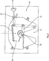
- FIG. 1 is a schematic side view of a tractor unit 1 with a towing vehicle 2 and a trailer 3 shown at a Ankuppelvorgang.
- a coupling plate 4 is arranged in a conventional manner, as in a plan view with further details in Fig. 2 shown is:
- the clutch plate 4 has, in particular, a retraction slot 5 which is open towards the rear and which narrows to form a lockable clutch lock 6.
- Functional elements of the locking lock 6 are a tension spring 7, a safety lever 8, a hand lever 9, a coupling hook 10 and a locking wedge 11 as a locking pawl.
- the in Fig. 1 semi-trailer 3 shown only partially is supported in its front region with preferably a plurality of supports 12 so that a kingpin 13 projects as a kingpin 13 in front of the supports 12 at a lower trailer plate 24 for a Ankuppelvorgang freely down.
- the task of the driver is to reset the towing vehicle 2 during the coupling process and to position it so that the kingpin 13 passes through the retraction slot 5 in the coupling plate 4 into the region of the locking lock 6 and can be locked there.
- the driver assistance system according to the invention is attached: This has inter alia a video camera 14 and an associated screen 15 in the field of vision of a driver, on which the captured video image is shown.
- the video camera 14 is mounted in the direction of travel in front of the coupling plate 4 on a rail 16 on a cab rear wall 33 and aligned so that their optical axis 45 (visual beam) in the vehicle longitudinal center is horizontal at the height of the upper edge of the fifth wheel 4 and the locking lock 6 ,
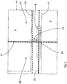
- a video image 17 is shown as it is currently displayed on the screen 15.
- the coupling plate 4 can be seen and a horizontal upper edge 18 of the vehicle body.
- the front lower edge 19 (visualized by a row of points) of the trailer 3 can be seen as well as the rearwardly offset and downwardly projecting kingpin 13, which is visible through the specified position and orientation of the video camera 14 on the video image 17.
- the towing vehicle 2 is positioned in front of the trailer 3 for a Ankuppelvorgang only relatively "coarse", the kingpin 13 with respect to the clutch plate 4 is still relatively far offset laterally and in height.
- a "target cross" 20 is inserted into video image 17 consisting of a vertical guideline 21 through the longitudinal center of the retracting slot 5 (practically invisible to a driver) the coupling plate 4 and from a horizontal contour line 22, which visualizes the height of the top of the horizontally oriented coupling plate 4 in the coupling point or in the middle of the locking lock 6.
- the clutch plate 4 is mounted here within certain limits rotatably about the y-axis and shown in a tilted position, so that when viewing the video image (without superimposed 22) the exact height of the top of the coupling plate 4 in the coupling point can not be exactly viewed or estimated.
- the superimposed horizontal contour line 22 helps the driver with a suitable assessment, especially with tilted clutch plate. 4
- the detection of the front lower edge 19 of the semi-trailer 3 or other components which allow height estimation can be carried out automatically with the aid of image processing algorithms. Furthermore, the height compensation can also be done automatically as a whole.
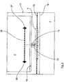
- a video image 17 is shown with further markings and virtual shapes as distance determining aids between the towing vehicle 2 and the semi-trailer 3 or the coupling plate 4 and the kingpin 13 (the vertical guideline 21 is omitted here for the sake of clarity).
- the kingpin 13 as a standardized component in its current image size, as it results due to the relative distance in the video image 17.
- a virtual shape 23 of the kingpin 13 is transparent (here dashed), which represents the (larger) shape of the illustrated kingpin 13 at the coupling point or at a defined distance, preferably the distance at which a height adjustment ideally takes place.
- the driver can estimate the current relative distance.
- a comparison can be carried out automatically, wherein, with knowledge of the real size of the kingpin 13 as the standard part, the real distance can be calculated and displayed by the size in the image.
- a relative distance determination by way of example done may be that at a certain approach two horizontally offset on the front side of the trailer 3 marker points 26, 27 are brought into an approximation with the ends of the horizontal marking line 25.
- Fig. 5 is exemplary of the vertical guideline 21 with an adaptation in its shape, height and width to current circumstances as an alternative compared to Fig. 3 shown.
- the vertical guideline 21 here has the form of a narrow vertical rectangle 28, wherein the rectangular width 29 corresponds to a tolerance range shortly before engagement and the height of the rectangle represents a physically possible area. Further embodiments in the form, height, width and transparency, in particular circular and elliptical shapes are alternatively possible.
- FIGS Fig. 6 and 7 show further guidelines. These further guidelines are displayed as funnel-shaped traffic cones 31, wherein, as the coupling process progresses, the kingpin 13 within the traffic cone 31 has to move towards the target cross 20 from the vertical guideline 21 and the horizontal contour line 22.
- Fig. 6 and 7 the case is shown that the camera position is shifted from the optimal position specified above in the z-direction, whereby the traffic cone 31 must be opened upwards.
- Fig. 6 shows the video image 17 the Ankuppelvorgang at a relatively large distance between the clutch plates 4 and the king pin 13th
- Fig. 7 shows the condition after coupling.
- the traffic cone 31 has a flattened "cone bottom" 32, wherein its width corresponds to the lateral tolerance range of Einkuppelstelle.
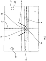
- the axis of symmetry of the guide cone 31 is to be oriented in accordance with the angle ⁇ of a displacement vector, as shown schematically in FIG Fig. 8 is shown.
- Fig. 8 is a view from behind of the clutch plate 4 with its Einfahrschlitz 5 toward the cab rear wall 33 shown.
- the optimal camera position 34 with corresponding alignment of the optical axis is in the middle of the Einfahrschlitzes 5 at the top of the coupling plate 4.
- This angle ⁇ is calculated by the following relationship.
- a arctan ⁇ ⁇ z ⁇ ⁇ y
- the axis of symmetry of a relevant here traffic cone 31 is to be aligned according to the angle ⁇ of the displacement vector 36.
Landscapes
- Engineering & Computer Science (AREA)
- Mechanical Engineering (AREA)
- Multimedia (AREA)
- Transportation (AREA)
- Chemical & Material Sciences (AREA)
- Combustion & Propulsion (AREA)
- Traffic Control Systems (AREA)
Claims (16)
- Système d'assistance au conducteur pour un attelage de véhicule utilitaire,
dans lequel l'attelage de véhicule utilitaire est réalisé sous la forme d'un semi-remorque (1) comprenant un véhicule tracteur (2) et une remorque (3), dans lequel il est prévu un dispositif d'attelage qui comporte, sur la remorque (3), du côté du véhicule tracteur, une pièce de réception d'attelage verrouillable (4 ; 37) et un élément d'attelage (13 ; 44) associé, rétractable dans la pièce de réception d'attelage (4 ; 37), et dans lequel il est prévu du côté du véhicule tracteur, dans le champ de vision d'un conducteur, un dispositif de caméra de recul comportant une caméra vidéo (14) et un écran associé (15) pour une image vidéo (17), dans lequel un repère de guidage visible par le conducteur est incrusté dans l'image vidéo (17) en tant que moyen de repérage de direction qui visualise la zone de rétraction de l'élément d'attelage (13 ; 44) sur la pièce de réception d'attelage (4 ; 37),
caractérisé en ce que la caméra vidéo (14) est associée à la pièce de réception d'attelage (4 ; 37) de manière à ce que la zone de la pièce de réception d'attelage (4 ; 37) ainsi qu'un environnement arrière comportant l'élément d'attelage (13 ; 44) puissent être détectés et représentés sur l'image vidéo (17). - Système d'assistance au conducteur selon la revendication 1,
caractérisé en ce que le repère de guidage présent dans l'image vidéo (17) comporte ou est une ligne de guidage verticale (21) qui passe à travers une fente de rétraction (5), ouverte vers l'arrière dans la direction de l'axe longitudinal du véhicule, d'une plaque d'attelage (4) du véhicule tracteur (2) du semi-remorque (1), en particulier pour un alignement horizontal précis d'un boulon d'attelage (13) avec la plaque de semi-remorque (24) d'une remorque (3). - Système d'assistance au conducteur selon la revendication 2,
caractérisé en ce que le repère de guidage présent dans l'image vidéo (17) est réalisé sous la forme d'un réticule cible (20) qui est constitué par la ligne verticale (21) et par une ligne d'assistance en hauteur horizontale (22), qui permet de visualiser une position en hauteur sur le véhicule tracteur (2), qui est pertinente pour le processus d'attelage. - Système d'assistance au conducteur selon la revendication 3,
caractérisé en ce que la ligne d'assistance en hauteur horizontale dans le véhicule tracteur (2) du semi-remorque (1) visualise la position en hauteur de la face supérieure d'une plaque d'attelage (4), de préférence d'une plaque d'attelage (4) pouvant basculer autour d'un axe transversal (axe y) du véhicule au point d'attelage et/ou au centre d'un verrou d'attelage (6) d'une plaque d'attelage (4), en particulier pour assister le conducteur dans le réglage en hauteur verticale entre la plaque d'attelage (4) et la plaque de semi-remorque (24) pendant le processus d'attelage, ou en ce que la ligne d'assistance en hauteur horizontale (22) dans le véhicule tracteur d'un train articulé visualise la hauteur d'une mâchoire (38) d'un attelage à mâchoire (37). - Système d'assistance au conducteur selon la revendication 3 ou 4,
caractérisé en ce qu'il est prévu un dispositif de traitement d'image, en particulier un dispositif de traitement d'image comportant au moins un algorithme de traitement d'image, au moyen duquel il est possible de détecter, en particulier automatiquement, un bord inférieur (19) avant, dans la direction de déplacement, de la remorque (3) du semi-remorque (1), et/ou les composants de la remorque (3) du semi-remorque (1) qui permettent, pendant le processus d'attelage, d'estimer la hauteur de la position relative entre la plaque d'attelage (4) et la plaque de semi-remorque (24) et/ou un boulon d'attelage (13). - Système d'assistance au conducteur selon l'une des revendications précédentes, caractérisé en ce qu'il est prévu un dispositif permettant de lever/abaisser le véhicule tracteur (2) et/ou la remorque (3), au moyen duquel il est possible d'effectuer, en particulier automatiquement, une compensation de hauteur pendant le processus d'attelage, par évaluation de données d'image indiquant la position relative entre la pièce de réception d'attelage (4 ; 37) et l'élément d'attelage (13 ; 44).
- Système d'assistance au conducteur selon l'une des revendications précédentes, caractérisé en ce qu'il est prévu un dispositif pour déterminer et/ou estimer la distance horizontale lors du rapprochement entre la pièce de réception d'attelage (4 ; 38) et l'élément d'attelage (13 ; 44), en particulier pendant le rapprochement entre une plaque d'attelage (4) et un boulon d'attelage (13) du semi-remorque (1), au moyen duquel au moins un repère auxiliaire ou une forme virtuelle constituant un élément d'un repère de guidage indiquant la distance peut être incrusté dans l'image vidéo en tant qu'élément d'un repère de guidage.
- Système d'assistance au conducteur selon la revendication 7, caractérisé en ce que ledit au moins un repère auxiliaire est une aide à la détermination de distance comprenant au moins une ligne de guidage (25) incrustée dans l'image vidéo, qui, à des distances définies entre le véhicule tracteur (2) et la remorque (3), coïncide avec au moins un bord défini, en particulier avec au moins un bord extérieur associé, de la remorque (3), et/ou en ce que ledit au moins un repère auxiliaire est constitué par au moins une forme virtuelle (23) incrustée, qui correspond en taille à au moins un composant défini (13 ; 26, 27) de la remorque (3) et/ou à sa forme à une distance définie entre le véhicule tracteur (2) et la remorque (3).
- Système d'assistance au conducteur selon la revendication 7 ou la revendication 8, caractérisé en ce que le dispositif de détermination et/ou d'estimation de la distance horizontale permet, au moyen d'un dispositif de traitement d'image, de détecter au moins un composant normalisé (13) de la remorque (3), qui est représenté dans l'image vidéo (17), et de comparer la taille effectivement détectée à la taille réelle connue et stockée, dans lequel il est de préférence fait en sorte que la distance réelle puisse être déterminée au moyen d'un dispositif d'évaluation à partir de la comparaison de taille actuelle et puisse être présentée graphiquement et/ou numériquement au conducteur.
- Système d'assistance au conducteur selon l'une des revendications précédentes, caractérisé en ce qu'il est prévu un dispositif d'adaptation au moyen duquel au moins certains des éléments formant le repère de guidage, en particulier des lignes de guidage (21, 22) et/ou des repères auxiliaires (23) et/ou un réticule cible (20), peuvent être adaptés automatiquement ou manuellement en couleur et/ou en transparence et/ou en forme (28), de manière stationnaire ou dynamique, en fonction de la progressions du processus d'attelage, aux conditions de visualisation et/ou aux plages de tolérance et/ou aux plages physiquement possibles.
- Système d'assistance au conducteur selon l'une des revendications précédentes, caractérisé en ce qu'il est prévu un dispositif de zoom au moyen duquel la taille de la section d'image affichée dans ou comme image vidéo peut être modifiée manuellement ou automatiquement, en particulier en fonction du processus d'attelage.
- Système d'assistance au conducteur selon l'une des revendications précédentes, caractérisé en ce que la caméra vidéo (14) est positionnée sur le véhicule tracteur (2) du semi-remorque (1) de telle sorte que son axe optique (45) s'étende au centre longitudinal du véhicule et horizontalement à la hauteur du bord supérieur de la plaque d'attelage (4), ou en ce que la caméra vidéo (14) du véhicule tracteur (2) présente sur un train articulé est orientée suivant un axe optique au centre longitudinal du véhicule.
- Système d'assistance au conducteur selon l'une des revendications précédentes, caractérisé en ce que la caméra vidéo (14) est positionnée sur le véhicule tracteur (2) du semi-remorque (1) de telle sorte que sa position dans la direction y et/ou z s'écarte d'un axe optique horizontal (45) passant par le centre longitudinal du véhicule à la hauteur du bord supérieur de la pièce de réception d'attelage (4), et
en ce que, dans ce cas, en plus d'un réticule cible (20) constitué par une ligne de guidage verticale (21) et une ligne de hauteur horizontale (22), un cône de guidage (31), dont l'ouverture de cône de guidage et l'axe de cône sont orientés dans la direction dudit écart, est en outre incrusté en tant que repère de guidage, dans lequel le cône de guidage (31) est le cas échéant aplati dans la zone du réticule cible (20) par la base (32) du cône et la largeur de la base (32) du cône correspond ainsi à la plage de tolérance latérale du point d'attelage. - Système d'assistance au conducteur selon la revendication 13, caractérisé en ce que la caméra vidéo (14) est fixée à la paroi arrière (33) de la cabine du conducteur ou de manière fixe au châssis du véhicule, en particulier sur un rail (16) se trouvant à cet endroit et s'étendant dans la direction z.
- Procédé de réalisation d'un processus d'attelage pour un attelage de véhicule utilitaire comportant un système d'assistance au conducteur,
dans lequel l'attelage de véhicule utilitaire est réalisé sous la forme d'un semi-remorque (1) comprenant un véhicule tracteur (2) et une remorque (3), dans lequel il est prévu un dispositif d'attelage qui comporte, sur la remorque (3), une pièce de réception d'attelage verrouillable (4 ; 37) du côté du véhicule tracteur et un élément d'attelage associé (13 ; 44) rétractable dans la pièce de réception d'attelage (4 ; 37), et dans lequel il est prévu du côté du véhicule tracteur, dans le champ de vision d'un conducteur, un dispositif de caméra de recul comportant une caméra vidéo (14) et un écran associé (15) pour une image vidéo (17),
caractérisé en ce que la caméra vidéo (14) est associée à la pièce de réception d'attelage (4 ; 37) de manière à ce qu'elle détecte la zone de la pièce de réception d'attelage (4 ; 37) ainsi qu'un environnement arrière comportant l'élément d'attelage (13 ; 44) et la représente dans l'image vidéo (17),
et en ce qu'au moins un repère de guidage visible par le conducteur est incrusté dans l'image vidéo (17) en tant que moyen de repérage de direction qui visualise la zone de rétraction de l'élément d'attelage (13 ; 44) sur la pièce de réception d'attelage (4 ; 37). - Véhicule utilitaire équipé d'un système d'assistance au conducteur selon l'une des revendications 1 à 14 précédentes, destiné à mettre en oeuvre le procédé selon la revendication 15.
Applications Claiming Priority (1)
| Application Number | Priority Date | Filing Date | Title |
|---|---|---|---|
| DE102014012330.8A DE102014012330A1 (de) | 2014-08-20 | 2014-08-20 | Fahrerassistenzsystem für ein Nutzfahrzeuggespann sowie Verfahren zur Durchführung eines Ankuppelvorgangs |
Publications (2)
| Publication Number | Publication Date |
|---|---|
| EP2987663A1 EP2987663A1 (fr) | 2016-02-24 |
| EP2987663B1 true EP2987663B1 (fr) | 2019-05-08 |
Family
ID=52814774
Family Applications (1)
| Application Number | Title | Priority Date | Filing Date |
|---|---|---|---|
| EP15000914.0A Active EP2987663B1 (fr) | 2014-08-20 | 2015-03-28 | Système d'assistance au conducteur pour un attelage de véhicule utilitaire et procédé d'exécution d'un processus d'attelage |
Country Status (2)
| Country | Link |
|---|---|
| EP (1) | EP2987663B1 (fr) |
| DE (1) | DE102014012330A1 (fr) |
Families Citing this family (19)
| Publication number | Priority date | Publication date | Assignee | Title |
|---|---|---|---|---|
| DE102016011324A1 (de) | 2016-09-21 | 2018-03-22 | Wabco Gmbh | Verfahren zur Steuerung eines Zugfahrzeugs bei dessen Heranfahren und Ankuppeln an ein Anhängerfahrzeug |
| WO2018162031A1 (fr) * | 2017-03-06 | 2018-09-13 | Volvo Truck Corporation | Procédés d'aide au désaccouplement/à l'accouplement automatique d'une remorque |
| DE102017119969B4 (de) * | 2017-08-31 | 2023-01-05 | Saf-Holland Gmbh | Anhänger mit einer Anhänger-Steuervorrichtung, Ankupplungssystem und Verfahren zur Durchführung eines Kupplungsprozesses |
| DE102017119968B4 (de) | 2017-08-31 | 2020-06-18 | Saf-Holland Gmbh | Anhänger und System zur Identifikation eines Anhängers und zur Unterstützung eines Ankupplungsprozesses an eine Zugmaschine |
| DE102017221458B3 (de) | 2017-11-29 | 2019-02-07 | Volkswagen Aktiengesellschaft | Verfahren zum Betreiben einer Bedienvorrichtung für ein Kraftfahrzeug, um einen Fahrer beim Ankuppeln des Kraftfahrzeugs an einen Anhänger zu unterstützen, sowie Bedienvorrichtung und Kraftfahrzeug |
| DE102018204442B4 (de) * | 2018-03-22 | 2021-05-27 | Zf Friedrichshafen Ag | Anhänger und Verfahren und Steuergerät zum Bestimmen einer Orientierung eines Anhängers |
| DE102018210361B4 (de) * | 2018-06-26 | 2020-07-23 | Zf Friedrichshafen Ag | Verfahren zum Ermitteln einer Relativpose zwischen einem Fahrzeug und einem Zielobjekt |
| DE102018210356A1 (de) * | 2018-06-26 | 2020-01-02 | Zf Friedrichshafen Ag | Verfahren zur Unterstützung eines Fahrers eines Nutzfahrzeugs bei einem Unterfahren einer Wechselbrücke und Fahrerassistenzsystem |
| DE102018214973A1 (de) | 2018-09-04 | 2020-03-05 | Volkswagen Aktiengesellschaft | Verfahren und System zum automatischen Erkennen eines Ankuppelmanövers eines Kraftfahrzeugs an einen Anhänger |
| DE102019008918B4 (de) * | 2019-12-20 | 2023-03-30 | Jost-Werke Deutschland Gmbh | Sattelkupplung mit einer Kupplungsplatte und einer Kamera |
| DE102020003141A1 (de) * | 2020-05-26 | 2021-12-02 | Jost-Werke Deutschland Gmbh | Fahrerassistenzsystem und Verfahren zum Ankuppeln eines Anhängers an ein Zugfahrzeug |
| CN114425930A (zh) * | 2022-02-24 | 2022-05-03 | 一汽解放汽车有限公司 | 挂车辅助装置 |
| DE102022003183A1 (de) * | 2022-08-31 | 2024-02-29 | Jost-Werke Deutschland Gmbh | Kupplungsvorrichtung für ein Zugfahrzeug mit einem daran angebrachten Objekterkennungsmittel |
| DE102022003318B4 (de) | 2022-09-09 | 2026-05-07 | Jost-Werke Deutschland Gmbh | Ausrichtsystem zur annäherung eines fahrzeugs an ein hierzu räumlich beabstandetes zielobjekt |
| DE102022123359A1 (de) | 2022-09-13 | 2024-03-14 | Jost-Werke Deutschland Gmbh | Verfahren zum Kuppeln einer Sattelzugmaschine mit einem Sattelauflieger sowie Sattelzug mit einer Sattelzugmaschine und einem Sattelauflieger |
| CN115520290B (zh) * | 2022-10-20 | 2025-03-28 | 龙岩学院 | 一种半挂汽车列车辅助对接用连接装置及其使用方法 |
| CN115742957A (zh) * | 2022-11-30 | 2023-03-07 | 东土华盛科技有限公司 | 控制车辆对接的方法及装置、车辆 |
| DE102023107289A1 (de) * | 2023-03-23 | 2024-09-26 | Zf Cv Systems Global Gmbh | Verfahren zum Ankoppeln eines Aufliegers an ein Zugfahrzeug, Ankoppel-Anordnung und Fahrzeug |
| DE102023107288A1 (de) * | 2023-03-23 | 2024-09-26 | Zf Cv Systems Global Gmbh | Verfahren zum Ankoppeln eines Aufliegers an ein Zugfahrzeug, Ankoppel-Anordnung und Fahrzeug |
Citations (2)
| Publication number | Priority date | Publication date | Assignee | Title |
|---|---|---|---|---|
| DE102004043761A1 (de) * | 2004-09-10 | 2006-03-16 | Daimlerchrysler Ag | Verfahren und Vorrichtung zum Überwachen einer Anhängerkupplung |
| EP2921350A2 (fr) * | 2014-03-20 | 2015-09-23 | MAN Truck & Bus AG | Système d'assistance à la conduite basé sur une caméra d'un véhicule tracteur, en particulier d'un véhicule tracteur d'un attelage de véhicule utilitaire |
Family Cites Families (3)
| Publication number | Priority date | Publication date | Assignee | Title |
|---|---|---|---|---|
| DE102004029130A1 (de) * | 2004-06-17 | 2005-12-29 | Daimlerchrysler Ag | Verfahren zur Ankupplung eines Anhängers an ein Kraftfahrzeug |
| DE102004029129B4 (de) * | 2004-06-17 | 2008-08-28 | Daimler Ag | Verfahren und Vorrichtung zur Ankupplung eines Anhängers an ein Kraftfahrzeug |
| US20140151979A1 (en) * | 2012-12-03 | 2014-06-05 | Fontaine Fifth Wheel | Fifth Wheel Backup Camera System and Method |
-
2014
- 2014-08-20 DE DE102014012330.8A patent/DE102014012330A1/de not_active Withdrawn
-
2015
- 2015-03-28 EP EP15000914.0A patent/EP2987663B1/fr active Active
Patent Citations (2)
| Publication number | Priority date | Publication date | Assignee | Title |
|---|---|---|---|---|
| DE102004043761A1 (de) * | 2004-09-10 | 2006-03-16 | Daimlerchrysler Ag | Verfahren und Vorrichtung zum Überwachen einer Anhängerkupplung |
| EP2921350A2 (fr) * | 2014-03-20 | 2015-09-23 | MAN Truck & Bus AG | Système d'assistance à la conduite basé sur une caméra d'un véhicule tracteur, en particulier d'un véhicule tracteur d'un attelage de véhicule utilitaire |
Also Published As
| Publication number | Publication date |
|---|---|
| DE102014012330A1 (de) | 2016-02-25 |
| EP2987663A1 (fr) | 2016-02-24 |
Similar Documents
| Publication | Publication Date | Title |
|---|---|---|
| EP2987663B1 (fr) | Système d'assistance au conducteur pour un attelage de véhicule utilitaire et procédé d'exécution d'un processus d'attelage | |
| DE112012000466B4 (de) | System und Verfahren zum Manövrieren eines Fahrzeug-Anhänger-Gespanns bei Rückwärtsfahrt | |
| EP3219533B1 (fr) | Système de vision pour un véhicule, notamment pour un véhicule utilitaire | |
| EP3024700B1 (fr) | Procédé et dispositif permettant de reproduire une zone latérale et/ou arrière environnant un véhicule | |
| EP3743312B1 (fr) | Méthode et dispositif pour opérer un système de vidéo surveillance pour un véhicule motorisé | |
| DE10109350B4 (de) | Unterstützungseinrichtung zum Rückwärtseinparken eines Fahrzeugs in Reihe | |
| DE102016011324A1 (de) | Verfahren zur Steuerung eines Zugfahrzeugs bei dessen Heranfahren und Ankuppeln an ein Anhängerfahrzeug | |
| DE102018206494A1 (de) | Verfahren zum Betreiben eines Anhängerrangierassistenzsystems eines Kraftfahrzeugs und Anhängerrangierassistenzsystem für ein Kraftfahrzeug | |
| DE102016109954A1 (de) | Verfahren zum Unterstützen eines Fahrers eines Gespanns beim Rangieren des Gespanns, Fahrerassistenzsystem sowie Kraftfahrzeug | |
| DE102014204872B4 (de) | Verfahren und Anzeigesystem zum Anzeigen von Umgebungsinformationen eines Fahrzeugs | |
| DE102009032024A1 (de) | Verfahren zum Bestimmen einer Position eines an einem Fahrzeug angehängten Anhängers relativ zum Fahrzeug sowie Fahrerassistenzsystem für ein Fahrzeug | |
| DE102019117132A1 (de) | System und verfahren zur erkennung von und reaktion auf störung zwischen anhängerverbindungsstück und anhängerkupplungskugel | |
| EP3915838B1 (fr) | Système d'aide à la conduite et procédé d'accouplement d'une remorque à un véhicule tracté | |
| EP3012154A1 (fr) | Procede et dispositif d'assistance d'un conducteur d'un attelage, notamment d'un attelage de vehicule utilitaire | |
| DE102016115132A1 (de) | Unterstützung eines Fahrers eines Kraftfahrzeugs mit einem angehängten Anhänger beim Einparken durch virtuelle Sensoren | |
| DE102020107023A1 (de) | System und verfahren zur anhängerausrichtung | |
| DE102014218995A1 (de) | Verfahren und Vorrichtung zur Bird-View-Darstellung eines Fahrzeuggespanns sowie nachrüstbare Kamera | |
| EP3476696B1 (fr) | Procédé de détermination des limites d'un objet dans une zone externe d'un véhicule automobile ainsi que dispositif de commande et véhicule automobile | |
| DE102022003318B4 (de) | Ausrichtsystem zur annäherung eines fahrzeugs an ein hierzu räumlich beabstandetes zielobjekt | |
| EP4103413A1 (fr) | Procédé et système de détermination d'une orientation d'une remorque par rapport à un véhicule tracteur | |
| WO2024121792A1 (fr) | Système de caméra pour l'attelage précis d'un véhicule remorque à un véhicule tracteur | |
| DE102016117401B4 (de) | Verfahren und Vorrichtung zum Abbilden eines Anhängers mit Begrenzungsmarkierungen | |
| DE102024001840A1 (de) | Sicherheitssystem für ein treffsicheres Ankuppeln eines Anhängerfahrzeugs an ein Zugfahrzeug | |
| DE102016110305B4 (de) | Verfahren zum Unterstützen eines Fahrers eines Kraftfahrzeugs beim Rangieren des Kraftfahrzeugs mit einem Anhänger, Fahrerassistenzsystem sowie Kraftfahrzeug | |
| DE102018010096A1 (de) | Verfahren zur Visualisierung einer Anhängekupplung und eines Anhängerzugmauls |
Legal Events
| Date | Code | Title | Description |
|---|---|---|---|
| PUAI | Public reference made under article 153(3) epc to a published international application that has entered the european phase |
Free format text: ORIGINAL CODE: 0009012 |
|
| AK | Designated contracting states |
Kind code of ref document: A1 Designated state(s): AL AT BE BG CH CY CZ DE DK EE ES FI FR GB GR HR HU IE IS IT LI LT LU LV MC MK MT NL NO PL PT RO RS SE SI SK SM TR |
|
| AX | Request for extension of the european patent |
Extension state: BA ME |
|
| 17P | Request for examination filed |
Effective date: 20160822 |
|
| STAA | Information on the status of an ep patent application or granted ep patent |
Free format text: STATUS: EXAMINATION IS IN PROGRESS |
|
| 17Q | First examination report despatched |
Effective date: 20180130 |
|
| GRAP | Despatch of communication of intention to grant a patent |
Free format text: ORIGINAL CODE: EPIDOSNIGR1 |
|
| STAA | Information on the status of an ep patent application or granted ep patent |
Free format text: STATUS: GRANT OF PATENT IS INTENDED |
|
| INTG | Intention to grant announced |
Effective date: 20181105 |
|
| GRAS | Grant fee paid |
Free format text: ORIGINAL CODE: EPIDOSNIGR3 |
|
| GRAA | (expected) grant |
Free format text: ORIGINAL CODE: 0009210 |
|
| STAA | Information on the status of an ep patent application or granted ep patent |
Free format text: STATUS: THE PATENT HAS BEEN GRANTED |
|
| AK | Designated contracting states |
Kind code of ref document: B1 Designated state(s): AL AT BE BG CH CY CZ DE DK EE ES FI FR GB GR HR HU IE IS IT LI LT LU LV MC MK MT NL NO PL PT RO RS SE SI SK SM TR |
|
| REG | Reference to a national code |
Ref country code: GB Ref legal event code: FG4D Free format text: NOT ENGLISH |
|
| REG | Reference to a national code |
Ref country code: CH Ref legal event code: EP Ref country code: AT Ref legal event code: REF Ref document number: 1129577 Country of ref document: AT Kind code of ref document: T Effective date: 20190515 |
|
| REG | Reference to a national code |
Ref country code: DE Ref legal event code: R096 Ref document number: 502015008938 Country of ref document: DE |
|
| REG | Reference to a national code |
Ref country code: IE Ref legal event code: FG4D Free format text: LANGUAGE OF EP DOCUMENT: GERMAN |
|
| REG | Reference to a national code |
Ref country code: NL Ref legal event code: FP |
|
| RAP2 | Party data changed (patent owner data changed or rights of a patent transferred) |
Owner name: MAN TRUCK & BUS SE |
|
| REG | Reference to a national code |
Ref country code: SE Ref legal event code: TRGR |
|
| REG | Reference to a national code |
Ref country code: LT Ref legal event code: MG4D Ref country code: DE Ref legal event code: R081 Ref document number: 502015008938 Country of ref document: DE Owner name: MAN TRUCK & BUS SE, DE Free format text: FORMER OWNER: MAN TRUCK & BUS AG, 80995 MUENCHEN, DE |
|
| PG25 | Lapsed in a contracting state [announced via postgrant information from national office to epo] |
Ref country code: AL Free format text: LAPSE BECAUSE OF FAILURE TO SUBMIT A TRANSLATION OF THE DESCRIPTION OR TO PAY THE FEE WITHIN THE PRESCRIBED TIME-LIMIT Effective date: 20190508 Ref country code: ES Free format text: LAPSE BECAUSE OF FAILURE TO SUBMIT A TRANSLATION OF THE DESCRIPTION OR TO PAY THE FEE WITHIN THE PRESCRIBED TIME-LIMIT Effective date: 20190508 Ref country code: LT Free format text: LAPSE BECAUSE OF FAILURE TO SUBMIT A TRANSLATION OF THE DESCRIPTION OR TO PAY THE FEE WITHIN THE PRESCRIBED TIME-LIMIT Effective date: 20190508 Ref country code: FI Free format text: LAPSE BECAUSE OF FAILURE TO SUBMIT A TRANSLATION OF THE DESCRIPTION OR TO PAY THE FEE WITHIN THE PRESCRIBED TIME-LIMIT Effective date: 20190508 Ref country code: PT Free format text: LAPSE BECAUSE OF FAILURE TO SUBMIT A TRANSLATION OF THE DESCRIPTION OR TO PAY THE FEE WITHIN THE PRESCRIBED TIME-LIMIT Effective date: 20190908 Ref country code: NO Free format text: LAPSE BECAUSE OF FAILURE TO SUBMIT A TRANSLATION OF THE DESCRIPTION OR TO PAY THE FEE WITHIN THE PRESCRIBED TIME-LIMIT Effective date: 20190808 Ref country code: HR Free format text: LAPSE BECAUSE OF FAILURE TO SUBMIT A TRANSLATION OF THE DESCRIPTION OR TO PAY THE FEE WITHIN THE PRESCRIBED TIME-LIMIT Effective date: 20190508 |
|
| PG25 | Lapsed in a contracting state [announced via postgrant information from national office to epo] |
Ref country code: LV Free format text: LAPSE BECAUSE OF FAILURE TO SUBMIT A TRANSLATION OF THE DESCRIPTION OR TO PAY THE FEE WITHIN THE PRESCRIBED TIME-LIMIT Effective date: 20190508 Ref country code: GR Free format text: LAPSE BECAUSE OF FAILURE TO SUBMIT A TRANSLATION OF THE DESCRIPTION OR TO PAY THE FEE WITHIN THE PRESCRIBED TIME-LIMIT Effective date: 20190809 Ref country code: BG Free format text: LAPSE BECAUSE OF FAILURE TO SUBMIT A TRANSLATION OF THE DESCRIPTION OR TO PAY THE FEE WITHIN THE PRESCRIBED TIME-LIMIT Effective date: 20190808 Ref country code: RS Free format text: LAPSE BECAUSE OF FAILURE TO SUBMIT A TRANSLATION OF THE DESCRIPTION OR TO PAY THE FEE WITHIN THE PRESCRIBED TIME-LIMIT Effective date: 20190508 |
|
| PG25 | Lapsed in a contracting state [announced via postgrant information from national office to epo] |
Ref country code: RO Free format text: LAPSE BECAUSE OF FAILURE TO SUBMIT A TRANSLATION OF THE DESCRIPTION OR TO PAY THE FEE WITHIN THE PRESCRIBED TIME-LIMIT Effective date: 20190508 Ref country code: CZ Free format text: LAPSE BECAUSE OF FAILURE TO SUBMIT A TRANSLATION OF THE DESCRIPTION OR TO PAY THE FEE WITHIN THE PRESCRIBED TIME-LIMIT Effective date: 20190508 Ref country code: EE Free format text: LAPSE BECAUSE OF FAILURE TO SUBMIT A TRANSLATION OF THE DESCRIPTION OR TO PAY THE FEE WITHIN THE PRESCRIBED TIME-LIMIT Effective date: 20190508 Ref country code: DK Free format text: LAPSE BECAUSE OF FAILURE TO SUBMIT A TRANSLATION OF THE DESCRIPTION OR TO PAY THE FEE WITHIN THE PRESCRIBED TIME-LIMIT Effective date: 20190508 Ref country code: SK Free format text: LAPSE BECAUSE OF FAILURE TO SUBMIT A TRANSLATION OF THE DESCRIPTION OR TO PAY THE FEE WITHIN THE PRESCRIBED TIME-LIMIT Effective date: 20190508 |
|
| REG | Reference to a national code |
Ref country code: DE Ref legal event code: R097 Ref document number: 502015008938 Country of ref document: DE |
|
| PG25 | Lapsed in a contracting state [announced via postgrant information from national office to epo] |
Ref country code: SM Free format text: LAPSE BECAUSE OF FAILURE TO SUBMIT A TRANSLATION OF THE DESCRIPTION OR TO PAY THE FEE WITHIN THE PRESCRIBED TIME-LIMIT Effective date: 20190508 |
|
| PLBE | No opposition filed within time limit |
Free format text: ORIGINAL CODE: 0009261 |
|
| STAA | Information on the status of an ep patent application or granted ep patent |
Free format text: STATUS: NO OPPOSITION FILED WITHIN TIME LIMIT |
|
| PG25 | Lapsed in a contracting state [announced via postgrant information from national office to epo] |
Ref country code: TR Free format text: LAPSE BECAUSE OF FAILURE TO SUBMIT A TRANSLATION OF THE DESCRIPTION OR TO PAY THE FEE WITHIN THE PRESCRIBED TIME-LIMIT Effective date: 20190508 |
|
| 26N | No opposition filed |
Effective date: 20200211 |
|
| PG25 | Lapsed in a contracting state [announced via postgrant information from national office to epo] |
Ref country code: PL Free format text: LAPSE BECAUSE OF FAILURE TO SUBMIT A TRANSLATION OF THE DESCRIPTION OR TO PAY THE FEE WITHIN THE PRESCRIBED TIME-LIMIT Effective date: 20190508 |
|
| PG25 | Lapsed in a contracting state [announced via postgrant information from national office to epo] |
Ref country code: SI Free format text: LAPSE BECAUSE OF FAILURE TO SUBMIT A TRANSLATION OF THE DESCRIPTION OR TO PAY THE FEE WITHIN THE PRESCRIBED TIME-LIMIT Effective date: 20190508 |
|
| PG25 | Lapsed in a contracting state [announced via postgrant information from national office to epo] |
Ref country code: MC Free format text: LAPSE BECAUSE OF FAILURE TO SUBMIT A TRANSLATION OF THE DESCRIPTION OR TO PAY THE FEE WITHIN THE PRESCRIBED TIME-LIMIT Effective date: 20190508 |
|
| REG | Reference to a national code |
Ref country code: CH Ref legal event code: PL |
|
| REG | Reference to a national code |
Ref country code: BE Ref legal event code: MM Effective date: 20200331 |
|
| PG25 | Lapsed in a contracting state [announced via postgrant information from national office to epo] |
Ref country code: LU Free format text: LAPSE BECAUSE OF NON-PAYMENT OF DUE FEES Effective date: 20200328 |
|
| PG25 | Lapsed in a contracting state [announced via postgrant information from national office to epo] |
Ref country code: IE Free format text: LAPSE BECAUSE OF NON-PAYMENT OF DUE FEES Effective date: 20200328 Ref country code: LI Free format text: LAPSE BECAUSE OF NON-PAYMENT OF DUE FEES Effective date: 20200331 Ref country code: CH Free format text: LAPSE BECAUSE OF NON-PAYMENT OF DUE FEES Effective date: 20200331 |
|
| PG25 | Lapsed in a contracting state [announced via postgrant information from national office to epo] |
Ref country code: BE Free format text: LAPSE BECAUSE OF NON-PAYMENT OF DUE FEES Effective date: 20200331 |
|
| GBPC | Gb: european patent ceased through non-payment of renewal fee |
Effective date: 20200328 |
|
| PG25 | Lapsed in a contracting state [announced via postgrant information from national office to epo] |
Ref country code: GB Free format text: LAPSE BECAUSE OF NON-PAYMENT OF DUE FEES Effective date: 20200328 |
|
| REG | Reference to a national code |
Ref country code: AT Ref legal event code: MM01 Ref document number: 1129577 Country of ref document: AT Kind code of ref document: T Effective date: 20200328 |
|
| PG25 | Lapsed in a contracting state [announced via postgrant information from national office to epo] |
Ref country code: AT Free format text: LAPSE BECAUSE OF NON-PAYMENT OF DUE FEES Effective date: 20200328 |
|
| PG25 | Lapsed in a contracting state [announced via postgrant information from national office to epo] |
Ref country code: MT Free format text: LAPSE BECAUSE OF FAILURE TO SUBMIT A TRANSLATION OF THE DESCRIPTION OR TO PAY THE FEE WITHIN THE PRESCRIBED TIME-LIMIT Effective date: 20190508 Ref country code: CY Free format text: LAPSE BECAUSE OF FAILURE TO SUBMIT A TRANSLATION OF THE DESCRIPTION OR TO PAY THE FEE WITHIN THE PRESCRIBED TIME-LIMIT Effective date: 20190508 |
|
| PG25 | Lapsed in a contracting state [announced via postgrant information from national office to epo] |
Ref country code: MK Free format text: LAPSE BECAUSE OF FAILURE TO SUBMIT A TRANSLATION OF THE DESCRIPTION OR TO PAY THE FEE WITHIN THE PRESCRIBED TIME-LIMIT Effective date: 20190508 Ref country code: IS Free format text: LAPSE BECAUSE OF FAILURE TO SUBMIT A TRANSLATION OF THE DESCRIPTION OR TO PAY THE FEE WITHIN THE PRESCRIBED TIME-LIMIT Effective date: 20190908 |
|
| PGFP | Annual fee paid to national office [announced via postgrant information from national office to epo] |
Ref country code: SE Payment date: 20260323 Year of fee payment: 12 |
|
| PGFP | Annual fee paid to national office [announced via postgrant information from national office to epo] |
Ref country code: DE Payment date: 20260320 Year of fee payment: 12 |
|
| PGFP | Annual fee paid to national office [announced via postgrant information from national office to epo] |
Ref country code: IT Payment date: 20260320 Year of fee payment: 12 |
|
| PGFP | Annual fee paid to national office [announced via postgrant information from national office to epo] |
Ref country code: NL Payment date: 20260323 Year of fee payment: 12 |
|
| PGFP | Annual fee paid to national office [announced via postgrant information from national office to epo] |
Ref country code: FR Payment date: 20260323 Year of fee payment: 12 |