EP3476696B1 - Procédé de détermination des limites d'un objet dans une zone externe d'un véhicule automobile ainsi que dispositif de commande et véhicule automobile - Google Patents
Procédé de détermination des limites d'un objet dans une zone externe d'un véhicule automobile ainsi que dispositif de commande et véhicule automobile Download PDFInfo
- Publication number
- EP3476696B1 EP3476696B1 EP18194311.9A EP18194311A EP3476696B1 EP 3476696 B1 EP3476696 B1 EP 3476696B1 EP 18194311 A EP18194311 A EP 18194311A EP 3476696 B1 EP3476696 B1 EP 3476696B1
- Authority
- EP
- European Patent Office
- Prior art keywords
- motor vehicle
- image
- profile
- scanning line
- control device
- Prior art date
- Legal status (The legal status is an assumption and is not a legal conclusion. Google has not performed a legal analysis and makes no representation as to the accuracy of the status listed.)
- Active
Links
Images


Classifications
-
- B—PERFORMING OPERATIONS; TRANSPORTING
- B60—VEHICLES IN GENERAL
- B60D—VEHICLE CONNECTIONS
- B60D1/00—Traction couplings; Hitches; Draw-gear; Towing devices
- B60D1/24—Traction couplings; Hitches; Draw-gear; Towing devices characterised by arrangements for particular functions
- B60D1/30—Traction couplings; Hitches; Draw-gear; Towing devices characterised by arrangements for particular functions for sway control ; Sway alarm means
-
- B—PERFORMING OPERATIONS; TRANSPORTING
- B60—VEHICLES IN GENERAL
- B60D—VEHICLE CONNECTIONS
- B60D1/00—Traction couplings; Hitches; Draw-gear; Towing devices
- B60D1/58—Auxiliary devices
- B60D1/62—Auxiliary devices involving supply lines, electric circuits or the like
-
- B—PERFORMING OPERATIONS; TRANSPORTING
- B62—LAND VEHICLES FOR TRAVELLING OTHERWISE THAN ON RAILS
- B62D—MOTOR VEHICLES; TRAILERS
- B62D13/00—Steering specially adapted for trailers
- B62D13/06—Steering specially adapted for trailers for backing a normally drawn trailer
-
- G—PHYSICS
- G06—COMPUTING OR CALCULATING; COUNTING
- G06F—ELECTRIC DIGITAL DATA PROCESSING
- G06F16/00—Information retrieval; Database structures therefor; File system structures therefor
- G06F16/50—Information retrieval; Database structures therefor; File system structures therefor of still image data
- G06F16/58—Retrieval characterised by using metadata, e.g. metadata not derived from the content or metadata generated manually
- G06F16/583—Retrieval characterised by using metadata, e.g. metadata not derived from the content or metadata generated manually using metadata automatically derived from the content
- G06F16/5854—Retrieval characterised by using metadata, e.g. metadata not derived from the content or metadata generated manually using metadata automatically derived from the content using shape and object relationship
-
- G—PHYSICS
- G06—COMPUTING OR CALCULATING; COUNTING
- G06V—IMAGE OR VIDEO RECOGNITION OR UNDERSTANDING
- G06V20/00—Scenes; Scene-specific elements
- G06V20/50—Context or environment of the image
- G06V20/56—Context or environment of the image exterior to a vehicle by using sensors mounted on the vehicle
-
- G—PHYSICS
- G06—COMPUTING OR CALCULATING; COUNTING
- G06V—IMAGE OR VIDEO RECOGNITION OR UNDERSTANDING
- G06V20/00—Scenes; Scene-specific elements
- G06V20/50—Context or environment of the image
- G06V20/56—Context or environment of the image exterior to a vehicle by using sensors mounted on the vehicle
- G06V20/58—Recognition of moving objects or obstacles, e.g. vehicles or pedestrians; Recognition of traffic objects, e.g. traffic signs, traffic lights or roads
- G06V20/584—Recognition of moving objects or obstacles, e.g. vehicles or pedestrians; Recognition of traffic objects, e.g. traffic signs, traffic lights or roads of vehicle lights or traffic lights
-
- G—PHYSICS
- G06—COMPUTING OR CALCULATING; COUNTING
- G06F—ELECTRIC DIGITAL DATA PROCESSING
- G06F2218/00—Aspects of pattern recognition specially adapted for signal processing
- G06F2218/12—Classification; Matching
Definitions
- the invention relates to a method for determining object boundaries of an object in an outer region of a motor vehicle.
- the object is connected to the motor vehicle, but is mounted in a relatively movable manner.
- it can be a trailer.
- the invention also includes a control device for carrying out the method and a motor vehicle with the control device according to the invention.
- a driver assistance system can be provided in a motor vehicle, which can assist a driver in driving the motor vehicle while a trailer is coupled to the motor vehicle.
- the maximum adjustable articulation angle between the motor vehicle and the trailer is an important parameter for the driver assistance system in order to avoid a collision or tilting between the trailer and the motor vehicle.
- the value of the articulation angle is specified regardless of the real shape of the trailer's drawbar. To ensure that a multitude of possible shapes always ensure that there is no tilting, the widest possible shape of the drawbar must be assumed. As a result, the driver is restricted in driving dynamics, especially with a narrow drawbar.
- a method for determining the current articulation angle between a motor vehicle and a trailer coupled to it.
- the method is based on edge detection in an image of a reversing camera.
- the method can recognize the real kink angle, but cannot predict the maximum possible kink angle.
- a method for determining an articulation angle between a motor vehicle and a trailer is also known.
- the kink angle is determined by comparing an image from a camera with a reference image.
- the reference picture shows the trailer drawbar at a known articulation angle.
- a disadvantage of this method is that corresponding reference images must be provided for all forms of trailer drawbars that are to be used with the motor vehicle.
- a method for determining a drawbar angle is known, which is based on a model of the trailer with a drawbar.
- a suitable model must be provided for each form of drawbar that is to be used with the motor vehicle, which makes the method complex.
- From the DE 10 2011 104 256 A1 A method is known for determining an articulation angle between the motor vehicle and the trailer, in which image features characterizing the drawbar are determined in an image of a camera and the position of the image features is compared with the position of the same image features in a reference image. From this, direction vectors can be determined, from which the kink angle can be deduced.
- the method requires a complex calibration phase in which the kink angle for the reference image must be known.
- the problem described is more general. Whenever an object is connected to a motor vehicle in a relatively movable manner, it is advantageous to know where object boundaries of the object are located, in order to determine from this, for example, the maximum possible bending angle at which the object touches the motor vehicle or collides with it. From the DE 10 2011 101 990 B3 A method for determining a relative tiller angle in a articulated train is known, a correlation of which is carried out in two camera images along image sections in the form of a circular arc, in order to recognize a relative shift in the image contents, from which the tiller angle is deduced.
- the DE 10 2011 101 990 B3 is to be seen as the closest prior art according to the preamble of claim 1.
- a method for recognizing a trailer type on the basis of a camera image, in that a course of color values of the image content is recorded in the camera image along circular arc-shaped image sections and characteristic features, for example edges, are then extracted in the respective course, and then extracted using the characteristic features and a comparison with a stored pattern to recognize the type of trailer.
- the object of the invention is to determine the object boundaries of an object which is coupled or arranged to the motor vehicle in a relatively movable manner in the outer region thereof.
- the invention provides a method for determining object boundaries of an object in an outside area of a motor vehicle.
- the method assumes that the object is relatively movably connected to the motor vehicle.
- a control device of the motor vehicle generates an image during a journey of the motor vehicle using a camera at at least two different measuring times. The picture shows the object against a background of the outside area.
- the control device defines at least one scan line in a first of the images. Another name for the scan line is the scan line.
- a scan line is a line that runs over the image and thereby defines a sequence of pixels that lie on the scan line.
- a corresponding scan line is defined for each scan line in every other image. The same scan lines are thus defined in each image, one scan line of the first image corresponding to one scan line of each other image, which is why these scan lines are called corresponding scan lines.
- a profile is determined along the scan line for a predetermined image property, for example the pixel brightness or pixel color.
- the respective values of the image property of each pixel are therefore plotted along the scan line, so that the profile results as the course.
- a resulting corresponding profile is also determined along the corresponding scan line of each other image.
- a respective shift distance is determined by which the corresponding profile of each other image with respect to the profile of this scan line must be shifted in order to obtain a maximum match.
- the profile and the corresponding profile can be compared by means of a correlation.
- each scan line of the first image is overlaid with the corresponding profile of each other image, which has been shifted by the respective shifting distance. So one compensates the relative movements of the object with respect to the motor vehicle by each corresponding profile is shifted back, namely by the shifting distance, so that the corresponding profile of every other image comes to lie on the respective profile of each scan line of the first image.
- the overlay can be done, for example, by multiplying the profiles. Overall, there is an overlay profile for each scan line, which is formed from the overlaid profiles.
- each profile can have two components or segments, namely a segment that belongs to the object and segments that belong to the background.
- the background changes constantly during a rolling movement or travel of the motor vehicle, while the object connected to the motor vehicle remains the same.
- the segment that belongs to the object always has the same or a similar course.
- the segments belonging to the background change in each profile.
- the overlay thus "averages out" every segment that belongs to the background.
- the segments that belong to the object overlap constructively, that is, the pattern or course that is characteristic of the object is formed in the overlay profile.
- the segments that correspond to the background on the other hand, have a course that tends to zero, for example, with each further superimposed profile.
- a reference pattern is determined in the overlay profile of each scan line based on a predetermined delimitation criterion.
- This reference pattern is the profile profile that results in the segment of the object.
- Respective boundaries of the reference pattern that is to say the right edge and the left edge or the front edge and rear edge, are signaled as the respective object boundaries. It is thus possible to predict how far the object can be moved relative to the motor vehicle before an object boundary of the object touches the motor vehicle. The maximum displacement distance required for this can be converted into a corresponding relative movement of the object with respect to the motor vehicle. In the case of a trailer in which the trailer drawbar could be recognized as an object, the maximum articulation angle can be determined in this way, for example.
- the advantage of the invention is that by means of the method, without knowing the geometry of the object, the profiles of the different images can be determined by observing how wide the object is or which object boundaries the object has. From this, it can then be determined which relative movement of the object with respect to the motor vehicle is possible without a collision occurring.
- the invention provides that the overlay profile is formed by adding or multiplying the profiles. This results in the described averaging of those portions of the profiles that belong to the background.
- the invention also includes embodiments which result in additional advantages.
- One embodiment provides that the said displacement range of the profiles is determined by means of a correlation and the maximum match that is sought for is determined at a correlation maximum. This has the advantage that no complex pattern recognition has to be carried out.
- the delimitation criterion for recognizing the reference pattern in the overlay profile provides a threshold value comparison. All those parts of the overlay profile that are on one side of the threshold are assigned to the reference pattern. The remaining parts of the overlay profile are added to the background. By comparing the threshold values, a calculation-technically simple procedure for determining the reference pattern is assigned.
- One embodiment provides that a driving surface of the motor vehicle is recorded as the background by means of the camera. The closer the background is to the camera, the greater the change when the motor vehicle rolls. The background changes accordingly when the motor vehicle rolls, so that a corresponding clear delimitation or segmentation between object and background is made possible by superimposing the profiles.
- the predetermined image property comprises a color value and / or a contrast value and / or brightness value and / or an edge detection value of an image content of the image.
- Each pixel that lies on a scan line therefore has its color value (for example red or green or blue) and / or the brightness value and / or a contrast value (difference in the brightness values of two adjacent pixels) and / or an edge detection value as it is can be determined by an edge detection filter.
- an edge profile can be provided as the profile. Edge detection filters can be found in the prior art.
- the scan lines and the corresponding scan lines have a course, that is to say a shape or curvature which corresponds to the respective curved path along which the object has to move due to its relatively movable mounting on the motor vehicle.
- the scan lines are then designed as circle segments. This ensures that an image content, ie the object, in particular the trailer drawbar, is moved along the scan line if there is a relative movement between the object and the motor vehicle.
- the reference pattern is thus formed in the overlay profile of the scan line.
- One embodiment provides that an object-specific maximum bending angle is determined on the basis of the object boundaries, at which the object collides or cant with the motor vehicle.
- the method can still be used to determine the maximum possible articulation angle for the specific object, for example the specific trailer drawbar.
- the object is a trailer drawbar of a trailer towed by the motor vehicle.
- Another possible object would be a replaceable excavator bucket or a tow bar.
- the reference patterns of the scan lines are combined into a two-dimensional map or description of the object.
- the reference patterns are interpolated between the scan lines.
- the surface shape of the object is obtained from the two-dimensional map, as described by the reference pattern.
- the invention provides a control device for a motor vehicle.
- the control device according to the invention can be designed, for example, as a control unit of the motor vehicle.
- the control device has a computing device which is set up to carry out an embodiment of the method according to the invention.
- the control device can comprise at least one microcontroller and / or at least one microprocessor.
- a program code can be provided which is set up to carry out the embodiment of the method according to the invention when it is executed by the computing device.
- the program code can be stored in a data memory of the computing device.
- the invention also includes a motor vehicle with at least one camera for capturing an outer region of the motor vehicle and with an embodiment of the control device according to the invention.
- the control device is with the at least one Camera paired.
- the motor vehicle according to the invention is preferably designed as a motor vehicle, in particular as a passenger car or truck.
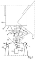
- An object 15 in the outer region 14 can thus be captured or imaged by means of the camera 11.
- the object 15 can be a trailer drawbar of a trailer 16.
- the trailer 16 can be coupled or attached to the motor vehicle 10 with its trailer drawbar via a trailer coupling 17 of the motor vehicle 10. While the motor vehicle 10 is traveling, the trailer 16 or generally the object 15 can execute a relative movement 18 around the trailer coupling 17, which represents a pivoting movement here.
- the trailer 16 is shown in two possible relative positions 19, 19 ', which can move from the relative movement 18.
- the respective current relative position 19, 19 ′ can be described as an articulation angle 20, which can be defined, for example, between a longitudinal axis 21 of the motor vehicle 10 and a longitudinal axis 22 of the object 15.
- the illustrated bend angle 20 is illustrated here for the relative position 19 '.
- the control device 12 can determine in the motor vehicle 10 which maximum articulation angle 23 is possible for the object 15.
- the maximum bending angle 23 is represented here by lines which show a respective edge of the object 15, which causes a collision 24 with the motor vehicle 10 when the maximum bending angle 23 is reached.
- the control device 12 can signal the maximum articulation angle 23 in the motor vehicle 10, as a result of which, for example, a driver assistance system can be configured such that it drives or maneuvers the motor vehicle 10 autonomously or automatically, that is to say without the intervention of a driver, and in this case that for the object 15 specific maximum bending angle 23 is taken into account in order to avoid the collision 24.
- Fig. 2 illustrates a method 25 that can be carried out by the control device 12 for determining the maximum articulation angle 13.
- the control device 12 can use the camera 11 to generate or record a camera image or briefly image 26 of the object 15 against a background 15 'at different measurement times.
- the background 15 ′ can be a driving surface or floor.
- Fig. 3 shows an example of an image 26 of how the object 15 could have been recorded or generated by means of the camera 11.
- This in Fig. 3 The image 26 shown can show the object 15 in the position 19. This image can be viewed as the first image in the sense of the invention.
- scan lines 27 can be defined or defined in the image 26.
- a shape of the scan lines 27 can correspond to the course of the pivoting movement 18, as a point on the object 15 would execute at the respective distance from the motor vehicle 10.
- the scan lines 27 can thus correspond to circle segments, with a corresponding distortion due to the perspective of the camera 11 and / or the optics of the camera 11 changing the shape accordingly.
- a corresponding corresponding scan line is also defined or defined in the other images 26 for each scan line 27.
- a course or a profile 29 which results along the scan line 27 can be determined for each scan line 27 for a predetermined image property 28.
- the image property can be, for example, a color value and / or a brightness value.
- An edge value of an edge detection 30 is preferably used, such as the edge detection 30 along the scan line 27 outputs or can generate, for example on the basis of the brightness values of the pixels of the image 26 along the scan line 27. For example, a difference between the brightness values of neighboring pixels can be calculated as edge detection.
- the profile 29 thus shows a course of the values E of the image property 28 along the scan line 27.
- the profile can be formed in each image 26, so that a correspondingly corresponding profile is also determined for each corresponding scan line of every other image 26. It is crucial here that during a rolling movement of the motor vehicle 10 in the profiles a respective object section or an object segment 31 (see Fig. 1 ) match in all profiles of the corresponding scan lines 27. Only their position along the respective scan line is different, depending on the respective position 19, 19 'of the object 15. In contrast, the background 15' changes due to the rolling movement in each image 26, so that the corresponding background sections or background segments look different in each profile or get lost.
- a respective displacement distance 33 can be added to the profile 29 of the image 26 (see Fig. 1 ) be determined.
- the shift distance indicates how far the corresponding profile of each other image 26 has to be shifted with respect to the profile 29 in order to obtain a maximum match.
- the displacement distance 33 can be carried out, for example, on the basis of a correlation, so that the maximum correlation results in the correlation maximum.
- a step S14 the profile 29 of each scan line 27 of the image 26 can be overlaid with the corresponding profile of each other image 26 shifted by the respective displacement distance 33.
- the overlay can be done, for example, by multiplying the profiles. An overlay profile 34 is thus created for each scan line 27.
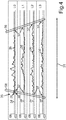
- Fig. 4 shows for four exemplary scan lines L0, L1, L2, L3, their position in Fig. 3 the resulting overlay profile 34 is illustrated.
- a reference pattern 36 can be determined on the basis of a predetermined delimitation criterion 35, which corresponds to the overlay profile, that is to say the object segment 31.
- the delimitation criterion 35 can, for example, provide threshold values 35 ′, the exceeding or falling below of which is signaled by the overlay profile 34 that it is the reference pattern 36 of the object 15.
- the threshold values 35 ' are here for an example in FIG Fig. 4 illustrated.
- control device 12 can then signal either the object boundaries 38 or a maximum articulation angle 23 calculated therefrom.
- the automatic detection of the maximum adjustable articulation angle 23 of a trailer 16 is thus made possible. This increases the dynamic range or the steering angle range for the driver as much as the current object 15 allows.
- a reference pattern 26 thus results overall for each scan line 27.
- This reference pattern 26 contains the information about the trailer geometry and thus the real extent of, for example, a trailer drawbar or generally an object 15. This allows the articulation angle 20 of the trailer 16 to be controlled so far that the Trailer drawbar with a safety distance to the motor vehicle can be regulated or guided.
- the driver can thus regulate significantly larger articulation angles 20 depending on his specific trailer and thus has a higher dynamic range when driving with the trailer 16.
Landscapes
- Engineering & Computer Science (AREA)
- Transportation (AREA)
- Mechanical Engineering (AREA)
- Theoretical Computer Science (AREA)
- General Physics & Mathematics (AREA)
- Physics & Mathematics (AREA)
- Multimedia (AREA)
- Library & Information Science (AREA)
- Combustion & Propulsion (AREA)
- Chemical & Material Sciences (AREA)
- General Engineering & Computer Science (AREA)
- Databases & Information Systems (AREA)
- Data Mining & Analysis (AREA)
- Traffic Control Systems (AREA)
- Image Analysis (AREA)
- Length Measuring Devices By Optical Means (AREA)
Claims (11)
- Procédé (25) de détermination des limites d'objet (38) d'un objet (15) dans une zone externe (14) d'un véhicule automobile (10), dans lequel l'objet (15) est relié en mobilité relative au véhicule automobile (10), et un dispositif de commande (12) du véhicule automobile (10) génère pendant un trajet du véhicule automobile (10) au moyen d'une caméra (11) à au moins deux instants de mesure différents respectivement une image (26) montrant l'objet (15) devant un arrière-plan (15') de la zone externe (14), et- au moins une ligne de balayage (27) est établie sur une première des images (26) et une ligne de balayage correspondante est établie pour chaque ligne de balayage (27) sur chaque autre des images (26), et- pour chaque ligne de balayage (26) de la première image (26) pour une propriété d'image prédéterminée (28), on détermine un profil résultant (29) le long de la ligne de balayage (27) et un profil correspondant résultant le long de la ligne de balayage respectivement correspondante de chaque autre image (26), et- pour chaque profil (29) de chaque ligne de balayage (27) de la première image on détermine une largeur de décalage respective (33) de laquelle le profil correspondant de chaque autre image (26) doit être décalé par rapport au profil (29) afin d'obtenir une correspondance maximale,
caractérisé en ce que- le profil correspondant décalé de la largeur de décalage (33) respective est superposé au profil (29) de chaque ligne de balayage (27) de la première image (26) de sorte que pour chaque ligne de balayage (27) il en résulte un profil superposé (34), le profil superposé (34) étant formé en additionnant ou en multipliant les profils (29), et- dans le profil superposé (34) de chaque ligne de balayage (27), sur la base d'un critère de délimitation (35) prédéterminé, un motif de référence (36) est déterminé, et des limites respectives (37) du motif de référence (36) sont signalisées comme les limites d'objet (38) respectives. - Procédé (25) selon la revendication 1, dans lequel la largeur de décalage (33) est déterminée au moyen d'une corrélation, et dans ce cas, la correspondance maximale est établie à une corrélation maximale.
- Procédé (25) selon l'une quelconque des revendications précédentes, dans lequel le critère de délimitation (35) prévoit une comparaison de valeurs seuil.
- Procédé (25) selon l'une quelconque des revendications précédentes, dans lequel une surface de roulement du véhicule automobile (10) est détectée au moyen de la caméra (11) comme l'arrière-plan (15').
- Procédé (25) selon l'une quelconque des revendications précédentes, dans lequel la propriété d'image prédéterminée (28) comprend une valeur chromatique et/ou une valeur de luminosité et/ou une valeur de contraste et/ou une valeur de détection de contour d'un contenu d'image de l'image (26) respective.
- Procédé (25) selon l'une quelconque des revendications précédentes, dans lequel les lignes de balayage (27) et les lignes de balayage correspondantes présentent un tracé qui correspond à une trajectoire courbe respective le long de laquelle l'objet (15) doit se déplacer lors d'un déplacement relatif (18) en raison de sa position de mobilité relative sur le véhicule automobile (10).
- Procédé (25) selon l'une quelconque des revendications précédentes, dans lequel les limites d'objet (38) permettent de déterminer un angle de pliage maximal (23) spécifique à l'objet selon lequel l'objet (15) entre en collision avec le véhicule automobile (10).
- Procédé selon l'une quelconque des revendications précédentes, dans lequel l'objet (15) est une barre d'attelage d'une remorque (16) tractée par le véhicule automobile (10).
- Procédé selon l'une quelconque des revendications précédentes, dans lequel le motif de référence (34) des lignes de balayage (27) est regroupé en une carte bidimensionnelle de l'objet (15).
- Dispositif de commande (12) pour un véhicule automobile (10), le dispositif de commande (12) présentant un dispositif de calcul aménagé pour exécuter un procédé selon l'une quelconque des revendications précédentes.
- Véhicule automobile (10), comprenant au moins une caméra (11) pour détecter une zone externe (14) du véhicule automobile (10) et comprenant un dispositif de commande (12) selon la revendication 10, le dispositif de commande (12) étant couplé à ladite au moins une caméra (11).
Applications Claiming Priority (1)
| Application Number | Priority Date | Filing Date | Title |
|---|---|---|---|
| DE102017219123.6A DE102017219123B4 (de) | 2017-10-25 | 2017-10-25 | Verfahren zum Ermitteln von Objektgrenzen eines Objekts in einem Außenbereich eines Kraftfahrzeugs sowie Steuervorrichtung und Kraftfahrzeug |
Publications (2)
| Publication Number | Publication Date |
|---|---|
| EP3476696A1 EP3476696A1 (fr) | 2019-05-01 |
| EP3476696B1 true EP3476696B1 (fr) | 2020-07-15 |
Family
ID=63579215
Family Applications (1)
| Application Number | Title | Priority Date | Filing Date |
|---|---|---|---|
| EP18194311.9A Active EP3476696B1 (fr) | 2017-10-25 | 2018-09-13 | Procédé de détermination des limites d'un objet dans une zone externe d'un véhicule automobile ainsi que dispositif de commande et véhicule automobile |
Country Status (3)
| Country | Link |
|---|---|
| US (1) | US10836224B2 (fr) |
| EP (1) | EP3476696B1 (fr) |
| DE (1) | DE102017219123B4 (fr) |
Families Citing this family (4)
| Publication number | Priority date | Publication date | Assignee | Title |
|---|---|---|---|---|
| DE102017219119A1 (de) * | 2017-10-25 | 2019-04-25 | Volkswagen Aktiengesellschaft | Verfahren zur Formerkennung eines Objekts in einem Außenbereich eines Kraftfahrzeugs sowie Kraftfahrzeug |
| DE102019110018B4 (de) * | 2019-04-16 | 2023-09-21 | Valeo Schalter Und Sensoren Gmbh | Verfahren zur Kollisionsvermeidung, System, fahrzeuginternes System, Zugfahrzeug und Signal |
| EP3889906B1 (fr) * | 2020-03-31 | 2024-11-13 | Continental Autonomous Mobility Germany GmbH | Procédé et système de calcul de l'angle d'une remorque de véhicule |
| EP3889903B1 (fr) | 2020-03-31 | 2024-10-23 | Continental Autonomous Mobility Germany GmbH | Procédé et système de calcul de l'angle d'une remorque de véhicule |
Family Cites Families (14)
| Publication number | Priority date | Publication date | Assignee | Title |
|---|---|---|---|---|
| DE102004050149A1 (de) | 2004-10-15 | 2006-04-20 | Daimlerchrysler Ag | Verfahren zur Bestimmung von Deichsel- und Trailerwinkel |
| DE102008045436A1 (de) | 2008-09-02 | 2010-03-04 | Volkswagen Ag | Verfahren und Vorrichtung zum Bestimmen eines Knickwinkels zwischen einem Zugfahrzeug und einem Anhänger |
| US9238483B2 (en) * | 2011-04-19 | 2016-01-19 | Ford Global Technologies, Llc | Trailer backup assist system with trajectory planner for multiple waypoints |
| US9937953B2 (en) * | 2011-04-19 | 2018-04-10 | Ford Global Technologies, Llc | Trailer backup offset determination |
| US9723274B2 (en) * | 2011-04-19 | 2017-08-01 | Ford Global Technologies, Llc | System and method for adjusting an image capture setting |
| DE102011101990B3 (de) | 2011-05-19 | 2012-10-18 | Volkswagen Aktiengesellschaft | Verfahren und Vorrichtung zur Bestimmung eines relativen Deichselwinkels |
| DE102011104256A1 (de) | 2011-06-15 | 2012-07-26 | Audi Ag | Knickwinkelgeber für ein Assistenzsystem eines Kraftfahrzeugs und Verfahren zum Bestimmen eines Knickwinkels |
| US9694850B2 (en) * | 2011-07-18 | 2017-07-04 | Daniel Robert Shepard | Trailer backing up device and table based method |
| DE102011113191B4 (de) | 2011-09-10 | 2022-10-06 | Volkswagen Aktiengesellschaft | Verfahren und Vorrichtung zur Bestimmung eines Knickwinkels zwischen einem Fahrzeug und einem Anhänger |
| DE102014223141B4 (de) * | 2014-11-13 | 2019-06-19 | Volkswagen Aktiengesellschaft | Bestimmung einer Position eines Anhängerkupplungskopfes |
| DE102015201586A1 (de) | 2015-01-29 | 2016-08-04 | Volkswagen Aktiengesellschaft | Verfahren und Vorrichtung zur Wiedererkennung eines Anhängers |
| US10017115B2 (en) * | 2015-11-11 | 2018-07-10 | Ford Global Technologies, Llc | Trailer monitoring system and method |
| US9981690B2 (en) * | 2016-04-13 | 2018-05-29 | Ford Global Technologies, Llc | Target-based trailer backup collision mitigation |
| US10766525B2 (en) * | 2016-07-01 | 2020-09-08 | Ford Global Technologies, Llc | Enhanced yaw rate trailer angle detection initialization |
-
2017
- 2017-10-25 DE DE102017219123.6A patent/DE102017219123B4/de not_active Expired - Fee Related
-
2018
- 2018-09-13 EP EP18194311.9A patent/EP3476696B1/fr active Active
- 2018-10-16 US US16/161,244 patent/US10836224B2/en active Active
Non-Patent Citations (1)
| Title |
|---|
| None * |
Also Published As
| Publication number | Publication date |
|---|---|
| EP3476696A1 (fr) | 2019-05-01 |
| US10836224B2 (en) | 2020-11-17 |
| US20190118594A1 (en) | 2019-04-25 |
| DE102017219123B4 (de) | 2022-12-22 |
| DE102017219123A1 (de) | 2019-04-25 |
Similar Documents
| Publication | Publication Date | Title |
|---|---|---|
| DE102017130566B4 (de) | Sichtsystem zur Erfassung einer Fahrzeugumgebung und Spiegelersatzsystem für ein Fahrzeug mit einem Sichtsystem | |
| EP2987663B1 (fr) | Système d'assistance au conducteur pour un attelage de véhicule utilitaire et procédé d'exécution d'un processus d'attelage | |
| EP3219533B1 (fr) | Système de vision pour un véhicule, notamment pour un véhicule utilitaire | |
| DE10109350B4 (de) | Unterstützungseinrichtung zum Rückwärtseinparken eines Fahrzeugs in Reihe | |
| DE102011104256A1 (de) | Knickwinkelgeber für ein Assistenzsystem eines Kraftfahrzeugs und Verfahren zum Bestimmen eines Knickwinkels | |
| EP3012154B1 (fr) | Procédé et dispositif d'assistance d'un conducteur d'un attelage, notamment d'un attelage de véhicule utilitaire | |
| DE102016011324A1 (de) | Verfahren zur Steuerung eines Zugfahrzeugs bei dessen Heranfahren und Ankuppeln an ein Anhängerfahrzeug | |
| EP3476696B1 (fr) | Procédé de détermination des limites d'un objet dans une zone externe d'un véhicule automobile ainsi que dispositif de commande et véhicule automobile | |
| DE112017005447T5 (de) | Objekterfassungsvorrichtung | |
| DE102011113191B4 (de) | Verfahren und Vorrichtung zur Bestimmung eines Knickwinkels zwischen einem Fahrzeug und einem Anhänger | |
| DE102016115313A1 (de) | Verfahren zum Unterstützen eines Fahrers eines Gespanns, Fahrerassistenzsystem sowie Gespann | |
| EP4308418B1 (fr) | Procédé et système de capture d'environnement pour générer une image environnementale d'un véhicule entier composé d'une pluralité de parties | |
| EP3477249B1 (fr) | Procédé de reconnaissance de forme d'un objet dans une zone extérieure d'un véhicule automobile et véhicule automobile | |
| DE102018005118A1 (de) | Verfahren zum Bestimmen eines Knickwinkels | |
| DE10297590B4 (de) | Fahrunterstützungssystem, Bildausgabevorrichtung und mit Kamera ausgestatteter Stab | |
| DE102017008816A1 (de) | Ausparkassistent | |
| DE102018205694B3 (de) | System und Verfahren zum Erfassen eines Umfelds eines Fahrzeugs, Fahrzeug mit einem System zur Umfelderfassung und Verfahren zum Notbremsen eines Fahrzeugs | |
| WO2020030406A1 (fr) | Système de surveillance par caméra | |
| EP4553770A1 (fr) | Système basé sur une caméra et procédé de détermination de la position d'une remorque | |
| EP3743311B1 (fr) | Procede et dispositif pour opérer un systeme de surveillance vidéo pour un véhicule automobile | |
| WO2024121792A1 (fr) | Système de caméra pour l'attelage précis d'un véhicule remorque à un véhicule tracteur | |
| DE102014110642A1 (de) | Adaptiver elektronischer Rückspiegel für ein Kraftfahrzeug | |
| DE102016117401B4 (de) | Verfahren und Vorrichtung zum Abbilden eines Anhängers mit Begrenzungsmarkierungen | |
| DE102023205719A1 (de) | Verfahren und Vorrichtung zur Anzeige manövrierrelevanter Hilfslinien in einem Display eines Fahrzeugs | |
| DE102016110305B4 (de) | Verfahren zum Unterstützen eines Fahrers eines Kraftfahrzeugs beim Rangieren des Kraftfahrzeugs mit einem Anhänger, Fahrerassistenzsystem sowie Kraftfahrzeug |
Legal Events
| Date | Code | Title | Description |
|---|---|---|---|
| PUAI | Public reference made under article 153(3) epc to a published international application that has entered the european phase |
Free format text: ORIGINAL CODE: 0009012 |
|
| STAA | Information on the status of an ep patent application or granted ep patent |
Free format text: STATUS: THE APPLICATION HAS BEEN PUBLISHED |
|
| AK | Designated contracting states |
Kind code of ref document: A1 Designated state(s): AL AT BE BG CH CY CZ DE DK EE ES FI FR GB GR HR HU IE IS IT LI LT LU LV MC MK MT NL NO PL PT RO RS SE SI SK SM TR |
|
| AX | Request for extension of the european patent |
Extension state: BA ME |
|
| STAA | Information on the status of an ep patent application or granted ep patent |
Free format text: STATUS: REQUEST FOR EXAMINATION WAS MADE |
|
| 17P | Request for examination filed |
Effective date: 20191104 |
|
| RBV | Designated contracting states (corrected) |
Designated state(s): AL AT BE BG CH CY CZ DE DK EE ES FI FR GB GR HR HU IE IS IT LI LT LU LV MC MK MT NL NO PL PT RO RS SE SI SK SM TR |
|
| GRAP | Despatch of communication of intention to grant a patent |
Free format text: ORIGINAL CODE: EPIDOSNIGR1 |
|
| STAA | Information on the status of an ep patent application or granted ep patent |
Free format text: STATUS: GRANT OF PATENT IS INTENDED |
|
| RIC1 | Information provided on ipc code assigned before grant |
Ipc: B62D 13/06 20060101AFI20200319BHEP Ipc: G06K 9/00 20060101ALI20200319BHEP Ipc: B60D 1/62 20060101ALI20200319BHEP Ipc: B60D 1/24 20060101ALI20200319BHEP Ipc: B60D 1/30 20060101ALI20200319BHEP |
|
| INTG | Intention to grant announced |
Effective date: 20200401 |
|
| GRAS | Grant fee paid |
Free format text: ORIGINAL CODE: EPIDOSNIGR3 |
|
| GRAA | (expected) grant |
Free format text: ORIGINAL CODE: 0009210 |
|
| STAA | Information on the status of an ep patent application or granted ep patent |
Free format text: STATUS: THE PATENT HAS BEEN GRANTED |
|
| AK | Designated contracting states |
Kind code of ref document: B1 Designated state(s): AL AT BE BG CH CY CZ DE DK EE ES FI FR GB GR HR HU IE IS IT LI LT LU LV MC MK MT NL NO PL PT RO RS SE SI SK SM TR |
|
| REG | Reference to a national code |
Ref country code: CH Ref legal event code: EP Ref country code: GB Ref legal event code: FG4D Free format text: NOT ENGLISH |
|
| REG | Reference to a national code |
Ref country code: DE Ref legal event code: R096 Ref document number: 502018001898 Country of ref document: DE |
|
| REG | Reference to a national code |
Ref country code: IE Ref legal event code: FG4D Free format text: LANGUAGE OF EP DOCUMENT: GERMAN |
|
| REG | Reference to a national code |
Ref country code: AT Ref legal event code: REF Ref document number: 1290734 Country of ref document: AT Kind code of ref document: T Effective date: 20200815 |
|
| REG | Reference to a national code |
Ref country code: LT Ref legal event code: MG4D |
|
| REG | Reference to a national code |
Ref country code: NL Ref legal event code: MP Effective date: 20200715 |
|
| PG25 | Lapsed in a contracting state [announced via postgrant information from national office to epo] |
Ref country code: FI Free format text: LAPSE BECAUSE OF FAILURE TO SUBMIT A TRANSLATION OF THE DESCRIPTION OR TO PAY THE FEE WITHIN THE PRESCRIBED TIME-LIMIT Effective date: 20200715 Ref country code: NO Free format text: LAPSE BECAUSE OF FAILURE TO SUBMIT A TRANSLATION OF THE DESCRIPTION OR TO PAY THE FEE WITHIN THE PRESCRIBED TIME-LIMIT Effective date: 20201015 Ref country code: BG Free format text: LAPSE BECAUSE OF FAILURE TO SUBMIT A TRANSLATION OF THE DESCRIPTION OR TO PAY THE FEE WITHIN THE PRESCRIBED TIME-LIMIT Effective date: 20201015 Ref country code: SE Free format text: LAPSE BECAUSE OF FAILURE TO SUBMIT A TRANSLATION OF THE DESCRIPTION OR TO PAY THE FEE WITHIN THE PRESCRIBED TIME-LIMIT Effective date: 20200715 Ref country code: GR Free format text: LAPSE BECAUSE OF FAILURE TO SUBMIT A TRANSLATION OF THE DESCRIPTION OR TO PAY THE FEE WITHIN THE PRESCRIBED TIME-LIMIT Effective date: 20201016 Ref country code: PT Free format text: LAPSE BECAUSE OF FAILURE TO SUBMIT A TRANSLATION OF THE DESCRIPTION OR TO PAY THE FEE WITHIN THE PRESCRIBED TIME-LIMIT Effective date: 20201116 Ref country code: ES Free format text: LAPSE BECAUSE OF FAILURE TO SUBMIT A TRANSLATION OF THE DESCRIPTION OR TO PAY THE FEE WITHIN THE PRESCRIBED TIME-LIMIT Effective date: 20200715 Ref country code: LT Free format text: LAPSE BECAUSE OF FAILURE TO SUBMIT A TRANSLATION OF THE DESCRIPTION OR TO PAY THE FEE WITHIN THE PRESCRIBED TIME-LIMIT Effective date: 20200715 Ref country code: HR Free format text: LAPSE BECAUSE OF FAILURE TO SUBMIT A TRANSLATION OF THE DESCRIPTION OR TO PAY THE FEE WITHIN THE PRESCRIBED TIME-LIMIT Effective date: 20200715 |
|
| PG25 | Lapsed in a contracting state [announced via postgrant information from national office to epo] |
Ref country code: PL Free format text: LAPSE BECAUSE OF FAILURE TO SUBMIT A TRANSLATION OF THE DESCRIPTION OR TO PAY THE FEE WITHIN THE PRESCRIBED TIME-LIMIT Effective date: 20200715 Ref country code: LV Free format text: LAPSE BECAUSE OF FAILURE TO SUBMIT A TRANSLATION OF THE DESCRIPTION OR TO PAY THE FEE WITHIN THE PRESCRIBED TIME-LIMIT Effective date: 20200715 Ref country code: RS Free format text: LAPSE BECAUSE OF FAILURE TO SUBMIT A TRANSLATION OF THE DESCRIPTION OR TO PAY THE FEE WITHIN THE PRESCRIBED TIME-LIMIT Effective date: 20200715 Ref country code: IS Free format text: LAPSE BECAUSE OF FAILURE TO SUBMIT A TRANSLATION OF THE DESCRIPTION OR TO PAY THE FEE WITHIN THE PRESCRIBED TIME-LIMIT Effective date: 20201115 |
|
| PG25 | Lapsed in a contracting state [announced via postgrant information from national office to epo] |
Ref country code: NL Free format text: LAPSE BECAUSE OF FAILURE TO SUBMIT A TRANSLATION OF THE DESCRIPTION OR TO PAY THE FEE WITHIN THE PRESCRIBED TIME-LIMIT Effective date: 20200715 |
|
| REG | Reference to a national code |
Ref country code: DE Ref legal event code: R097 Ref document number: 502018001898 Country of ref document: DE |
|
| PG25 | Lapsed in a contracting state [announced via postgrant information from national office to epo] |
Ref country code: SM Free format text: LAPSE BECAUSE OF FAILURE TO SUBMIT A TRANSLATION OF THE DESCRIPTION OR TO PAY THE FEE WITHIN THE PRESCRIBED TIME-LIMIT Effective date: 20200715 Ref country code: IT Free format text: LAPSE BECAUSE OF FAILURE TO SUBMIT A TRANSLATION OF THE DESCRIPTION OR TO PAY THE FEE WITHIN THE PRESCRIBED TIME-LIMIT Effective date: 20200715 Ref country code: EE Free format text: LAPSE BECAUSE OF FAILURE TO SUBMIT A TRANSLATION OF THE DESCRIPTION OR TO PAY THE FEE WITHIN THE PRESCRIBED TIME-LIMIT Effective date: 20200715 Ref country code: CZ Free format text: LAPSE BECAUSE OF FAILURE TO SUBMIT A TRANSLATION OF THE DESCRIPTION OR TO PAY THE FEE WITHIN THE PRESCRIBED TIME-LIMIT Effective date: 20200715 Ref country code: DK Free format text: LAPSE BECAUSE OF FAILURE TO SUBMIT A TRANSLATION OF THE DESCRIPTION OR TO PAY THE FEE WITHIN THE PRESCRIBED TIME-LIMIT Effective date: 20200715 Ref country code: RO Free format text: LAPSE BECAUSE OF FAILURE TO SUBMIT A TRANSLATION OF THE DESCRIPTION OR TO PAY THE FEE WITHIN THE PRESCRIBED TIME-LIMIT Effective date: 20200715 |
|
| PLBE | No opposition filed within time limit |
Free format text: ORIGINAL CODE: 0009261 |
|
| STAA | Information on the status of an ep patent application or granted ep patent |
Free format text: STATUS: NO OPPOSITION FILED WITHIN TIME LIMIT |
|
| PG25 | Lapsed in a contracting state [announced via postgrant information from national office to epo] |
Ref country code: AL Free format text: LAPSE BECAUSE OF FAILURE TO SUBMIT A TRANSLATION OF THE DESCRIPTION OR TO PAY THE FEE WITHIN THE PRESCRIBED TIME-LIMIT Effective date: 20200715 |
|
| REG | Reference to a national code |
Ref country code: BE Ref legal event code: MM Effective date: 20200930 |
|
| 26N | No opposition filed |
Effective date: 20210416 |
|
| PG25 | Lapsed in a contracting state [announced via postgrant information from national office to epo] |
Ref country code: SK Free format text: LAPSE BECAUSE OF FAILURE TO SUBMIT A TRANSLATION OF THE DESCRIPTION OR TO PAY THE FEE WITHIN THE PRESCRIBED TIME-LIMIT Effective date: 20200715 Ref country code: LU Free format text: LAPSE BECAUSE OF NON-PAYMENT OF DUE FEES Effective date: 20200913 |
|
| PG25 | Lapsed in a contracting state [announced via postgrant information from national office to epo] |
Ref country code: BE Free format text: LAPSE BECAUSE OF NON-PAYMENT OF DUE FEES Effective date: 20200930 Ref country code: SI Free format text: LAPSE BECAUSE OF FAILURE TO SUBMIT A TRANSLATION OF THE DESCRIPTION OR TO PAY THE FEE WITHIN THE PRESCRIBED TIME-LIMIT Effective date: 20200715 Ref country code: IE Free format text: LAPSE BECAUSE OF NON-PAYMENT OF DUE FEES Effective date: 20200913 |
|
| REG | Reference to a national code |
Ref country code: CH Ref legal event code: PL |
|
| PG25 | Lapsed in a contracting state [announced via postgrant information from national office to epo] |
Ref country code: TR Free format text: LAPSE BECAUSE OF FAILURE TO SUBMIT A TRANSLATION OF THE DESCRIPTION OR TO PAY THE FEE WITHIN THE PRESCRIBED TIME-LIMIT Effective date: 20200715 Ref country code: MT Free format text: LAPSE BECAUSE OF FAILURE TO SUBMIT A TRANSLATION OF THE DESCRIPTION OR TO PAY THE FEE WITHIN THE PRESCRIBED TIME-LIMIT Effective date: 20200715 Ref country code: CY Free format text: LAPSE BECAUSE OF FAILURE TO SUBMIT A TRANSLATION OF THE DESCRIPTION OR TO PAY THE FEE WITHIN THE PRESCRIBED TIME-LIMIT Effective date: 20200715 |
|
| PG25 | Lapsed in a contracting state [announced via postgrant information from national office to epo] |
Ref country code: MK Free format text: LAPSE BECAUSE OF FAILURE TO SUBMIT A TRANSLATION OF THE DESCRIPTION OR TO PAY THE FEE WITHIN THE PRESCRIBED TIME-LIMIT Effective date: 20200715 Ref country code: MC Free format text: LAPSE BECAUSE OF FAILURE TO SUBMIT A TRANSLATION OF THE DESCRIPTION OR TO PAY THE FEE WITHIN THE PRESCRIBED TIME-LIMIT Effective date: 20200715 |
|
| PG25 | Lapsed in a contracting state [announced via postgrant information from national office to epo] |
Ref country code: LI Free format text: LAPSE BECAUSE OF NON-PAYMENT OF DUE FEES Effective date: 20210930 Ref country code: CH Free format text: LAPSE BECAUSE OF NON-PAYMENT OF DUE FEES Effective date: 20210930 |
|
| P01 | Opt-out of the competence of the unified patent court (upc) registered |
Effective date: 20230523 |
|
| PGFP | Annual fee paid to national office [announced via postgrant information from national office to epo] |
Ref country code: DE Payment date: 20240930 Year of fee payment: 7 |
|
| PGFP | Annual fee paid to national office [announced via postgrant information from national office to epo] |
Ref country code: GB Payment date: 20240924 Year of fee payment: 7 |
|
| PGFP | Annual fee paid to national office [announced via postgrant information from national office to epo] |
Ref country code: FR Payment date: 20240925 Year of fee payment: 7 |
|
| REG | Reference to a national code |
Ref country code: AT Ref legal event code: MM01 Ref document number: 1290734 Country of ref document: AT Kind code of ref document: T Effective date: 20230913 |
|
| PG25 | Lapsed in a contracting state [announced via postgrant information from national office to epo] |
Ref country code: AT Free format text: LAPSE BECAUSE OF NON-PAYMENT OF DUE FEES Effective date: 20230913 |
|
| PG25 | Lapsed in a contracting state [announced via postgrant information from national office to epo] |
Ref country code: AT Free format text: LAPSE BECAUSE OF NON-PAYMENT OF DUE FEES Effective date: 20230913 |
|
| PGFP | Annual fee paid to national office [announced via postgrant information from national office to epo] |
Ref country code: AT Payment date: 20260410 Year of fee payment: 5 |