EP2987739B1 - Récipients de distribution et de tri - Google Patents
Récipients de distribution et de tri Download PDFInfo
- Publication number
- EP2987739B1 EP2987739B1 EP14181303.0A EP14181303A EP2987739B1 EP 2987739 B1 EP2987739 B1 EP 2987739B1 EP 14181303 A EP14181303 A EP 14181303A EP 2987739 B1 EP2987739 B1 EP 2987739B1
- Authority
- EP
- European Patent Office
- Prior art keywords
- container
- side walls
- boundary
- bar
- sorting
- Prior art date
- Legal status (The legal status is an assumption and is not a legal conclusion. Google has not performed a legal analysis and makes no representation as to the accuracy of the status listed.)
- Not-in-force
Links
- 238000000034 method Methods 0.000 claims description 8
- 238000000926 separation method Methods 0.000 description 6
- 230000005484 gravity Effects 0.000 description 4
- 239000002689 soil Substances 0.000 description 4
- 238000004519 manufacturing process Methods 0.000 description 3
- 238000011161 development Methods 0.000 description 2
- 230000018109 developmental process Effects 0.000 description 2
- 239000000463 material Substances 0.000 description 2
- 230000000087 stabilizing effect Effects 0.000 description 2
- 230000001419 dependent effect Effects 0.000 description 1
- 238000006073 displacement reaction Methods 0.000 description 1
- 230000000694 effects Effects 0.000 description 1
- 230000005489 elastic deformation Effects 0.000 description 1
- 230000008921 facial expression Effects 0.000 description 1
- 238000001746 injection moulding Methods 0.000 description 1
- 230000013011 mating Effects 0.000 description 1
- 239000002184 metal Substances 0.000 description 1
- 230000003278 mimic effect Effects 0.000 description 1
- 230000000284 resting effect Effects 0.000 description 1
- 239000007787 solid Substances 0.000 description 1
- 239000000243 solution Substances 0.000 description 1
- 230000006641 stabilisation Effects 0.000 description 1
- 238000011105 stabilization Methods 0.000 description 1
Images




Classifications
-
- B—PERFORMING OPERATIONS; TRANSPORTING
- B65—CONVEYING; PACKING; STORING; HANDLING THIN OR FILAMENTARY MATERIAL
- B65D—CONTAINERS FOR STORAGE OR TRANSPORT OF ARTICLES OR MATERIALS, e.g. BAGS, BARRELS, BOTTLES, BOXES, CANS, CARTONS, CRATES, DRUMS, JARS, TANKS, HOPPERS, FORWARDING CONTAINERS; ACCESSORIES, CLOSURES, OR FITTINGS THEREFOR; PACKAGING ELEMENTS; PACKAGES
- B65D11/00—Containers having bodies formed by interconnecting or uniting two or more rigid, or substantially rigid, components made wholly or mainly of plastics material
- B65D11/18—Containers having bodies formed by interconnecting or uniting two or more rigid, or substantially rigid, components made wholly or mainly of plastics material collapsible, i.e. with walls hinged together or detachably connected
- B65D11/1866—Containers having bodies formed by interconnecting or uniting two or more rigid, or substantially rigid, components made wholly or mainly of plastics material collapsible, i.e. with walls hinged together or detachably connected with detachable components
- B65D11/1873—Containers having bodies formed by interconnecting or uniting two or more rigid, or substantially rigid, components made wholly or mainly of plastics material collapsible, i.e. with walls hinged together or detachably connected with detachable components all walls are detached from each other to collapse the container
-
- B—PERFORMING OPERATIONS; TRANSPORTING
- B07—SEPARATING SOLIDS FROM SOLIDS; SORTING
- B07C—POSTAL SORTING; SORTING INDIVIDUAL ARTICLES, OR BULK MATERIAL FIT TO BE SORTED PIECE-MEAL, e.g. BY PICKING
- B07C3/00—Sorting according to destination
- B07C3/008—Means for collecting objects, e.g. containers for sorted mail items
-
- B—PERFORMING OPERATIONS; TRANSPORTING
- B65—CONVEYING; PACKING; STORING; HANDLING THIN OR FILAMENTARY MATERIAL
- B65D—CONTAINERS FOR STORAGE OR TRANSPORT OF ARTICLES OR MATERIALS, e.g. BAGS, BARRELS, BOTTLES, BOXES, CANS, CARTONS, CRATES, DRUMS, JARS, TANKS, HOPPERS, FORWARDING CONTAINERS; ACCESSORIES, CLOSURES, OR FITTINGS THEREFOR; PACKAGING ELEMENTS; PACKAGES
- B65D21/00—Nestable, stackable or joinable containers; Containers of variable capacity
- B65D21/02—Containers specially shaped, or provided with fittings or attachments, to facilitate nesting, stacking, or joining together
- B65D21/0209—Containers specially shaped, or provided with fittings or attachments, to facilitate nesting, stacking, or joining together stackable or joined together one-upon-the-other in the upright or upside-down position
- B65D21/0212—Containers presenting local stacking elements protruding from the upper or lower edge of a side wall, e.g. handles, lugs, ribs, grooves
-
- B—PERFORMING OPERATIONS; TRANSPORTING
- B65—CONVEYING; PACKING; STORING; HANDLING THIN OR FILAMENTARY MATERIAL
- B65D—CONTAINERS FOR STORAGE OR TRANSPORT OF ARTICLES OR MATERIALS, e.g. BAGS, BARRELS, BOTTLES, BOXES, CANS, CARTONS, CRATES, DRUMS, JARS, TANKS, HOPPERS, FORWARDING CONTAINERS; ACCESSORIES, CLOSURES, OR FITTINGS THEREFOR; PACKAGING ELEMENTS; PACKAGES
- B65D25/00—Details of other kinds or types of rigid or semi-rigid containers
- B65D25/005—Side walls formed with an aperture or a movable portion arranged to allow removal or insertion of contents
Definitions
- the present invention relates to a container for the transport and storage of articles having a substantially rectangular bottom and two opposite side walls according to the preamble of claim 1.
- the present invention relates to a sorting and / or delivery container for transport and storage of mail.
- the invention relates to a sorting shelf, a sorting and delivery system consisting of the container and the sorting shelf and a method for filling a container.
- sorting workstations When delivering mail items, these are first sorted into so-called sorting workstations in compartments sorted by delivery areas before they are subsequently relocated from these sorting bins into delivery bins, which serve the postman in the delivery or delivery.
- a major disadvantage is to be seen in particular in the fact that the mail items from the sorting compartments in the post office branch must be reloaded into the delivery containers, which increases the time and resources required.
- WO 2011/131301 A1 is a container known, which could be suitable in principle for the application described above, since there one of the four side walls can be removed so as to sort the mail laterally and then to close for delivery again with the removed side wall.
- the removed and loose side wall can be stored in a specially designed receptacle in the bottom area.
- the removal of a side wall is at the expense of the stability of the container as a whole, since this is no longer so stiff due to the lack of connection of the side walls on one side and the three remaining side walls can easily twist.
- this system is also disadvantageous for the purpose described above in that the side wall not connected to the container is otherwise stored as intended and subsequently can no longer be assigned to the correct container or even lost. In addition, it requires several handling steps for removing and attaching the side wall.
- a container in which, according to one embodiment, a multi-membered sidewall can be pivotally transferred from a first, built-up position to a second position in which the members are disposed adjacent the bottom portion of the container.
- a pivotable solution has the disadvantage that pivoting space is needed to release the side wall for filling the container.
- the document also discloses an embodiment with a slidably mounted via a slotted guide bar, but which is in its second position on the bottom part and thus does not release the page completely for loading.
- the object of the present invention is to provide a container for the transport and storage of objects, which is flexible and eliminates the disadvantages described above.
- a further object is to provide a sorting rack, a sorting and delivery system consisting of the container and the sorting rack and a method for filling a container, which offers time savings in the sorting and subsequent delivery of items.
- the container or sorting and delivery container according to the invention is suitable for the transport and / or storage of objects, in particular of mailpieces, such as letters, postcards and Infopost.
- This has a substantially rectangular bottom and two opposing side walls or side boundaries.
- a movable side boundary is provided with the two is coupled to adjacent side walls or side boundaries.
- This may in particular be a strip extending between the two side walls or side boundaries, preferably a thin and narrow strip.
- This side boundary or bar can be transferred from a first position in which limits the container to the side, in a second position in which the side boundary or strip is substantially at the level of the soil and thus the container to the side , in particular complete, releases or provides free access to the container interior from this side.
- the side boundary is slidably mounted on the adjacent side walls by means of a slotted guide.
- a slotted guide defines a certain movement of the side boundary and thus facilitates the daily handling during use of the container.
- the displaceable side boundary for example, at the facing to the adjacent side walls or corner posts side edges at least one, in particular integrally formed projection, in particular guide pin, which engages in a corresponding formed on the adjacent side walls or corner posts backdrop.
- the side boundary or at least a substantial portion thereof, is below the level of a cargo bed of the container so that the side fence frees the cargo bed of the container to the side or lateral access to the cargo bed is not obstructed by the side restriction ,
- the container is configured so that the side fence in the second position is laterally adjacent and optionally adjacent the bottom edge of the side.
- the side boundary is oriented substantially vertically or oriented parallel to the orientation in the first position.
- the side boundary or strip in particular of the section extending between the two side walls, may be spaced apart from the ground in the first position in order to be able to better support laterally higher objects.
- the first limited to all sides container is opened on one side, so that it is easier to fill or load from the side.
- the lateral filling of the container according to the invention is particularly advantageous when a plurality of identical containers are stacked on top of each other and thus the container can not be loaded or filled from above.
- the movable side boundary here is not only a side wall part, but preferably the sole or the entire side boundary on this side of the container (with the exception of the below described and optional stabilizing strut, which may be provided for stabilizing the upper ends of the adjacent side walls). In other words, when the side boundary is in the second position, the complete side of the container is open.
- a significant advantage of the container according to the invention is the fact that the side wall in both the first position and in the second position a Forms link between the adjacent side walls or side boundaries and stabilizes them.
- the side boundary remains connected when transferring from one to the other position on the container and thus does not need to be stored somewhere else or even lost.
- a higher stability of the container is ensured.
- the letters can be sorted directly into those containers which are subsequently used for delivery.
- the process of switching the articles or mail items from one container to another is saved.
- a shelving system can be created, which can be easily increased or reduced or converted, resulting in a customizable shelving system from the containers according to the invention, without having to provide specially made furniture or shelves.
- the container according to the invention is suitable as a sorting and delivery container, in particular in the field of the postal service.
- a sorting and delivery container in particular in the field of the postal service.
- other applications are conceivable in which, for example, a large side opening for filling the container via conveyor systems or robots is needed.
- the vertical dimensions of the lateral boundary may correspond substantially to the height of the floor. Thereby closes the side boundary at the top with a loading surface of the soil and below with a footprint of the soil flush.
- the upper edge of the side boundary when in the second position, may protrude slightly above the cargo bed and form an edge. This ensures that the items or mail items placed on the loading area, such as letters, do not accidentally slip out of the container but are stopped at the edge formed by the lowered side boundary.
- This projection of the lateral boundary over the floor loading surface can be realized by a slightly larger vertical dimension of the lateral boundary or by a corresponding design of the sliding or other facial expressions responsible for transferring the lateral boundary from the first to the second position.
- the movable side boundary in the first and / or second position can be locked without tools and releasably lockable.
- corresponding latching geometries can be provided which hold the side boundary in the first and / or second position and can be released in accordance with the displacement force or pivoting force.
- the gate can be designed so that the side boundary is trapped at least in the first position and does not solve by itself, for example by gravity, from this first position.
- the scenery can also be designed so that it has a kind of trap in the respective position, which can only be overcome by a brief lifting, that is contrary to gravity.
- the two side walls can be detachably connected to the floor, in particular via a plug connection. This not only facilitates the production of the container by the separate production of side walls and floor, but can also store the individual parts for storing space saving in the assembled state or deliver.
- the free ends or the spaced-apart from the bottom ends of the side walls can be connected to each other via struts or bands.
- these struts or bands are detachably connectable to the side walls.
- stabilization struts preferably plastic profiles can be used, which can be positively inserted into the side walls.
- the two opposing side walls can have large access openings for lateral viewing or intervention in the container interior.
- the two opposite side walls may be U-shaped, so that the side walls in the region of the bottom form a transverse wall as a side boundary for the objects mounted on the bottom surface.
- higher side wall sections or corner pillars may be provided, which on the one hand serve to support the side boundary on the other two opposite sides and on the other to stack containers one above the other.
- two identical containers can be stacked one above the other, even if the side boundary is in the first and / or second position. This allows the stacking of several containers one above the other to a shelving system or just for space-saving storage in the air.
- the loading surface of the soil may have a structure or texture, in particular a multiplicity of grooves or ribs extending parallel to the side walls, which prevents objects, in particular letters, from sliding back and forth on the loading surface.
- the invention also provides a method for filling a container according to one or more of the aforementioned aspects.
- This method comprises the following steps: transferring from one, via a slotted guide (44, 46) slidably mounted, coupled to the two adjacent side walls Sidewall boundary from a first position spaced from the floor in which it bounds the container to the side, in a second position substantially at the level of the bottom, in which it releases the container to the side; lateral filling of the container with the objects; and returning the sidewall boundary from the second position to the first position.
- Fig. 1 shows a container 2 according to the invention, which can be used as a sorting and delivery container for transporting and storing mailpieces and other objects.
- the container 2 has a substantially rectangular bottom 4, on whose short sides substantially vertically upwardly extending side walls 6 and 8 are provided. On the long sides no side walls, but only side boundaries in the form of movable, thin-walled and narrow strips 10 and 12 are provided.
- the illustrated container is a hybrid container in which two different embodiments of strips 10 and 12 are shown on two opposite sides.
- the strip 10 is a side boundary according to a first embodiment which is pivotable with respect to the side walls 6 and 8.
- the bar 12 is a side boundary according to a second embodiment, which is displaceable with respect to the side walls 6 and 8.
- both the side boundary according to the first embodiment (strip 10) and the side boundary according to the second embodiment (strip 12) are in a first position. In the first position, the strips 10 and 12 are spaced from the bottom 4 and thus ensure that objects placed in the container 2 do not fall laterally from the container 2.
- the side walls 6 and 8 on the short side of the container 2 have a substantially U-shape with a large recess 14, which allow a view and also an engagement in the container interior.
- the recess 14 is bounded by two vertical side wall portions or side wall flanks 16 and a transverse wall 18 connected to the bottom 4.
- a handle opening 20 for lifting the container 2 is centrally provided in each case.
- transverse struts are provided, which connect the respective flank 16 of the two opposite side walls 6 and 8 with each other and thus stabilize the side walls 6 and 8.
- the two transverse struts 22 are positively and releasably fastened to the flanks 16.
- the two side walls 6 and 8 are also connected by means of a plug connection releasably connected to the side edges of the bottom 4.
- the bottom 4, the side walls 6 and 8, the side boundaries or strips 10 and 12, the cross braces 22 may all be made of plastic, optionally with different material properties corresponding to the respective loads.
- the floor 4 has a loading surface 24 which is flat and may have a surface structure or texture 26 which generates a higher surface friction value so that the articles deposited on the loading surface 24, in particular letters, do not slide back and forth.
- This surface structure 26 may in particular be grooves or ribs which run parallel to the side walls 6 and 8.
- the loading area can have a small projecting retaining edge 28 which serves to support objects resting on the loading area 24, not so easily slip off the loading surface 24 when the container 2 is moved and the Side limits 10 or 12 are not yet in the raised first position.
- the Fig. 2 shows the container 2, in which the bar 10 has been brought from the first position in which it has a lateral limiting function, in the second position in which it allows or does not obstruct free access from the side.
- the strip 10 is a pivotable strip which has at both end sides of the strip 10 formed thereon pivot arms 30 which are provided with pivot pins 32 which are pivotally mounted in corresponding formed on the inside of the side walls 6 and 8 shots 34.
- the bar 10 is between in the Fig. 1 shown first position and in the Fig. 2 shown second position by 180 ° outwardly pivoted. Like from the Fig. 2 can be seen well, is the bar 10 in the second position laterally and parallel to the longitudinal outer edge of the bottom 4.
- the vertical height or width of the bar 10 corresponds to the height of the bottom 4.
- the swivel mimic and the bar 10 may be designed so that the upwardly facing edge of the bar, when the bar in the second position ( Fig. 2 ), something over the loading surface 24 protrudes, forms an edge and thereby also assumes a certain load securing function.
- locking pins 36 are further provided on the outer edges of the strip 10, which engage in the first position in corresponding formed on the side wall locking receptacles 38 form-fitting manner.
- the bar 10 In order to introduce the locking pin 36 in the locking receptacle 38, the bar 10 must be raised slightly upwards.
- the receptacles 34 are therefore designed as vertical slots, which allow this vertical degree of freedom for locking the locking pin 36 in the locking receptacles 38.
- the bar 10 To release the lock, the bar 10 must be raised slightly vertically against the force of gravity before the locking receptacle 38 release the pivotal movement of the bar 10 to the outside.
- the locking can alternatively be accomplished by locking geometries or locking lugs.
- the strip 10 also has a hand-wide recess 40 centrally at the upper edge in the first position and lower edge in the second position, which allows the user to reach under the strip 10 when in the second folded-down position is, the easier it is to flip the bar 10 back to the first position.
- the Fig. 4 shows the same hybrid container 2, but the rear side with a side boundary according to the second embodiment in the form of a vertically displaceable bar 12.
- the bar 12 is formed similar to the bar 10, but at both ends thereof has guide arms 42 each having one or more outwardly or to the side walls 6 and 8 facing guide pins 44, which are guided in guide slots 46 which are formed on the side walls 6 and 8 or more precisely on the flanks 16.
- the sliding bar 12 can be between in the Fig. 4 shown first position in the in the Fig. 5 shown vertically displace or lower, so that the loading area 24 is released in the second position.
- the dimensions of the strip 12 between the two guide arms 42 substantially correspond to those of the strip 10 with the exception of the handle recess 48, which is located both in the first and in the second position at the lower edge of the bar 12.
- the sliding bar 12 is or the guide slot 46 are configured so that the bar 12 does not automatically, for example due to gravity, from the first position dissolves and slips into the second position.
- the upper that is spaced from the bottom portion of the guide slot 46, an undercut 50, the guide pin 44, when the bar 12 is in the first position, engages behind.
- the guide pin 44 can be brought by material-related elastic deformation of the bar 12 in and out of the undercut 50.
- neither the swiveling side boundary or bar 10 nor the displaceable side boundary or bar 12 limits the filling volume of the container 2, since these do not pivot when moving or moving from the first to the second position Run through or cut substantially cuboid interior of the container 2.
- the container 2, in particular the bottom 4, the two side walls 6 and 8 and the bar 10 and 12 and the transverse struts 22 can be mounted apart and together and thus can be manufactured individually. More precisely, the two side walls 6 and 8 on the short side edges of the bottom 4 via corresponding connectors 52 and 54 releasably connect to each other.
- the cross braces 22 and the strips 10 and 12 between the side walls 6 and 8 are used. Are the side walls 6 and 8 respectively connected to the ground, the cross struts 22 and the strips 10 and 12 between the side walls 6 and 8 positively caught or absorbed.
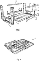
- the individual parts of the container 2 can also be folded and stored to save space, as in the Fig. 8 is shown.
- the side wall portions 6 and 8 have at their lower outer sides and their upper inner sides stack edges 56 and 58, so that two identical containers 2 can be stacked one above the other.
- the container 2 according to the invention can be built by the container a kind of customizable shelving system (if the sorting shelf described below is not available), each container 2 are filled from the longitudinal side. If each container 2 is assigned to a specific delivery area, the mailpieces can be sorted directly to the container provided for delivery in this delivery area.
- a sorting shelf 60 is shown.
- the sorting rack 60 which is only shown systematically, has at least one control compartment 62, which has a shelf 64, two side walls 66 perpendicular thereto and a control compartment ceiling 68. Between the two rule side walls 66 is located about halfway up the control compartment 62 in the rear region of the side walls 66, a cross bar 70, on which a plurality of vertically arranged separation register 72 to each other in the transverse direction slidably and pivotally mounted about the cross bar 70.
- the thin, made of metal or plastic separating register 72 have at their on the transverse to the cross bar 70 opposite side obliquely upwardly set end edges, so that when inserting the container 2 in the control compartment 62, as this state in the Fig. 11 is shown, the separation register 72, which initially rest on the control shelf 62, can slide through the bottom 4 up on the bed 24.
- the separation registers 72 are located on the loading surface 24 between the two side walls 6 and 8.
- first of all the rear side boundary or bar 10 or 12 must first be brought into the second position become. For sorting the mailpieces between the separation registers 72 and the front side boundary or the bar 10 and 12 can be lowered so as to allow better access to the container.
- the container 2 can be removed from the control compartment 62, thereby also the separation register 72 between the mail items, which are no longer needed after sorting and connected to the sorting shelf 60, pulled out of the container 2. Subsequently, the two side boundaries 10 and 12 can be returned to the first position to prevent the mailings from falling out of the container 2 laterally.
- the retaining edge 28 or the slightly projecting strips 10 and 12 prevent the withdrawal of the container 2 from the rule compartment 62 that the mail remains in the container 2, as long as the side boundaries 10 and 12 are not yet folded up.
- the container 2 according to the invention and the sorting shelf 60 have been described with reference to preferred embodiments, but are not limited to these.
- the first embodiment of the container can be changed to the effect that the pivotable side strips 10 are not articulated via pivot arms 30 on the side walls 6 and 8, but hinged to the longitudinal edge of the bottom 4 are hinged.
- the container 2 shown in the figures has different types or embodiments of the side boundaries.
- the side boundaries will be either pivotable on both sides or slidable on both sides. It is also conceivable that a solid side wall is also provided on a longitudinal side instead of the movable sidewall boundary.
- the side walls 6 and 8 can also be made conical, so that the guide of the sliding side wall boundary is then not made vertically, but adjusted accordingly to the outside.
- a container can be completely opened at least on one side by a movable sidewall boundary between a first position in which it acts as a side wall part, in a second position in which it releases the one side of the container transferred can and vice versa.
- the side wall boundary forms a link between the adjacent side walls, so that a sufficient stability of the container is ensured regardless of the respective position of the side wall and the side wall boundary always remains connected to the container.
Landscapes
- Engineering & Computer Science (AREA)
- Mechanical Engineering (AREA)
- Rigid Containers With Two Or More Constituent Elements (AREA)
Claims (10)
- Contenant (2), en particulier contenant de tri et de distribution, pour le transport et le stockage d'objets, en particulier d'envois postaux, avec un fond (4) sensiblement rectangulaire et deux parois latérales (6, 8) se faisant face l'une l'autre, dans lequel
est prévue, au moins au niveau d'un des côtés restants du contenant, une délimitation latérale, qui est couplée aux deux parois latérales (6, 8) adjacentes et qui peut être transférée depuis une première position, dans laquelle elle délimite le contenant (2) sur le côté, dans une deuxième position se trouvant sensiblement sur ou en dessous du niveau d'une surface de chargement (24) du contenant (2), dans laquelle position elle est disposée latéralement à côté d'un bord latéral du fond (4) en étant orientée sensiblement de manière verticale et dégage en direction du côté la surface de chargement (24) du contenant (2),
caractérisé en ce
que la délimitation latérale (12) est montée de manière à pouvoir être coulissée au niveau des parois latérales (6, 8) adjacentes à celle-ci et est guidée par l'intermédiaire d'un guidage à coulisse (44, 46) entre la première et la deuxième position. - Contenant (2) selon la revendication 1, caractérisé en ce que des dimensions verticales de la délimitation latérale (10 ; 12) s'étendant dans la première position entre les deux parois latérales (6, 8) adjacentes correspondent sensiblement à la hauteur du bord latéral du fond (4).
- Contenant (2) selon la revendication 1, caractérisé en ce qu'un bord supérieur de la délimitation latérale (10 ; 12) dépasse, dans la deuxième position, vers le haut légèrement au-dessus d'une surface de chargement (24) du fond (4).
- Contenant (2) selon l'une quelconque des revendications précédentes, caractérisé en ce que la délimitation latérale (10 ; 12) peut être bloquée sans outil et de manière amovible dans la première et/ou deuxième position, en particulier par l'intermédiaire de géométriques d'enclenchement ou d'une contre-dépouille.
- Contenant (2) selon l'une quelconque des revendications précédentes, caractérisé en ce que les deux parois latérales (6, 8) sont reliées de manière amovible au fond (4), en particulier par l'intermédiaire d'un système de liaison enfichable.
- Contenant (2) selon l'une quelconque des revendications précédentes, caractérisé en ce que les deux parois latérales (6, 8) se faisant face sont reliées entre elles au niveau de l'extrémité éloignée du fond (4) par l'intermédiaire d'entretoises (22) ou de bandes, qui peuvent être reliées de manière amovible respectivement aux parois latérales (6, 8).
- Contenant (2) selon l'une quelconque des revendications précédentes, caractérisé en ce que les deux parois latérales (6, 8) se faisant face présentent des ouvertures d'accès (14) de grande taille pour regarder latéralement à l'intérieur du contenant ou pour venir en prise avec ce dernier, en particulier les deux parois latérales (6, 8) se faisant face sont réalisées de manière à présenter une forme de U.
- Contenant (2) selon l'une quelconque des revendications 1 à 7, caractérisé en ce que deux contenants (2) présentant la même structure peuvent être empilés l'un sur l'autre quand la délimitation latérale (10 ; 12) se trouve dans la première et/ou la deuxième position.
- Contenant selon l'une quelconque des revendications précédentes, caractérisé en ce que la délimitation latérale (10 ; 12) est une baguette (10 ; 12) s'étendant entre les deux parois latérales.
- Procédé servant à remplir un contenant selon l'une quelconque des revendications 1 à 9 avec des objets, en particulier avec des envois postaux, caractérisé par les étapes suivantes consistant à :- transférer une délimitation latérale (10 ; 12) montée de manière à pouvoir être coulissée par l'intermédiaire d'un guidage à coulisse (44, 46), couplée aux deux parois latérales adjacentes d'une première position tenue à distance du fond (4), dans laquelle elle délimite sur le côté le contenant (2), dans une deuxième position se trouvant sensiblement sur le niveau du fond (4), dans laquelle elle dégage le contenant (2) en direction du côté,remplir latéralement le contenant (2) avec les objets ; et
ramener la délimitation de paroi latérale (10 ; 12) de la deuxième position dans la première position.
Priority Applications (1)
| Application Number | Priority Date | Filing Date | Title |
|---|---|---|---|
| EP14181303.0A EP2987739B1 (fr) | 2014-08-18 | 2014-08-18 | Récipients de distribution et de tri |
Applications Claiming Priority (1)
| Application Number | Priority Date | Filing Date | Title |
|---|---|---|---|
| EP14181303.0A EP2987739B1 (fr) | 2014-08-18 | 2014-08-18 | Récipients de distribution et de tri |
Publications (2)
| Publication Number | Publication Date |
|---|---|
| EP2987739A1 EP2987739A1 (fr) | 2016-02-24 |
| EP2987739B1 true EP2987739B1 (fr) | 2017-06-07 |
Family
ID=51383574
Family Applications (1)
| Application Number | Title | Priority Date | Filing Date |
|---|---|---|---|
| EP14181303.0A Not-in-force EP2987739B1 (fr) | 2014-08-18 | 2014-08-18 | Récipients de distribution et de tri |
Country Status (1)
| Country | Link |
|---|---|
| EP (1) | EP2987739B1 (fr) |
Families Citing this family (1)
| Publication number | Priority date | Publication date | Assignee | Title |
|---|---|---|---|---|
| US8960469B1 (en) * | 2010-12-29 | 2015-02-24 | Amazon Technologies, Inc. | Storage system with stacking totes |
Family Cites Families (4)
| Publication number | Priority date | Publication date | Assignee | Title |
|---|---|---|---|---|
| US5161709A (en) * | 1989-01-30 | 1992-11-10 | World Container Corporation | Hinged collapsible container |
| US6601724B1 (en) * | 1999-11-20 | 2003-08-05 | Rehrig Pacific Company | Collapsible merchandizing container |
| WO2011131301A1 (fr) | 2010-04-20 | 2011-10-27 | Schoeller Arca Systems Gmbh | Récipient avec fonction d'affichage |
| MX2012007705A (es) * | 2011-06-29 | 2012-12-28 | Rehrig Pacific Co | Caja con pared retractil. |
-
2014
- 2014-08-18 EP EP14181303.0A patent/EP2987739B1/fr not_active Not-in-force
Non-Patent Citations (1)
| Title |
|---|
| None * |
Also Published As
| Publication number | Publication date |
|---|---|
| EP2987739A1 (fr) | 2016-02-24 |
Similar Documents
| Publication | Publication Date | Title |
|---|---|---|
| EP3380416B1 (fr) | Sac de transport et procédé de remplissage et de vidage d'un tel sac de transport | |
| WO1993010024A1 (fr) | Dispositif de transport et/ou de stockage de marchandises de detail | |
| DE102014224872A1 (de) | Transporttasche zum Transportieren einer Ware in einer Hängewarenförderanlage | |
| DE202017106993U1 (de) | Transporttasche zum Transportieren einer Ware in einer Hängewarenförderanlage | |
| EP3090967A2 (fr) | Dossier suspendu avec une trappe et support de dossiers suspendus destine a le former et dispositif de transport suspendu le comprenant | |
| DE10246285A1 (de) | Anordnung und Verfahren zum Beladen eines Laderaumes mit Stückgütern | |
| AT16353U1 (de) | Transporttasche sowie Verfahren zum Befüllen und Entleeren einer solchen Transporttasche | |
| EP3285973A1 (fr) | Réceptacle de rangement | |
| EP1140666B1 (fr) | Dispositif pour conserver et transporter des objets plats | |
| EP0236380A1 (fr) | Casier divisible a bouteilles. | |
| DE102007033147B4 (de) | Stapelbarer Rollbehälter | |
| EP2014535B1 (fr) | Conteneur sur rouleaux empilable | |
| EP2987739B1 (fr) | Récipients de distribution et de tri | |
| EP4059860B1 (fr) | Conteneur empilable pourvu de parois rabattables | |
| EP2987738B1 (fr) | Récipients de distribution et de tri | |
| EP1714889A2 (fr) | Dispositif de transport pour pièces individuelles | |
| EP3247648A1 (fr) | Contenant présentoir | |
| CH713082A1 (de) | Transporttasche sowie Verfahren zum Befüllen und Entleeren einer solchen Transporttasche. | |
| EP0683083A2 (fr) | Chariot d'achat | |
| DE102017113197A1 (de) | Transportbox | |
| DE202008017410U1 (de) | Container | |
| DE202011001468U1 (de) | Sortiermöbel | |
| EP3816063A1 (fr) | Récipient de préparation de commande | |
| DE102014016161A1 (de) | Schragen zur Aufnahme stabförmiger Artikel der Tabak verarbeitenden lndustrie sowie Transport- und/oder Speicheranordnung umfassend mindestens zwei Schragen zur Aufnahme stabförmiger Artikel der Tabak verarbeitenden Industrie | |
| DE202019002910U1 (de) | Von Hand bewegbarer Transportwagen mit einer Ablage sowie Lagerungseinrichtung für diese Ablage |
Legal Events
| Date | Code | Title | Description |
|---|---|---|---|
| PUAI | Public reference made under article 153(3) epc to a published international application that has entered the european phase |
Free format text: ORIGINAL CODE: 0009012 |
|
| AK | Designated contracting states |
Kind code of ref document: A1 Designated state(s): AL AT BE BG CH CY CZ DE DK EE ES FI FR GB GR HR HU IE IS IT LI LT LU LV MC MK MT NL NO PL PT RO RS SE SI SK SM TR |
|
| AX | Request for extension of the european patent |
Extension state: BA ME |
|
| 17P | Request for examination filed |
Effective date: 20160428 |
|
| RBV | Designated contracting states (corrected) |
Designated state(s): AL AT BE BG CH CY CZ DE DK EE ES FI FR GB GR HR HU IE IS IT LI LT LU LV MC MK MT NL NO PL PT RO RS SE SI SK SM TR |
|
| RIC1 | Information provided on ipc code assigned before grant |
Ipc: B07C 3/00 20060101ALI20161004BHEP Ipc: B65D 6/16 20060101AFI20161004BHEP |
|
| GRAP | Despatch of communication of intention to grant a patent |
Free format text: ORIGINAL CODE: EPIDOSNIGR1 |
|
| INTG | Intention to grant announced |
Effective date: 20161117 |
|
| GRAS | Grant fee paid |
Free format text: ORIGINAL CODE: EPIDOSNIGR3 |
|
| GRAJ | Information related to disapproval of communication of intention to grant by the applicant or resumption of examination proceedings by the epo deleted |
Free format text: ORIGINAL CODE: EPIDOSDIGR1 |
|
| GRAL | Information related to payment of fee for publishing/printing deleted |
Free format text: ORIGINAL CODE: EPIDOSDIGR3 |
|
| GRAR | Information related to intention to grant a patent recorded |
Free format text: ORIGINAL CODE: EPIDOSNIGR71 |
|
| INTC | Intention to grant announced (deleted) | ||
| AK | Designated contracting states |
Kind code of ref document: B1 Designated state(s): AL AT BE BG CH CY CZ DE DK EE ES FI FR GB GR HR HU IE IS IT LI LT LU LV MC MK MT NL NO PL PT RO RS SE SI SK SM TR |
|
| INTG | Intention to grant announced |
Effective date: 20170428 |
|
| REG | Reference to a national code |
Ref country code: GB Ref legal event code: FG4D Free format text: NOT ENGLISH |
|
| GRAA | (expected) grant |
Free format text: ORIGINAL CODE: 0009210 |
|
| REG | Reference to a national code |
Ref country code: CH Ref legal event code: EP Ref country code: AT Ref legal event code: REF Ref document number: 899042 Country of ref document: AT Kind code of ref document: T Effective date: 20170615 |
|
| REG | Reference to a national code |
Ref country code: IE Ref legal event code: FG4D Free format text: LANGUAGE OF EP DOCUMENT: GERMAN |
|
| REG | Reference to a national code |
Ref country code: DE Ref legal event code: R096 Ref document number: 502014004073 Country of ref document: DE |
|
| REG | Reference to a national code |
Ref country code: FR Ref legal event code: PLFP Year of fee payment: 4 |
|
| REG | Reference to a national code |
Ref country code: NL Ref legal event code: MP Effective date: 20170607 |
|
| REG | Reference to a national code |
Ref country code: LT Ref legal event code: MG4D |
|
| PG25 | Lapsed in a contracting state [announced via postgrant information from national office to epo] |
Ref country code: FI Free format text: LAPSE BECAUSE OF FAILURE TO SUBMIT A TRANSLATION OF THE DESCRIPTION OR TO PAY THE FEE WITHIN THE PRESCRIBED TIME-LIMIT Effective date: 20170607 Ref country code: GR Free format text: LAPSE BECAUSE OF FAILURE TO SUBMIT A TRANSLATION OF THE DESCRIPTION OR TO PAY THE FEE WITHIN THE PRESCRIBED TIME-LIMIT Effective date: 20170908 Ref country code: NO Free format text: LAPSE BECAUSE OF FAILURE TO SUBMIT A TRANSLATION OF THE DESCRIPTION OR TO PAY THE FEE WITHIN THE PRESCRIBED TIME-LIMIT Effective date: 20170907 Ref country code: HR Free format text: LAPSE BECAUSE OF FAILURE TO SUBMIT A TRANSLATION OF THE DESCRIPTION OR TO PAY THE FEE WITHIN THE PRESCRIBED TIME-LIMIT Effective date: 20170607 Ref country code: LT Free format text: LAPSE BECAUSE OF FAILURE TO SUBMIT A TRANSLATION OF THE DESCRIPTION OR TO PAY THE FEE WITHIN THE PRESCRIBED TIME-LIMIT Effective date: 20170607 Ref country code: ES Free format text: LAPSE BECAUSE OF FAILURE TO SUBMIT A TRANSLATION OF THE DESCRIPTION OR TO PAY THE FEE WITHIN THE PRESCRIBED TIME-LIMIT Effective date: 20170607 |
|
| PG25 | Lapsed in a contracting state [announced via postgrant information from national office to epo] |
Ref country code: NL Free format text: LAPSE BECAUSE OF FAILURE TO SUBMIT A TRANSLATION OF THE DESCRIPTION OR TO PAY THE FEE WITHIN THE PRESCRIBED TIME-LIMIT Effective date: 20170607 Ref country code: LV Free format text: LAPSE BECAUSE OF FAILURE TO SUBMIT A TRANSLATION OF THE DESCRIPTION OR TO PAY THE FEE WITHIN THE PRESCRIBED TIME-LIMIT Effective date: 20170607 Ref country code: SE Free format text: LAPSE BECAUSE OF FAILURE TO SUBMIT A TRANSLATION OF THE DESCRIPTION OR TO PAY THE FEE WITHIN THE PRESCRIBED TIME-LIMIT Effective date: 20170607 Ref country code: RS Free format text: LAPSE BECAUSE OF FAILURE TO SUBMIT A TRANSLATION OF THE DESCRIPTION OR TO PAY THE FEE WITHIN THE PRESCRIBED TIME-LIMIT Effective date: 20170607 Ref country code: BG Free format text: LAPSE BECAUSE OF FAILURE TO SUBMIT A TRANSLATION OF THE DESCRIPTION OR TO PAY THE FEE WITHIN THE PRESCRIBED TIME-LIMIT Effective date: 20170907 |
|
| PG25 | Lapsed in a contracting state [announced via postgrant information from national office to epo] |
Ref country code: SK Free format text: LAPSE BECAUSE OF FAILURE TO SUBMIT A TRANSLATION OF THE DESCRIPTION OR TO PAY THE FEE WITHIN THE PRESCRIBED TIME-LIMIT Effective date: 20170607 Ref country code: RO Free format text: LAPSE BECAUSE OF FAILURE TO SUBMIT A TRANSLATION OF THE DESCRIPTION OR TO PAY THE FEE WITHIN THE PRESCRIBED TIME-LIMIT Effective date: 20170607 Ref country code: CZ Free format text: LAPSE BECAUSE OF FAILURE TO SUBMIT A TRANSLATION OF THE DESCRIPTION OR TO PAY THE FEE WITHIN THE PRESCRIBED TIME-LIMIT Effective date: 20170607 Ref country code: EE Free format text: LAPSE BECAUSE OF FAILURE TO SUBMIT A TRANSLATION OF THE DESCRIPTION OR TO PAY THE FEE WITHIN THE PRESCRIBED TIME-LIMIT Effective date: 20170607 |
|
| PG25 | Lapsed in a contracting state [announced via postgrant information from national office to epo] |
Ref country code: IT Free format text: LAPSE BECAUSE OF FAILURE TO SUBMIT A TRANSLATION OF THE DESCRIPTION OR TO PAY THE FEE WITHIN THE PRESCRIBED TIME-LIMIT Effective date: 20170607 Ref country code: SM Free format text: LAPSE BECAUSE OF FAILURE TO SUBMIT A TRANSLATION OF THE DESCRIPTION OR TO PAY THE FEE WITHIN THE PRESCRIBED TIME-LIMIT Effective date: 20170607 Ref country code: IS Free format text: LAPSE BECAUSE OF FAILURE TO SUBMIT A TRANSLATION OF THE DESCRIPTION OR TO PAY THE FEE WITHIN THE PRESCRIBED TIME-LIMIT Effective date: 20171007 Ref country code: PL Free format text: LAPSE BECAUSE OF FAILURE TO SUBMIT A TRANSLATION OF THE DESCRIPTION OR TO PAY THE FEE WITHIN THE PRESCRIBED TIME-LIMIT Effective date: 20170607 |
|
| REG | Reference to a national code |
Ref country code: DE Ref legal event code: R097 Ref document number: 502014004073 Country of ref document: DE |
|
| REG | Reference to a national code |
Ref country code: CH Ref legal event code: PL |
|
| PG25 | Lapsed in a contracting state [announced via postgrant information from national office to epo] |
Ref country code: MC Free format text: LAPSE BECAUSE OF FAILURE TO SUBMIT A TRANSLATION OF THE DESCRIPTION OR TO PAY THE FEE WITHIN THE PRESCRIBED TIME-LIMIT Effective date: 20170607 |
|
| PLBE | No opposition filed within time limit |
Free format text: ORIGINAL CODE: 0009261 |
|
| STAA | Information on the status of an ep patent application or granted ep patent |
Free format text: STATUS: NO OPPOSITION FILED WITHIN TIME LIMIT |
|
| PG25 | Lapsed in a contracting state [announced via postgrant information from national office to epo] |
Ref country code: DK Free format text: LAPSE BECAUSE OF FAILURE TO SUBMIT A TRANSLATION OF THE DESCRIPTION OR TO PAY THE FEE WITHIN THE PRESCRIBED TIME-LIMIT Effective date: 20170607 Ref country code: CH Free format text: LAPSE BECAUSE OF NON-PAYMENT OF DUE FEES Effective date: 20170831 Ref country code: LI Free format text: LAPSE BECAUSE OF NON-PAYMENT OF DUE FEES Effective date: 20170831 |
|
| REG | Reference to a national code |
Ref country code: BE Ref legal event code: MM Effective date: 20170831 |
|
| 26N | No opposition filed |
Effective date: 20180308 |
|
| REG | Reference to a national code |
Ref country code: IE Ref legal event code: MM4A |
|
| PG25 | Lapsed in a contracting state [announced via postgrant information from national office to epo] |
Ref country code: SI Free format text: LAPSE BECAUSE OF FAILURE TO SUBMIT A TRANSLATION OF THE DESCRIPTION OR TO PAY THE FEE WITHIN THE PRESCRIBED TIME-LIMIT Effective date: 20170607 |
|
| PG25 | Lapsed in a contracting state [announced via postgrant information from national office to epo] |
Ref country code: LU Free format text: LAPSE BECAUSE OF NON-PAYMENT OF DUE FEES Effective date: 20170818 |
|
| PG25 | Lapsed in a contracting state [announced via postgrant information from national office to epo] |
Ref country code: IE Free format text: LAPSE BECAUSE OF NON-PAYMENT OF DUE FEES Effective date: 20170818 |
|
| REG | Reference to a national code |
Ref country code: FR Ref legal event code: PLFP Year of fee payment: 5 |
|
| PG25 | Lapsed in a contracting state [announced via postgrant information from national office to epo] |
Ref country code: BE Free format text: LAPSE BECAUSE OF NON-PAYMENT OF DUE FEES Effective date: 20170831 |
|
| PG25 | Lapsed in a contracting state [announced via postgrant information from national office to epo] |
Ref country code: MT Free format text: LAPSE BECAUSE OF FAILURE TO SUBMIT A TRANSLATION OF THE DESCRIPTION OR TO PAY THE FEE WITHIN THE PRESCRIBED TIME-LIMIT Effective date: 20170607 |
|
| GBPC | Gb: european patent ceased through non-payment of renewal fee |
Effective date: 20180818 |
|
| PG25 | Lapsed in a contracting state [announced via postgrant information from national office to epo] |
Ref country code: HU Free format text: LAPSE BECAUSE OF FAILURE TO SUBMIT A TRANSLATION OF THE DESCRIPTION OR TO PAY THE FEE WITHIN THE PRESCRIBED TIME-LIMIT; INVALID AB INITIO Effective date: 20140818 |
|
| PG25 | Lapsed in a contracting state [announced via postgrant information from national office to epo] |
Ref country code: GB Free format text: LAPSE BECAUSE OF NON-PAYMENT OF DUE FEES Effective date: 20180818 Ref country code: CY Free format text: LAPSE BECAUSE OF FAILURE TO SUBMIT A TRANSLATION OF THE DESCRIPTION OR TO PAY THE FEE WITHIN THE PRESCRIBED TIME-LIMIT Effective date: 20170607 |
|
| PGFP | Annual fee paid to national office [announced via postgrant information from national office to epo] |
Ref country code: DE Payment date: 20190806 Year of fee payment: 6 Ref country code: FR Payment date: 20190822 Year of fee payment: 6 |
|
| PG25 | Lapsed in a contracting state [announced via postgrant information from national office to epo] |
Ref country code: MK Free format text: LAPSE BECAUSE OF FAILURE TO SUBMIT A TRANSLATION OF THE DESCRIPTION OR TO PAY THE FEE WITHIN THE PRESCRIBED TIME-LIMIT Effective date: 20170607 |
|
| PGFP | Annual fee paid to national office [announced via postgrant information from national office to epo] |
Ref country code: AT Payment date: 20190820 Year of fee payment: 6 |
|
| PG25 | Lapsed in a contracting state [announced via postgrant information from national office to epo] |
Ref country code: TR Free format text: LAPSE BECAUSE OF FAILURE TO SUBMIT A TRANSLATION OF THE DESCRIPTION OR TO PAY THE FEE WITHIN THE PRESCRIBED TIME-LIMIT Effective date: 20170607 |
|
| PG25 | Lapsed in a contracting state [announced via postgrant information from national office to epo] |
Ref country code: PT Free format text: LAPSE BECAUSE OF FAILURE TO SUBMIT A TRANSLATION OF THE DESCRIPTION OR TO PAY THE FEE WITHIN THE PRESCRIBED TIME-LIMIT Effective date: 20170607 |
|
| PG25 | Lapsed in a contracting state [announced via postgrant information from national office to epo] |
Ref country code: AL Free format text: LAPSE BECAUSE OF FAILURE TO SUBMIT A TRANSLATION OF THE DESCRIPTION OR TO PAY THE FEE WITHIN THE PRESCRIBED TIME-LIMIT Effective date: 20170607 |
|
| REG | Reference to a national code |
Ref country code: DE Ref legal event code: R119 Ref document number: 502014004073 Country of ref document: DE |
|
| REG | Reference to a national code |
Ref country code: AT Ref legal event code: MM01 Ref document number: 899042 Country of ref document: AT Kind code of ref document: T Effective date: 20200818 |
|
| PG25 | Lapsed in a contracting state [announced via postgrant information from national office to epo] |
Ref country code: AT Free format text: LAPSE BECAUSE OF NON-PAYMENT OF DUE FEES Effective date: 20200818 |
|
| PG25 | Lapsed in a contracting state [announced via postgrant information from national office to epo] |
Ref country code: FR Free format text: LAPSE BECAUSE OF NON-PAYMENT OF DUE FEES Effective date: 20200831 Ref country code: DE Free format text: LAPSE BECAUSE OF NON-PAYMENT OF DUE FEES Effective date: 20210302 |