EP2988317A1 - Massenspektrometer - Google Patents
Massenspektrometer Download PDFInfo
- Publication number
- EP2988317A1 EP2988317A1 EP13884333.9A EP13884333A EP2988317A1 EP 2988317 A1 EP2988317 A1 EP 2988317A1 EP 13884333 A EP13884333 A EP 13884333A EP 2988317 A1 EP2988317 A1 EP 2988317A1
- Authority
- EP
- European Patent Office
- Prior art keywords
- ion
- direct
- ions
- voltage
- mass
- Prior art date
- Legal status (The legal status is an assumption and is not a legal conclusion. Google has not performed a legal analysis and makes no representation as to the accuracy of the status listed.)
- Granted
Links
Images


Classifications
-
- H—ELECTRICITY
- H01—ELECTRIC ELEMENTS
- H01J—ELECTRIC DISCHARGE TUBES OR DISCHARGE LAMPS
- H01J49/00—Particle spectrometers or separator tubes
- H01J49/02—Details
- H01J49/022—Circuit arrangements, e.g. for generating deviation currents or voltages ; Components associated with high voltage supply
-
- H—ELECTRICITY
- H01—ELECTRIC ELEMENTS
- H01J—ELECTRIC DISCHARGE TUBES OR DISCHARGE LAMPS
- H01J49/00—Particle spectrometers or separator tubes
- H01J49/0027—Methods for using particle spectrometers
- H01J49/0031—Step by step routines describing the use of the apparatus
-
- H—ELECTRICITY
- H01—ELECTRIC ELEMENTS
- H01J—ELECTRIC DISCHARGE TUBES OR DISCHARGE LAMPS
- H01J49/00—Particle spectrometers or separator tubes
- H01J49/26—Mass spectrometers or separator tubes
- H01J49/34—Dynamic spectrometers
- H01J49/42—Stability-of-path spectrometers, e.g. monopole, quadrupole, multipole, farvitrons
- H01J49/4205—Device types
- H01J49/421—Mass filters, i.e. deviating unwanted ions without trapping
- H01J49/4215—Quadrupole mass filters
Definitions
- the present invention relates to a mass spectrometer.
- LCMS liquid chromatograph mass spectrometer
- a mass spectrometer which employs an atmospheric pressure ion source capable of directly ionizing a liquid sample is generally used.
- samples are ionized under generally atmospheric pressure, while the mass spectrometry of the generated ions is performed with a mass analyzer (such as a quadrupole mass filter) placed in an analysis chamber in which a high-vacuum atmosphere is maintained.
- a mass analyzer such as a quadrupole mass filter
- one or more intermediate vacuum chambers with the degree of vacuum increased in a stepwise manner are provided between the ionization chamber maintained at atmospheric pressure and the analysis chamber (i.e. the configuration of a differential pumping system is adopted).
- the neighboring chambers are separated by a partition wall having an ion-passing hole with a small diameter, through which ions are transported.
- an ion transport optical system (which is generally called an "ion lens” or “ion guide”) for focusing the ions, and for accelerating or decelerating ions in some cases, by the effect of an electric field is provided in each intermediate vacuum chamber.
- a sampling cone, skimmer or similar tapered device provided on the partition wall separating the chambers, with the aforementioned ion-passing hole formed at its apex, can also be regarded as one kind of ion transport optical system, since those devices also have the effect of focusing, accelerating or decelerating ions by the electric field created by an appropriate amount of voltage applied to them.
- the quadrupole mass filter placed in the analysis chamber, and a prefilter provided before the mass filter can also be regarded as one kind of ion transport optical system.
- mass spectrometers are provided with a plurality of ion transport optical systems which influence the flight path of the ions by the effects of electric fields.
- the charge-up can also occur due to the ions which come in contact with a structure made of a ceramic, synthetic resin or similar insulating material which are provided to hold a quadrupole mass filter, ion guide or similar system at a fixed position within a space. Allowing too much of a charge-up leads to a disturbance of the electric field formed in the ion-passing space by the voltage applied to the ion transport optical system, which impedes the passage of the ions or prevents the correct focusing or acceleration of the ions, with the consequent decrease in the amount of ions reaching the detector. That is to say, the ion intensity may possibly decrease as the measurement continues.
- Fig. 4A is a chromatogram showing the intensity of the ions detected from a standard sample by an LCMS employing a quadrupole mass spectrometer into which the standard sample was repeatedly introduced at predetermined intervals of time.
- Each peak in the figure is the ion peak originating from the standard sample. Normally, the peak should always occur with the same intensity. However, the obtained result shows that the peak intensity gradually decreases with time, or with the repetition of the measurement. According to an experiment conducted by the present inventor, this decrease in the ion intensity is most likely due to the charge-up of the quadrupole mass filter.
- Patent Literature 1 JP 08-7830 A
- the present invention has been developed to solve the previously described problem. Its objective is to provide a mass spectrometer in which the charge-up of an ion transport optical system is prevented or reduced so as to prevent or reduce the temporal decrease in the ion intensity and thereby enable a high-sensitivity analysis.
- Fig. 4A demonstrates that the decrease in the ion intensity occurs even within a comparatively short period of time in the measurement process. Accordingly, to prevent or reduce such a decrease in the ion intensity, a measure for eliminating the charge-up or reducing the degree of the charge-up needs to be performed as frequently as possible during the measurement process.
- an appropriate amount of radio-frequency voltage and/or direct-current voltage for focusing the ions, and for accelerating or decelerating the ions in some cases, is applied to each ion transport optical system.
- the voltage is set at an optimal or nearly optimal level for the mass-to-charge ratio or mass-to-charge-ratio range for the ion being analyzed at that point in time.
- SIM selected ion monitoring
- MRM multiple reaction monitoring
- pause time a time slot in which the acquisition of the detection data is forbidden
- this pause time is given a length equal to or longer than the period of time required for the stabilization of the voltage.
- the first aspect of the present invention developed for solving the previously described problem is a mass spectrometer having one or more ion transport optical systems for transporting ions by the effect of an electric field between an ion source and an ion detector, the mass spectrometer being capable of performing an SIM or MRM measurement in which the operation of sequentially performing a mass spectrometry on each of a plurality of ions having previously specified mass-to-charge ratios is cyclically performed, and the mass spectrometer including:
- the "ion transport optical system" in the present invention includes any element which can focus, disperse, accelerate or decelerate ions by the effect of a direct-current electric field, a radio-frequency electric field or an electric field produced by superposing those fields.
- Specific examples of the ion transport optical system include: devices which are commonly called the “ion lens” or “ion guides”; a device having an ion-passing hole, such as a skimmer, sampling cone, or aperture electrode; as well as a quadrupole mass filter and a pre-quadrupole mass filter disposed before the quadrupole mass filter.
- the controller may preferably be configured to control the voltage generator so that the direct-current voltage applied to the at least one ion transport optical system, while being switched in the pause time, is temporarily changed to a level at which the direct-current voltage has a polarity different from the polarity of the direct-current voltage applied before and after the switching of the direct-current voltage.
- the temporary reversal of the polarity of the direct-current voltage applied to the ion transport optical system in the pause time also produces the effect of impeding the passage of the ions through the ion transport optical system (actually, their passage is almost completely prevented). Therefore, the ions can barely reach the area behind the ion transport optical system, so that the charge-up of the components provided in that area (e.g. another ion transport optical system or an insulating support structure holding it) is reduced.
- a direct-current voltage whose polarity is the same as the polarity of the two levels of direct-current voltage respectively applied before and after the pause time and whose absolute value is smaller than the absolute value of any of the two levels of direct-current voltage may be temporarily applied.
- the passage of the ions through the ion transport optical system is impeded, so that the charge-up of the components located behind (such as an ion transport optical system or an insulating support structure holding it) is reduced.
- the controller may preferably be configured so as to vary the period of time assigned for temporarily applying the direct-current voltage with the different polarity, according to the length of the pause time.
- the period of time to reverse the polarity of the voltage can be decreased so as to minimize the decrease of the sensitivity due to the delayed rising of the ion intensity, while eliminating the charge-up.
- the period of time to reverse the polarity of the voltage can be increased so as to fully produce the effect of eliminating the charge-up.
- the second aspect of the present invention developed for solving the previously described problem is a mass spectrometer having one or more ion transport optical systems for transporting ions by the effect of an electric field between an ion source and an ion detector, the mass spectrometer being capable of performing an SIM or MRM measurement in which the operation of sequentially performing a mass spectrometry on each of a plurality of ions having previously specified mass-to-charge ratios is cyclically performed, and the mass spectrometer including:
- the radio-frequency voltage applied to the at least one ion transport optical system is temporarily stopped (i.e. the amplitude is set to zero) in the pause time.
- Another favorable effect is obtained, for example, when there is a direct-current potential difference between one ion transport optical system and the next ion transport optical system:
- the radio-frequency voltage is applied to the ion transport optical system on the front side, the thereby generated electric field tends to cause the ions to accumulate near the area where the potential difference is present, allowing those ions to easily come in contact with the ion transport optical system or its support structure on the rear side and cause charge-up.
- the mass spectrometer according to the second aspect may preferably be configured so that the period of time assigned for temporarily changing the radio-frequency voltage to the amplitude at which the ion-focusing effect disappears is varied according to the length of the pause time.
- the period of time to temporarily switch to the amplitude at which the ion-focusing effect disappears can be decreased so as to minimize the decrease of the sensitivity due to the delayed rising of the ion intensity, while eliminating the charge-up.
- the period of time to temporarily switch to the amplitude at which the ion-focusing effect disappears can be increased so as to fully produce the effect of eliminating the charge-up.
- the charge-up of an ion transport optical system, a support structure holding the ion transport optical system and similar other components is eliminated or reduced during an SIM or MRM measurement. Since the decrease in the amount of passing ions due to the charge-up is thereby avoided, the temporal decrease in the detection sensitivity or accuracy does not occur, so that the analysis can be performed with high sensitivity and high accuracy.
- Fig. 1 is a configuration diagram showing the main components of the quadrupole mass spectrometer of the present embodiment.
- the quadrupole mass spectrometer of the present embodiment has a casing 1, which contains an ionization chamber 2 for ionizing the compounds in a sample under generally atmospheric pressure and an analysis chamber 5 in which a high vacuum atmosphere is maintained for performing a mass spectrometry of ions and detecting those ions. Additionally, a first intermediate vacuum chamber 3 and a second intermediate vacuum chamber 4, with a stepwise increase in the degree of vacuum, are provided between the ionization chamber 2 and the analysis chamber 5.
- the ionization chamber 2 contains an electrospray ionization (ESI) probe 6 for ionizing the compounds in a liquid sample by electrostatic atomization of the sample.
- ESI electrospray ionization
- Each of the first and second intermediate vacuum chambers 3 and 4 contains an ion lens 8 and a multipole ion guide 10 for transporting ions while focusing them by the effect of a radio-frequency electric field.
- the analysis chamber 5 contains a pre-quadrupole mass filter 12, a main quadrupole mass filter 13 and an ion detector 14 arranged along the ion beam axis C.
- the ion lens 8 consists of a plurality of (e.g. four) virtual rod electrodes arranged around the ion beam axis C, with each virtual rod electrode consisting of a plurality of electrode elements arrayed at predetermined intervals along the ion beam axis C.
- the multipole ion guide 10 is composed of a plurality of (e.g. eight) rod electrodes arranged around the ion beam axis C and extending parallel to the ion beam axis C.
- each of them is composed of four rod electrodes arranged around the ion beam axis C and extending parallel to the ion beam axis C, with the rod electrodes of the former mass filter being shorter than those of the latter.
- the ionization chamber 2 and the first intermediate vacuum chamber 3 communicate with each other through a heated capillary 7 which is heated to an appropriate temperature.
- the first intermediate vacuum chamber 3 and the second intermediate vacuum chamber 4 communicate with each other through a small ion-passing hole formed at the apex of a skimmer 9.
- the second intermediate vacuum chamber 4 and the analysis chamber 5 communicate with each other through a small ion-passing hole formed in an aperture electrode 11.
- the ion lens 8, skimmer 9, multipole ion guide 10, aperture electrode 11, pre-quadrupole mass filter 12 and main quadrupole mass filter 13 arranged along the ion beam axis C are supplied with either a direct-current voltage or a composite voltage of radio-frequency voltage and direct-current voltage from the power sources 21-26, respectively.
- Each of these devices is used for focusing or dispersing ions, or for accelerating or decelerating ions, by the effect of an electric field (a radio-frequency or direct-current electric field). That is to say, those devices are used for transporting ions while controlling their motion. Therefore, any of them can be regarded as an ion-transport optical system in a broad sense.
- the heated capillary 7 and other components are also supplied with an appropriate amount of voltage.
- the operations of the power sources 21-26 are controlled by an analysis controller 30.
- the analysis controller 30 has a measurement sequence determiner 31 and a measurement parameter storage section 32 as the functional blocks in charge of the operations which are characteristic of the system of the present embodiment.
- a data processor 35 receives detection signals obtained with the ion detector 14 and performs various kinds of processing, such as the creation of a mass spectrum, mass chromatogram, total ion chromatogram or other forms of information, a qualitative determination of an unknown compound, or a quantitative determination of a target compound.
- a controller 36 is responsible for controlling the system at higher levels than the analysis controller 30 as well as providing a user interface through an input unit 37 and a display unit 38. In general, at least some of the controller 36, data processor 35 and analysis controller 30 can be configured on a personal computer provided as the hardware resource, with their respective functions realized by executing a dedicated controlling and processing software program previously installed on that computer.
- the ions derived from the sample are introduced through the pre-quadrupole mass filter 12 into the main quadrupole mass filter 13. Since an amount of voltage which consists of a radio-frequency voltage superposed on a direct-current voltage is applied from the power source 26 to the rod electrodes of the main quadrupole mass filter 13, only an ion having a specific mass-to-charge ratio corresponding to that voltage is allowed to pass through the main quadrupole mass filter 13 and reach the ion detector 14.
- the ion detector 14 generates an ion-intensity signal corresponding to the amount of ions it has received.
- the data processor 35 processes the detection data obtained by digitizing the ion-intensity signal.
- the quadrupole mass spectrometer of the present embodiment is capable of selectively performing a scan measurement, SIM measurement or other kinds of measurements according to the information entered and set by a user (operator).
- the user sets the mass-to-charge ratios to be simultaneously monitored, the dwell time for acquiring detection data for one ion, and the pause time for switching the voltage applied to the main quadrupole mass filter 13 and other components so as to switch the mass-to-charge ratio to be monitored.
- a cycle time which indicates the repetition period of the SIM measurement for one set of mass-to-charge ratios i.e.
- the dwell time and the pause time may be automatically calculated from the cycle time and the number of channels.
- the dwell time and the pause time do not always need to be manually entered by users; in some cases, they can be automatically calculated from other measurement parameters.
- Fig. 2 is a model diagram showing one example of the temporal change of the voltage applied to the pre-quadrupole mass filter, which is specified as the measurement sequence for an SIM measurement.
- three mass-to-charge ratios M1, M2 and M3 are selected as the measurement target (i.e. the number of channels is three).
- detection data showing the intensity of an ion having a mass-to-charge ratio of M1, M2 or M3 are collected during each dwell time.
- the voltage-switching operation for changing the target mass-to-charge ratio (e.g. from M1 to M2, or from M2 to M3) is performed in the pause time between the two dwell times.
- the pause time is determined with a certain amount of latitude to allow for the stabilization of the voltage.
- Fig. 3 is a timing chart illustrating the difference in the voltage applied in the pause time between the system of the present embodiment and a conventional system. This chart shows a change of the direct-current voltage (direct-current bias voltage) which is applied to the pre-quadrupole mass filter 12 in the case where the ions to be monitored are positive ions.
- the optimal direct-current voltage for the monitoring of the ion at one channel is -V1
- the optimal direct-current voltage for the monitoring of the ion at the next channel is - V2.
- the direct-current voltage applied to the pre-quadrupole mass filter 12 is directly switched from -V1 to -V2 within the pause time before the next dwell time begins.
- the direct-current voltage applied to the pre-quadrupole mass filter 12 is initially changed from -V1 to +V1 by reversing the polarity of the voltage without changing its absolute value and subsequently switched to -V2 within the pause time before the next dwell time begins.
- the voltage polarity of the direct-current voltage applied to the pre-quadrupole mass filter 12 becomes the same as that of the charges accumulated on (or existing near) the surface of the rod electrodes of the pre-quadrupole mass filter 12 (to be exact, on the insulating film formed on the surface) or the surface of the insulating structure holding the pre-quadrupole mass filter 12, so that the accumulated charges are dispersed and the charge-up is thereby eliminated. Furthermore, when the polarity of the direct-current voltage applied to the pre-quadrupole mass filter 12 is temporarily reversed, the passage of the ions through the pre-quadrupole mass filter 12 is almost completely prevented due to the effect of the thereby created electric field.
- the amount of ions reaching the main quadrupole mass filter 13 is considerably reduced (actually, the amount becomes approximately zero), so that the charge-up on the surface of the rod electrodes of the main quadrupole mass filter 13 or the surface of the insulating structure holding the main quadrupole mass filter 13 is reduced.
- Fig. 4A is a chromatogram showing a measured result of a change of the ion intensity with respect to time in the conventional system (with no reversal of the polarity of the direct-current voltage)
- Fig. 4B is a chromatogram showing a measured result of a change of the ion intensity with respect to time in the system of the present embodiment in which the polarity of the direct-current voltage was reversed in the pause time as shown in Fig. 3 .
- the ion intensity clearly decreased with the repetition of the measurement, while such a decrease in the ion intensity barely occurred when the polarity of the direct-current voltage was reversed in the pause time.
- the pause time is originally the period of time assigned for switching the voltage according to the switching of the mass-to-charge ratio; if the voltage polarity reversal time is too long, the target ions may be prevented from sufficiently passing through the pre-quadrupole mass filter 12 and the main quadrupole mass filter 13 even after the next dwell time begins, due to insufficient stabilization of the switched voltage within the pause time or other reasons.
- Fig. 5 shows a change of the applied voltage and a change of the ion intensity in the case where the pause time is set at 1 ms and the voltage polarity reversal time at 0.8 ms.
- Fig. 6 shows a change of the applied voltage and a change of the ion intensity in the case where the pause time is set at 1 ms while the voltage polarity reversal time is set at 0.4 ms, i.e. one half of the length as in the case of Fig. 5 .
- Fig. 5 While the polarity of the voltage applied to the pre-quadrupole mass filter 12 is reversed, ions cannot pass through the pre-quadrupole mass filter 12, so that the ion intensity temporarily becomes approximately zero. After the polarity of the applied voltage is returned, the ion intensity begins to increase. In the example of Fig. 5 , the length of time from the end of the voltage polarity reversal time to the beginning of the next dwell time is too short for the ion intensity to sufficiently rise by the time when the dwell time begins. In this case, since the detection data corresponding to the ion intensities which have not reached sufficient levels are acquired as effective data by the data processor 35, the accuracy and sensitivity of the ion intensities become low.
- the voltage polarity reversal time is short and the length of time from the end of the voltage polarity reversal time to the beginning of the dwell time is sufficiently secured, so that the ion intensity sufficiently rises by the time when the dwell time begins. In this case, the decrease in the accuracy and sensitivity of the ion intensity due to the reversal of the voltage polarity does not occur.
- the measurement parameter storage section 32 holds a table 32a in which the optimal value of the voltage polarity reversal time is stored for each of the selectable pause times.
- the optimal values of the voltage polarity reversal time for the respective pause times can be experimentally determined and stored in the measurement parameter storage section 32 by the manufacturer of the present system before its shipment.
- the measurement sequence determiner 31 After the pause time is determined by user inputs or other operations in the previously described manner for an SIM measurement, the measurement sequence determiner 31 refers to the table 32a stored in the measurement parameter storage section 32 and determines the optimal voltage polarity reversal time for the set pause time. For example, when the pause time is 1 ms, the voltage polarity reversal time may be determined to be 0.4 ms. Subsequently, the measurement sequence determiner 31 finds the voltages corresponding to the mass-to-charge ratios to be monitored in the SIM measurement (e.g. -V1, -V2 and so on in the examples of Figs.
- the analysis controller 30 operates the power sources 21-26 according to the determined measurement sequences.
- the power sources 21-26 apply voltages to the ion transport optical systems including the pre-quadrupole mass filter 12.
- the ions with the same polarity e.g. positive ions
- positive and negative ions are alternately subjected to the measurement.
- the polarity of the direct-current voltages applied to the respective ion transport optical systems depends on the polarity of the target ion. Therefore, when positive and negative ions are alternately subjected to the measurement, the polarity of the applied voltages is reversed for every dwell time, and therefore, it is useless to reverse the polarity of the voltages in the pause time. Accordingly, the previously described operation of reversing the polarity of the applied voltage in the pause time needs to be performed only when the polarity of the ion to be monitored in the dwell time is unchanged before and after the pause time.
- Fig. 7 shows a change of the applied voltage and a change of the ion intensity in the case where the pause time is set at a long value of 5 ms and the direct-current voltage polarity reversal time at 4 ms.
- Such a long pause time allows the direct-current voltage polarity reversal time to be increased, without delaying the rising of the ion intensity, to such an extent that the charges can be dissipated with a greater degree of certainty within the voltage polarity reversal time, so that the charge-up will be more effectively eliminated.
- the previously described embodiment is concerned with the case where the polarity of the direct-current voltage applied to the pre-quadruple mass filter 12 is reversed in the pause time. It is evident that the polarity of the direct-current voltages applied to other ion transport optical systems may similarly be reversed in the pause time in order to eliminate or reduce the charge-up of those ion transport optical systems.
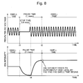
- the amplitude of the radio-frequency voltage may be temporarily decreased to zero (i.e. to stop the application of the radio-frequency voltage), or to a sufficiently small magnitude at which the ion-focusing effect nearly disappears, in the pause time in order to eliminate or reduce the charge-up of another ion optical transport system placed on the rear side of the ion transport optical system concerned.
- the pre-quadrupole mass filter 12 is normally supplied with not only the direct-current voltage but also the same radio-frequency voltage as the one applied to the main quadrupole mass filter 13 in the subsequent stage. Accordingly, as shown in Fig. 8 , the application of the radio-frequency voltage is stopped during the "stop time" which is included in the pause time and which corresponds to the voltage polarity reversal time in the previous embodiment. This causes the ion-focusing effect within the space in the pre-quadrupole mass filter 12 to disappear, and allows the ions to disperse, so that the ions cannot pass through the pre-quadrupole mass filter 12.
- the ions are bound by that field and tend to accumulate at a step of the direct-current potential which is formed between the pre-quadrupole mass filter 12 and the main quadrupole mass filter 13. Those ions easily come in contact with the support structure for the main quadrupole mass filter 13 (or other components) and cause a charge-up.
- the length of time to stop the application of the radio-frequency voltage or decrease its amplitude to such an extent that the ion-focusing effect virtually disappears should preferably be changed according to the length of the pause time.
- the present invention is applied in a normal type of quadrupole mass filter.
- the present invention can also be applied in a tandem quadrupole mass spectrometer having front and rear quadrupole mass filters with a collision cell in between.
- the operation of reversing the polarity of the direct-current voltage applied to the ion transport optical system or stopping the application of the radio-frequency voltage can be performed in the pause time which is assigned for switching the mass-to-charge ratios of the ions to be selected by the front and rear quadrupole mass filters (the precursor ion and product ion) in an MRM measurement (not the SIM measurement).
Landscapes
- Chemical & Material Sciences (AREA)
- Analytical Chemistry (AREA)
- Other Investigation Or Analysis Of Materials By Electrical Means (AREA)
- Electron Tubes For Measurement (AREA)
Applications Claiming Priority (1)
| Application Number | Priority Date | Filing Date | Title |
|---|---|---|---|
| PCT/JP2013/062914 WO2014181396A1 (ja) | 2013-05-08 | 2013-05-08 | 質量分析装置 |
Publications (3)
| Publication Number | Publication Date |
|---|---|
| EP2988317A1 true EP2988317A1 (de) | 2016-02-24 |
| EP2988317A4 EP2988317A4 (de) | 2016-08-17 |
| EP2988317B1 EP2988317B1 (de) | 2023-03-22 |
Family
ID=51866901
Family Applications (1)
| Application Number | Title | Priority Date | Filing Date |
|---|---|---|---|
| EP13884333.9A Active EP2988317B1 (de) | 2013-05-08 | 2013-05-08 | Massenspektrometer |
Country Status (5)
| Country | Link |
|---|---|
| US (1) | US9373487B2 (de) |
| EP (1) | EP2988317B1 (de) |
| JP (1) | JP6004098B2 (de) |
| CN (1) | CN105190831B (de) |
| WO (1) | WO2014181396A1 (de) |
Cited By (1)
| Publication number | Priority date | Publication date | Assignee | Title |
|---|---|---|---|---|
| WO2022223989A1 (en) * | 2021-04-23 | 2022-10-27 | Micromass Uk Limited | Method to reduce measurement bias |
Families Citing this family (24)
| Publication number | Priority date | Publication date | Assignee | Title |
|---|---|---|---|---|
| US10229822B2 (en) * | 2014-10-20 | 2019-03-12 | Shimadzu Corporation | Mass spectrometer with high-voltage power source |
| GB2534569A (en) * | 2015-01-27 | 2016-08-03 | Shimadzu Corp | Method of controlling a DC power supply |
| US10229823B2 (en) * | 2015-08-06 | 2019-03-12 | Shimadzu Corporation | Mass spectrometer |
| CN105225916B (zh) * | 2015-09-02 | 2017-06-23 | 上海新漫传感技术研究发展有限公司 | 实现单管离子迁移谱仪同时检测正负离子高压电源及方法 |
| JP2017054737A (ja) * | 2015-09-10 | 2017-03-16 | 株式会社東芝 | 質量分析装置および質量分析方法 |
| GB2544959B (en) * | 2015-09-17 | 2019-06-05 | Thermo Fisher Scient Bremen Gmbh | Mass spectrometer |
| US9741552B2 (en) * | 2015-12-22 | 2017-08-22 | Bruker Daltonics, Inc. | Triple quadrupole mass spectrometry coupled to trapped ion mobility separation |
| US10475635B2 (en) * | 2016-03-18 | 2019-11-12 | Shimadzu Corporation | Voltage application method, voltage application device, and time-of-flight mass spectrometer |
| CN110720133B (zh) * | 2017-06-29 | 2022-05-06 | 株式会社岛津制作所 | 四极杆质谱分析装置 |
| GB201710691D0 (en) * | 2017-07-04 | 2017-08-16 | Ge Healthcare Bio Sciences Ab | Method in bioprocess purification system |
| JP6927432B2 (ja) * | 2018-05-31 | 2021-09-01 | 株式会社島津製作所 | 質量分析装置 |
| WO2019229942A1 (ja) * | 2018-05-31 | 2019-12-05 | 株式会社島津製作所 | 飛行時間型質量分析装置 |
| WO2019229945A1 (ja) * | 2018-05-31 | 2019-12-05 | 株式会社島津製作所 | 質量分析装置 |
| JP6954465B2 (ja) | 2018-06-01 | 2021-10-27 | 株式会社島津製作所 | 四重極マスフィルタおよび分析装置 |
| CN112640034B (zh) * | 2018-09-06 | 2024-10-11 | 株式会社岛津制作所 | 四极质量分析装置 |
| GB2583092B (en) | 2019-04-15 | 2021-09-22 | Thermo Fisher Scient Bremen Gmbh | Mass spectrometer having improved quadrupole robustness |
| GB201907332D0 (en) | 2019-05-24 | 2019-07-10 | Micromass Ltd | Mass filter having reduced contamination |
| JP7207266B2 (ja) * | 2019-11-05 | 2023-01-18 | 株式会社島津製作所 | 質量分析装置 |
| GB202013325D0 (en) * | 2020-08-26 | 2020-10-07 | Micromass Ltd | System for determining the cleanliness of mass spectrometer ion optics |
| JP7480364B2 (ja) * | 2021-01-22 | 2024-05-09 | 株式会社日立ハイテク | 質量分析装置とその制御方法 |
| JP7775892B2 (ja) * | 2021-11-16 | 2025-11-26 | 株式会社島津製作所 | 質量分析装置およびその制御方法 |
| WO2023105912A1 (ja) * | 2021-12-10 | 2023-06-15 | 株式会社日立ハイテク | 質量分析装置の制御方法、質量分析装置 |
| US12119213B2 (en) | 2022-08-09 | 2024-10-15 | Nanjing Qlife Medical Technology Co., Ltd. | Power supply device for triple quadrupole mass spectrometer |
| WO2025154225A1 (ja) * | 2024-01-18 | 2025-07-24 | 株式会社島津製作所 | 質量分析装置および質量分析装置を制御する方法 |
Family Cites Families (10)
| Publication number | Priority date | Publication date | Assignee | Title |
|---|---|---|---|---|
| US4885500A (en) * | 1986-11-19 | 1989-12-05 | Hewlett-Packard Company | Quartz quadrupole for mass filter |
| GB8703012D0 (en) * | 1987-02-10 | 1987-03-18 | Vg Instr Group | Secondary ion mass spectrometer |
| US5298745A (en) * | 1992-12-02 | 1994-03-29 | Hewlett-Packard Company | Multilayer multipole |
| JPH087830A (ja) | 1994-06-24 | 1996-01-12 | Shimadzu Corp | 大気圧イオン化質量分析装置 |
| JP3830344B2 (ja) * | 2000-10-10 | 2006-10-04 | 日本電子株式会社 | 垂直加速型飛行時間型質量分析装置 |
| JP4037797B2 (ja) * | 2003-06-05 | 2008-01-23 | 日本電子株式会社 | 飛行時間型質量分析装置 |
| WO2009095952A1 (ja) * | 2008-01-30 | 2009-08-06 | Shimadzu Corporation | Ms/ms型質量分析装置 |
| JP5083160B2 (ja) * | 2008-10-06 | 2012-11-28 | 株式会社島津製作所 | 四重極型質量分析装置 |
| WO2011125218A1 (ja) * | 2010-04-09 | 2011-10-13 | 株式会社島津製作所 | 四重極型質量分析装置 |
| US8969797B2 (en) * | 2012-10-28 | 2015-03-03 | Shimadzu Corporation | MS/MS type mass spectrometer |
-
2013
- 2013-05-08 EP EP13884333.9A patent/EP2988317B1/de active Active
- 2013-05-08 CN CN201380076420.1A patent/CN105190831B/zh active Active
- 2013-05-08 WO PCT/JP2013/062914 patent/WO2014181396A1/ja not_active Ceased
- 2013-05-08 JP JP2015515666A patent/JP6004098B2/ja active Active
- 2013-05-08 US US14/889,605 patent/US9373487B2/en active Active
Cited By (3)
| Publication number | Priority date | Publication date | Assignee | Title |
|---|---|---|---|---|
| WO2022223989A1 (en) * | 2021-04-23 | 2022-10-27 | Micromass Uk Limited | Method to reduce measurement bias |
| GB2608490A (en) * | 2021-04-23 | 2023-01-04 | Micromass Ltd | Method to reduce measurement bias |
| GB2608490B (en) * | 2021-04-23 | 2024-06-12 | Micromass Ltd | Method to reduce measurement bias |
Also Published As
| Publication number | Publication date |
|---|---|
| US9373487B2 (en) | 2016-06-21 |
| EP2988317B1 (de) | 2023-03-22 |
| CN105190831A (zh) | 2015-12-23 |
| JPWO2014181396A1 (ja) | 2017-02-23 |
| EP2988317A4 (de) | 2016-08-17 |
| JP6004098B2 (ja) | 2016-10-05 |
| WO2014181396A1 (ja) | 2014-11-13 |
| US20160118235A1 (en) | 2016-04-28 |
| CN105190831B (zh) | 2017-03-08 |
Similar Documents
| Publication | Publication Date | Title |
|---|---|---|
| US9373487B2 (en) | Mass spectrometer | |
| US9029763B2 (en) | Ion deflection in time-of-flight mass spectrometry | |
| JP3670584B2 (ja) | イオントラップ質量分析装置用パルス型イオン源 | |
| CA2961183C (en) | Mass spectrometer | |
| JP6305543B2 (ja) | 標的化した質量分析 | |
| EP3059756A1 (de) | Ionisierungsvorrichtung | |
| JP5792155B2 (ja) | イオン移動度に対するイオン光学ドレイン | |
| US6707033B2 (en) | Mass spectrometer | |
| JP7210536B2 (ja) | 電子イオン化源からのイオンの移動 | |
| JPH11167895A (ja) | 質量分析装置および質量分装置におけるダイナミックレンジを改善する方法 | |
| EP2789007B1 (de) | Systeme, vorrichtungen und verfahren zur probenanalyse mittels massenspektrometrie | |
| WO2017068729A1 (ja) | 飛行時間型質量分析装置 | |
| US9035244B2 (en) | Automatic gain control with defocusing lens | |
| US10332733B2 (en) | Tandem mass spectrometer | |
| WO2015092862A1 (ja) | 質量分析装置及び質量分析方法 | |
| JP5426571B2 (ja) | イオン電荷蓄積装置の電荷制御 | |
| JP6006322B2 (ja) | 質量分析装置および質量分離装置 | |
| JP7534958B2 (ja) | Tof質量分析器の抽出領域内でイオンパケットを動的に濃縮する | |
| JP4248540B2 (ja) | 質量分析装置およびこれを用いる計測システム | |
| CN117321730A (zh) | 用于使用ms灵敏度改进技术的按需/动态实施定量的增益校准 | |
| JP6128235B2 (ja) | イオン移動度分析装置及び質量分析装置 | |
| US20260002905A1 (en) | Hybridized ion pre-separation for mass spectrometry | |
| JP2007528577A (ja) | 改良型イオン選択ユニットを有する質量分析器 |
Legal Events
| Date | Code | Title | Description |
|---|---|---|---|
| PUAI | Public reference made under article 153(3) epc to a published international application that has entered the european phase |
Free format text: ORIGINAL CODE: 0009012 |
|
| 17P | Request for examination filed |
Effective date: 20151117 |
|
| AK | Designated contracting states |
Kind code of ref document: A1 Designated state(s): AL AT BE BG CH CY CZ DE DK EE ES FI FR GB GR HR HU IE IS IT LI LT LU LV MC MK MT NL NO PL PT RO RS SE SI SK SM TR |
|
| AX | Request for extension of the european patent |
Extension state: BA ME |
|
| RIC1 | Information provided on ipc code assigned before grant |
Ipc: H01J 49/42 20060101AFI20160322BHEP Ipc: H01J 49/02 20060101ALI20160322BHEP Ipc: H01J 49/00 20060101ALI20160322BHEP |
|
| A4 | Supplementary search report drawn up and despatched |
Effective date: 20160720 |
|
| DAX | Request for extension of the european patent (deleted) | ||
| RIC1 | Information provided on ipc code assigned before grant |
Ipc: H01J 49/00 20060101ALI20160714BHEP Ipc: H01J 49/42 20060101AFI20160714BHEP Ipc: H01J 49/02 20060101ALI20160714BHEP |
|
| STAA | Information on the status of an ep patent application or granted ep patent |
Free format text: STATUS: EXAMINATION IS IN PROGRESS |
|
| 17Q | First examination report despatched |
Effective date: 20190116 |
|
| GRAP | Despatch of communication of intention to grant a patent |
Free format text: ORIGINAL CODE: EPIDOSNIGR1 |
|
| STAA | Information on the status of an ep patent application or granted ep patent |
Free format text: STATUS: GRANT OF PATENT IS INTENDED |
|
| INTG | Intention to grant announced |
Effective date: 20220915 |
|
| GRAS | Grant fee paid |
Free format text: ORIGINAL CODE: EPIDOSNIGR3 |
|
| GRAA | (expected) grant |
Free format text: ORIGINAL CODE: 0009210 |
|
| STAA | Information on the status of an ep patent application or granted ep patent |
Free format text: STATUS: THE PATENT HAS BEEN GRANTED |
|
| AK | Designated contracting states |
Kind code of ref document: B1 Designated state(s): AL AT BE BG CH CY CZ DE DK EE ES FI FR GB GR HR HU IE IS IT LI LT LU LV MC MK MT NL NO PL PT RO RS SE SI SK SM TR |
|
| REG | Reference to a national code |
Ref country code: GB Ref legal event code: FG4D |
|
| REG | Reference to a national code |
Ref country code: CH Ref legal event code: EP |
|
| REG | Reference to a national code |
Ref country code: DE Ref legal event code: R096 Ref document number: 602013083487 Country of ref document: DE |
|
| REG | Reference to a national code |
Ref country code: IE Ref legal event code: FG4D |
|
| REG | Reference to a national code |
Ref country code: AT Ref legal event code: REF Ref document number: 1555809 Country of ref document: AT Kind code of ref document: T Effective date: 20230415 |
|
| REG | Reference to a national code |
Ref country code: LT Ref legal event code: MG9D |
|
| REG | Reference to a national code |
Ref country code: NL Ref legal event code: MP Effective date: 20230322 |
|
| PG25 | Lapsed in a contracting state [announced via postgrant information from national office to epo] |
Ref country code: RS Free format text: LAPSE BECAUSE OF FAILURE TO SUBMIT A TRANSLATION OF THE DESCRIPTION OR TO PAY THE FEE WITHIN THE PRESCRIBED TIME-LIMIT Effective date: 20230322 Ref country code: NO Free format text: LAPSE BECAUSE OF FAILURE TO SUBMIT A TRANSLATION OF THE DESCRIPTION OR TO PAY THE FEE WITHIN THE PRESCRIBED TIME-LIMIT Effective date: 20230622 Ref country code: LV Free format text: LAPSE BECAUSE OF FAILURE TO SUBMIT A TRANSLATION OF THE DESCRIPTION OR TO PAY THE FEE WITHIN THE PRESCRIBED TIME-LIMIT Effective date: 20230322 Ref country code: LT Free format text: LAPSE BECAUSE OF FAILURE TO SUBMIT A TRANSLATION OF THE DESCRIPTION OR TO PAY THE FEE WITHIN THE PRESCRIBED TIME-LIMIT Effective date: 20230322 Ref country code: HR Free format text: LAPSE BECAUSE OF FAILURE TO SUBMIT A TRANSLATION OF THE DESCRIPTION OR TO PAY THE FEE WITHIN THE PRESCRIBED TIME-LIMIT Effective date: 20230322 |
|
| REG | Reference to a national code |
Ref country code: AT Ref legal event code: MK05 Ref document number: 1555809 Country of ref document: AT Kind code of ref document: T Effective date: 20230322 |
|
| PG25 | Lapsed in a contracting state [announced via postgrant information from national office to epo] |
Ref country code: SE Free format text: LAPSE BECAUSE OF FAILURE TO SUBMIT A TRANSLATION OF THE DESCRIPTION OR TO PAY THE FEE WITHIN THE PRESCRIBED TIME-LIMIT Effective date: 20230322 Ref country code: NL Free format text: LAPSE BECAUSE OF FAILURE TO SUBMIT A TRANSLATION OF THE DESCRIPTION OR TO PAY THE FEE WITHIN THE PRESCRIBED TIME-LIMIT Effective date: 20230322 Ref country code: GR Free format text: LAPSE BECAUSE OF FAILURE TO SUBMIT A TRANSLATION OF THE DESCRIPTION OR TO PAY THE FEE WITHIN THE PRESCRIBED TIME-LIMIT Effective date: 20230623 Ref country code: FI Free format text: LAPSE BECAUSE OF FAILURE TO SUBMIT A TRANSLATION OF THE DESCRIPTION OR TO PAY THE FEE WITHIN THE PRESCRIBED TIME-LIMIT Effective date: 20230322 |
|
| PG25 | Lapsed in a contracting state [announced via postgrant information from national office to epo] |
Ref country code: SM Free format text: LAPSE BECAUSE OF FAILURE TO SUBMIT A TRANSLATION OF THE DESCRIPTION OR TO PAY THE FEE WITHIN THE PRESCRIBED TIME-LIMIT Effective date: 20230322 Ref country code: RO Free format text: LAPSE BECAUSE OF FAILURE TO SUBMIT A TRANSLATION OF THE DESCRIPTION OR TO PAY THE FEE WITHIN THE PRESCRIBED TIME-LIMIT Effective date: 20230322 Ref country code: PT Free format text: LAPSE BECAUSE OF FAILURE TO SUBMIT A TRANSLATION OF THE DESCRIPTION OR TO PAY THE FEE WITHIN THE PRESCRIBED TIME-LIMIT Effective date: 20230724 Ref country code: ES Free format text: LAPSE BECAUSE OF FAILURE TO SUBMIT A TRANSLATION OF THE DESCRIPTION OR TO PAY THE FEE WITHIN THE PRESCRIBED TIME-LIMIT Effective date: 20230322 Ref country code: EE Free format text: LAPSE BECAUSE OF FAILURE TO SUBMIT A TRANSLATION OF THE DESCRIPTION OR TO PAY THE FEE WITHIN THE PRESCRIBED TIME-LIMIT Effective date: 20230322 Ref country code: AT Free format text: LAPSE BECAUSE OF FAILURE TO SUBMIT A TRANSLATION OF THE DESCRIPTION OR TO PAY THE FEE WITHIN THE PRESCRIBED TIME-LIMIT Effective date: 20230322 |
|
| PG25 | Lapsed in a contracting state [announced via postgrant information from national office to epo] |
Ref country code: SK Free format text: LAPSE BECAUSE OF FAILURE TO SUBMIT A TRANSLATION OF THE DESCRIPTION OR TO PAY THE FEE WITHIN THE PRESCRIBED TIME-LIMIT Effective date: 20230322 Ref country code: PL Free format text: LAPSE BECAUSE OF FAILURE TO SUBMIT A TRANSLATION OF THE DESCRIPTION OR TO PAY THE FEE WITHIN THE PRESCRIBED TIME-LIMIT Effective date: 20230322 Ref country code: IS Free format text: LAPSE BECAUSE OF FAILURE TO SUBMIT A TRANSLATION OF THE DESCRIPTION OR TO PAY THE FEE WITHIN THE PRESCRIBED TIME-LIMIT Effective date: 20230722 |
|
| REG | Reference to a national code |
Ref country code: CH Ref legal event code: PL |
|
| REG | Reference to a national code |
Ref country code: DE Ref legal event code: R097 Ref document number: 602013083487 Country of ref document: DE |
|
| PG25 | Lapsed in a contracting state [announced via postgrant information from national office to epo] |
Ref country code: MC Free format text: LAPSE BECAUSE OF FAILURE TO SUBMIT A TRANSLATION OF THE DESCRIPTION OR TO PAY THE FEE WITHIN THE PRESCRIBED TIME-LIMIT Effective date: 20230322 |
|
| PLBE | No opposition filed within time limit |
Free format text: ORIGINAL CODE: 0009261 |
|
| STAA | Information on the status of an ep patent application or granted ep patent |
Free format text: STATUS: NO OPPOSITION FILED WITHIN TIME LIMIT |
|
| REG | Reference to a national code |
Ref country code: BE Ref legal event code: MM Effective date: 20230531 |
|
| PG25 | Lapsed in a contracting state [announced via postgrant information from national office to epo] |
Ref country code: SI Free format text: LAPSE BECAUSE OF FAILURE TO SUBMIT A TRANSLATION OF THE DESCRIPTION OR TO PAY THE FEE WITHIN THE PRESCRIBED TIME-LIMIT Effective date: 20230322 Ref country code: MC Free format text: LAPSE BECAUSE OF FAILURE TO SUBMIT A TRANSLATION OF THE DESCRIPTION OR TO PAY THE FEE WITHIN THE PRESCRIBED TIME-LIMIT Effective date: 20230322 Ref country code: LU Free format text: LAPSE BECAUSE OF NON-PAYMENT OF DUE FEES Effective date: 20230508 Ref country code: LI Free format text: LAPSE BECAUSE OF NON-PAYMENT OF DUE FEES Effective date: 20230531 Ref country code: DK Free format text: LAPSE BECAUSE OF FAILURE TO SUBMIT A TRANSLATION OF THE DESCRIPTION OR TO PAY THE FEE WITHIN THE PRESCRIBED TIME-LIMIT Effective date: 20230322 Ref country code: CZ Free format text: LAPSE BECAUSE OF FAILURE TO SUBMIT A TRANSLATION OF THE DESCRIPTION OR TO PAY THE FEE WITHIN THE PRESCRIBED TIME-LIMIT Effective date: 20230322 Ref country code: CH Free format text: LAPSE BECAUSE OF NON-PAYMENT OF DUE FEES Effective date: 20230531 |
|
| 26N | No opposition filed |
Effective date: 20240102 |
|
| REG | Reference to a national code |
Ref country code: IE Ref legal event code: MM4A |
|
| PG25 | Lapsed in a contracting state [announced via postgrant information from national office to epo] |
Ref country code: IE Free format text: LAPSE BECAUSE OF NON-PAYMENT OF DUE FEES Effective date: 20230508 |
|
| PG25 | Lapsed in a contracting state [announced via postgrant information from national office to epo] |
Ref country code: IE Free format text: LAPSE BECAUSE OF NON-PAYMENT OF DUE FEES Effective date: 20230508 |
|
| PG25 | Lapsed in a contracting state [announced via postgrant information from national office to epo] |
Ref country code: IT Free format text: LAPSE BECAUSE OF FAILURE TO SUBMIT A TRANSLATION OF THE DESCRIPTION OR TO PAY THE FEE WITHIN THE PRESCRIBED TIME-LIMIT Effective date: 20230322 Ref country code: FR Free format text: LAPSE BECAUSE OF NON-PAYMENT OF DUE FEES Effective date: 20230522 Ref country code: BE Free format text: LAPSE BECAUSE OF NON-PAYMENT OF DUE FEES Effective date: 20230531 |
|
| PG25 | Lapsed in a contracting state [announced via postgrant information from national office to epo] |
Ref country code: BG Free format text: LAPSE BECAUSE OF FAILURE TO SUBMIT A TRANSLATION OF THE DESCRIPTION OR TO PAY THE FEE WITHIN THE PRESCRIBED TIME-LIMIT Effective date: 20230322 |
|
| PG25 | Lapsed in a contracting state [announced via postgrant information from national office to epo] |
Ref country code: BG Free format text: LAPSE BECAUSE OF FAILURE TO SUBMIT A TRANSLATION OF THE DESCRIPTION OR TO PAY THE FEE WITHIN THE PRESCRIBED TIME-LIMIT Effective date: 20230322 |
|
| PGFP | Annual fee paid to national office [announced via postgrant information from national office to epo] |
Ref country code: DE Payment date: 20250402 Year of fee payment: 13 |
|
| PG25 | Lapsed in a contracting state [announced via postgrant information from national office to epo] |
Ref country code: CY Free format text: LAPSE BECAUSE OF FAILURE TO SUBMIT A TRANSLATION OF THE DESCRIPTION OR TO PAY THE FEE WITHIN THE PRESCRIBED TIME-LIMIT; INVALID AB INITIO Effective date: 20130508 |
|
| PG25 | Lapsed in a contracting state [announced via postgrant information from national office to epo] |
Ref country code: HU Free format text: LAPSE BECAUSE OF FAILURE TO SUBMIT A TRANSLATION OF THE DESCRIPTION OR TO PAY THE FEE WITHIN THE PRESCRIBED TIME-LIMIT; INVALID AB INITIO Effective date: 20130508 |
|
| PG25 | Lapsed in a contracting state [announced via postgrant information from national office to epo] |
Ref country code: TR Free format text: LAPSE BECAUSE OF FAILURE TO SUBMIT A TRANSLATION OF THE DESCRIPTION OR TO PAY THE FEE WITHIN THE PRESCRIBED TIME-LIMIT Effective date: 20230322 |
|
| PGFP | Annual fee paid to national office [announced via postgrant information from national office to epo] |
Ref country code: GB Payment date: 20260323 Year of fee payment: 14 |