EP2988529A1 - Frequence de division adaptative dans appareils d'aide auditive - Google Patents
Frequence de division adaptative dans appareils d'aide auditive Download PDFInfo
- Publication number
- EP2988529A1 EP2988529A1 EP15179351.0A EP15179351A EP2988529A1 EP 2988529 A1 EP2988529 A1 EP 2988529A1 EP 15179351 A EP15179351 A EP 15179351A EP 2988529 A1 EP2988529 A1 EP 2988529A1
- Authority
- EP
- European Patent Office
- Prior art keywords
- frequency
- transfer function
- division frequency
- division
- feedback
- Prior art date
- Legal status (The legal status is an assumption and is not a legal conclusion. Google has not performed a legal analysis and makes no representation as to the accuracy of the status listed.)
- Granted
Links
Images


Classifications
-
- H—ELECTRICITY
- H04—ELECTRIC COMMUNICATION TECHNIQUE
- H04R—LOUDSPEAKERS, MICROPHONES, GRAMOPHONE PICK-UPS OR LIKE ACOUSTIC ELECTROMECHANICAL TRANSDUCERS; ELECTRIC HEARING AIDS; PUBLIC ADDRESS SYSTEMS
- H04R25/00—Electric hearing aids
- H04R25/45—Prevention of acoustic reaction, i.e. acoustic oscillatory feedback
- H04R25/453—Prevention of acoustic reaction, i.e. acoustic oscillatory feedback electronically
-
- H—ELECTRICITY
- H04—ELECTRIC COMMUNICATION TECHNIQUE
- H04R—LOUDSPEAKERS, MICROPHONES, GRAMOPHONE PICK-UPS OR LIKE ACOUSTIC ELECTROMECHANICAL TRANSDUCERS; ELECTRIC HEARING AIDS; PUBLIC ADDRESS SYSTEMS
- H04R25/00—Electric hearing aids
- H04R25/55—Electric hearing aids using an external connection, either wireless or wired
- H04R25/554—Electric hearing aids using an external connection, either wireless or wired using a wireless connection, e.g. between microphone and amplifier or using Tcoils
-
- H—ELECTRICITY
- H04—ELECTRIC COMMUNICATION TECHNIQUE
- H04R—LOUDSPEAKERS, MICROPHONES, GRAMOPHONE PICK-UPS OR LIKE ACOUSTIC ELECTROMECHANICAL TRANSDUCERS; ELECTRIC HEARING AIDS; PUBLIC ADDRESS SYSTEMS
- H04R2430/00—Signal processing covered by H04R, not provided for in its groups
- H04R2430/03—Synergistic effects of band splitting and sub-band processing
-
- H—ELECTRICITY
- H04—ELECTRIC COMMUNICATION TECHNIQUE
- H04R—LOUDSPEAKERS, MICROPHONES, GRAMOPHONE PICK-UPS OR LIKE ACOUSTIC ELECTROMECHANICAL TRANSDUCERS; ELECTRIC HEARING AIDS; PUBLIC ADDRESS SYSTEMS
- H04R25/00—Electric hearing aids
- H04R25/35—Electric hearing aids using translation techniques
- H04R25/353—Frequency, e.g. frequency shift or compression
Definitions
- the invention relates to a method for suppressing acoustic feedback in a hearing aid, wherein a pitch frequency between a first frequency range with feedback suppression and a second frequency range is adapted without feedback suppression, and an apparatus and a system for carrying out the method.
- Hearing aids are portable hearing aids that are used to care for the hearing impaired.
- different types of hearing aids such as behind-the-ear hearing aids (BTE), hearing aid with external receiver (RIC: receiver in the canal) and in-the-ear hearing aids (ITE), e.g. Concha hearing aids or canal hearing aids (ITE, CIC).
- BTE behind-the-ear hearing aids
- RIC hearing aid with external receiver
- ITE in-the-ear hearing aids
- ITE in-the-ear hearing aids
- ITE in-the-ear hearing aids
- ITE concha hearing aids or canal hearing aids
- the hearing aids listed by way of example are worn on the outer ear or in the ear canal.
- bone conduction hearing aids, implantable or vibrotactile hearing aids are also available on the market. The stimulation of the damaged hearing takes place either mechanically or electrically.
- Hearing aids have in principle as essential components an input transducer, an amplifier and an output transducer.
- the input transducer is usually an acoustoelectric transducer, z. As a microphone, and / or an electromagnetic receiver, for. B. an induction coil.
- the output transducer is usually used as an electroacoustic transducer, z. As miniature speaker, or as an electromechanical transducer, z. B. bone conduction, realized.
- the amplifier is usually integrated in a signal processing device.
- the power is usually supplied by a battery or a rechargeable battery.
- a frequency shift or a time-variable phase shift (eg a phase modulation) of the receiver signal has an advantageous effect on the quality of the estimated feedback pulse response.
- a superimposition of these two signal components comes about for two reasons: 1. Signal components emitted directly from the sound source are superimposed acoustically in front of the eardrum with signal components emitted by the listener. 2. Due to the finite edge steepness of the filters, which realize the pitch frequency, above which the signal is frequency-shifted and / or phase-modulated, signal components are superimposed electrically.
- this object is achieved by a method according to claim 1, as well as a device according to claim 8 and a system according to claim 11
- the inventive method relates to a method for suppressing an acoustic feedback in a hearing aid.
- the hearing aid has an acousto-electric input transducer, signal processing and an electro-acoustic output transducer.
- the method according to the invention has the following steps.
- an acoustic frequency range transmitted by the hearing aid is divided into a first frequency range above a first division frequency and a second frequency range below the first division frequency. It is conceivable that in the real implementation of the frequency division by filters due to finite edge steepness an overlap region is given, for example, 10 Hz, 50 Hz, 100 Hz or 200Hz may be and in which an amplitude of a signal from the respective adjacent frequency range, for example by 6 dB, 12 dB or 18 dB is attenuated.
- a first transfer function of a feedback loop via the electro-acoustic output transducer, an acoustic feedback path, the acousto-electric input transducer and the signal processing in the first frequency range is estimated.
- the estimated first transfer function is an illustration of a real transfer function resulting for the feedback loop from the acoustic environment (i.e., the estimated feedback impulse response) and the hearing aid.
- a frequency shift and / or phase modulation is also carried out in a predetermined frequency range below the division frequency, for example at a fixed distance of 50 Hz, 100 Hz or 200 Hz or in a predetermined dependence of the pitch frequency.
- the first transfer function is evaluated as to whether the behavior of the first transfer function in the vicinity of the first division frequency is to be expected to exceed a predetermined limit value by the real transfer function.
- Various ways to evaluate the first transfer function are given in the dependent claims.
- the first division frequency is increased to a second division frequency such that all values of a gain of the first transfer function of the feedback loop become smaller for frequencies smaller than the increased second division frequency as the predetermined limit are.
- the second division frequency is increased at most to a value below a cut-off frequency at which the gain of the closed loop does not exceed the limit.
- the first division frequency is reduced to a second division frequency if, in the vicinity of the first division frequency, exceeding the predetermined limit value by the real transfer function is to be expected.
- the second division frequency is reduced to a value below a cutoff frequency at which the gain of the feedback loop is expected to be less than the limit.
- the insertion frequency may be, for example, a fixed amount of, for example, 50 Hz, 100 Hz or 200 Hz below the second division frequency, or may assume a value of the second division frequency reduced by linear or other predetermined factor.
- the method according to the invention adapts the pitch frequency between a first frequency range, in which a phase or frequency shift is necessary to prevent feedback, and a second frequency range, in which this is not required, depending on the feedback path.
- the frequency range is minimized in which occur due to the phase shift interfering artifacts.
- the method also makes it possible to derive an evaluation or prediction of the real transfer function for a frequency range below the division frequency from an estimate of the first transfer function in the first frequency range. This is particularly advantageous, since an estimation is usually carried out only in a frequency range which is endangered by feedback above a cutoff frequency Among other things, to conserve resources of the hearing aid.
- the invention also relates to a device for suppressing acoustic feedback in a hearing aid.
- the hearing aid has an acousto-electric input transducer, signal processing and an electro-acoustic output transducer.
- the device is in signal communication with the hearing aid, in particular, the device receives information from the hearing aid to a signal received via the microphone and a signal output to the listener.
- the device is designed to divide an acoustic frequency range to be transmitted by the hearing aid into a first frequency range above a first pitch frequency and a second frequency range below the first pitch frequency.
- the apparatus is further configured to estimate a first transfer function of a feedback loop via the electroacoustic output transducer, an acoustic feedback path, the acousto-electric input transducer, and the signal processing in the first frequency range as an illustration of a real transfer function across the feedback loop.
- the device is also designed to evaluate the first transfer function as to whether the behavior of the first transfer function in the vicinity of the first division frequency is to be expected to exceed a predetermined limit value by the real transfer function.
- the device is designed, when in the environment of the first division frequency exceeding a predetermined limit value by the real transfer function is not expected to increase the first division frequency far enough to a second division frequency, that all values of a gain of the first transfer function for frequencies smaller when the second division frequency is smaller than the predetermined limit value.
- the device is designed, if it is to be expected in the vicinity of the first division frequency exceeding a predetermined limit value by the real transfer function, to reduce the first division frequency to a second division frequency.
- the device is designed to set in the hearing aid a phase or frequency change for feedback suppression in the signal processing only above an insertion frequency in response to the second division frequency.
- the invention relates to an inventive system of a hearing aid and a device according to the invention.
- the device is part of the hearing aid, for example, implemented as a separate unit or as part of the signal processing of the hearing aid.
- the device is an external device and is implemented in a separate unit such as a remote control, a converter or even by an application on a smartphone.
- the device according to the invention and the system according to the invention share the advantages of the method according to the invention.
- the behavior of a real transfer function of the environment and the hearing aid in an environment of the pitch frequency is similar to the behavior of the estimated first transfer function above the first division frequency, the behavior of the real transfer function and thus the feedback behavior of the hearing aid for Frequencies below the first division frequency are predicted.
- the first transfer function increases above the first division frequency, it can be expected and concluded that the real transfer function also exceeds the limit value below the first division frequency in a frequency range.
- the limit value is not exceeded by the real transfer function even below the first division function. Accordingly, it is then possible to shift the first division frequency by this frequency range down to a second division frequency.
- a second transfer function of a feedback loop in a third frequency range below the first division frequency is determined as a function of the first transfer function of the closed feedback loop.
- the determining may comprise deriving the second transfer function from the first transfer function, for example by assuming a value of the lowest frequency of the first transfer function as a constant value of the second transfer function for the third frequency range or a part thereof or the second transfer function linearly or in another way the first transfer function is interpolated.
- the third frequency range is adjacent to the first frequency range Pitch frequency.
- the third frequency range comprises only a part of the second frequency range, for example a half, a third, a quarter or a tenth of the bandwidth of the second frequency range.
- Determining a second transfer function by means of interpolation advantageously makes it possible to more accurately predict a real transfer function of the acoustic environment and of the hearing aid even with more complex behavior and to determine the second division frequency even more reliably.
- the predetermined limit value of a gain of the first or second transfer function is 0 dB minus a stability distance.
- the method proceeds by estimating a first transfer function of a closed feedback loop (S20).
- the method according to the invention is advantageously able to adapt to changing conditions such as acoustic environment or changed seat of the hearing aid.
- the division frequency is greater than 1 kHz.
- the method according to the invention is advantageously limited to a frequency range above 1 kHz in order to avoid artifacts in the particularly sensitive range of the fundamental frequencies of the speech and to save resources in the signal processing of the hearing aid.
- the pitch frequency is less than 2 kHz.
- the method according to the invention is based, in particular, on the knowledge that below 2 kHz there is a correlation between the behavior of a feedback path at different frequencies. It is therefore possible, in particular in frequency ranges below 2 kHz, to conclude from estimated characteristics of a feedback path at one frequency to the characteristics of the feedback path at another frequency.
- the method according to the invention uses this knowledge to advantageously determine from the estimated first transfer function above the division frequency a second transfer function in a third frequency range below the division frequency, without having to estimate it costly.
- Fig. 1 shows a basic structure of a hearing aid according to the invention 100.
- a hearing aid housing 1 for carrying behind the ear are one or more microphones, also referred to as acousto-electrical converter 2, incorporated for receiving the sound or acoustic signals from the environment.
- the microphones 2 are acousto-electrical converters 2 for converting the sound into first electrical audio signals.
- the output signal of the signal processing device 3 is transmitted to a loudspeaker or receiver 4, which outputs an acoustic signal.
- the sound is optionally transmitted via a sound tube, which is fixed with an earmold in the ear canal, to the eardrum of the device carrier. But it is also another electro-mechanical transducer conceivable, such as a bone conduction.
- the power supply of the hearing aid and in particular the signal processing device 3 is effected by a likewise integrated into the hearing aid housing 1 battery. 5
- the hearing aid device 100 furthermore has a device 6 according to the invention for suppressing acoustic feedback.
- This is in signal communication with the signal processing device 3 in order to acquire information about an acoustic signal received by the microphone 2 and a signal output to the receiver 4.
- the device 6 is able to influence the signal processing device 3 via the signal connection, for example to activate a phase shift in a frequency range or to change this frequency range.
- the function of the device 6 is implemented in the signal processing device 3, for example as circuits in an ASIC or as a function block in a signal processor.
- Fig. 2 shows the basic structure of a system 200 according to the invention, consisting of a hearing aid 100 and a separate device 6.
- the signal connection between the device 6 is preferably realized wirelessly, for example via an inductive coupling, as it is also used in binaural hearing aids for coupling.
- Conceivable are other electromagnetic transmissions with low energy consumption such as Bluetooth. Also conceivable are optical transmission or conducted transmission.
- the device 6 can be a dedicated device or even a multifunctional device such as a remote control, a media converter (for example, a Bluetooth induction loop) or a smartphone.
- a media converter for example, a Bluetooth induction loop
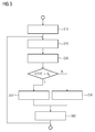
- Fig. 3 shows a schematic flow diagram of a method according to the invention.
- an acoustic frequency range transmitted by the hearing aid device 100 is split into a first frequency range FB1 above a first pitch frequency TF and a second frequency range FB2 below the first pitch frequency TF.
- This division can be done in the signal processing device 3 or in the device 6 itself.
- the first division frequency TF may be a predetermined value or may have resulted from previous steps.
- a first transfer function of a closed loop transfer function is estimated via the electro-acoustic output transducer, an acoustic feedback path, the acousto-electric input transducer and the signal processing in the first frequency range FB1.
- CLTF closed loop transfer function
- algorithms can be used for estimation which minimize an error between the real transmission or transfer function of the feedback loop via receiver 4, microphone 2 and signal processing 3 and a parameterized function and thus determine the parameters (for example LMS).
- This estimation function is usually part of a feedback suppression and therefore takes place only for a feedback-prone frequency range. According to the invention, this is the first frequency range FB1 above the first pitch frequency TF.
- the estimated transfer function is an approximate mapping of the real transfer function in the first frequency range FB1.
- the first transfer function is evaluated as to whether an exceeding of the predetermined limit value AG by the real transfer function is to be expected in an environment of the first division frequency TF.
- the first transfer function is a parameterized approximation function for the real transfer function in the feedback loop in the first frequency range FB1
- the real transfer function obeys certain mathematical and acoustic laws, so that values of the real transfer function for the first frequency range FB1 can also be used to deduce functional values in an adjacent frequency range FB2. According to the invention, therefore, the behavior of the real transfer function in an environment of the first division frequency TF is inferred from the values of the first estimated transfer function in the first frequency range FB1 in the step S30.
- an environment is to be understood as meaning a frequency range which can also extend to frequencies outside the first frequency range FB1, for example to frequencies below the first division frequency TF. These may be frequencies immediately below the pitch frequency TF, for example 20, 50 or 100 Hertz below.
- frequencies immediately below the pitch frequency TF for example 20, 50 or 100 Hertz below.
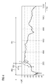
- a transfer function in Fig. 4 shows, but can also be assumed a decreasing behavior of the gain of the transfer function at a distance of up to one kilohertz.
- the first transfer function drops to the first division frequency TF, so can also for frequencies in a third frequency range FB3 below the first division frequency TF, a fall in the real transfer function can be assumed.
- the evaluation shows that the real transfer function does not exceed the predetermined limit value below the first division frequency TF up to a frequency spacing of 100, 200, 500 or even 1000 Hz.
- the real transfer function constantly maintains or at least does not exceed the value of the first transfer function directly at or above the first division frequency TF.
- a second transfer function of the closed feedback loop is determined in a third frequency range FB3 below the first division frequency TF as a function of the first transfer function of the closed feedback loop.
- the third frequency range FB3 is below the first pitch frequency TF. Below the first division frequency TF there is no estimate of the CLTF.
- a second transfer function below the division frequency TF for the third frequency range FB3 can be determined from the first transfer function.
- This determination can be carried out most simply by assuming for the second transfer function in a predetermined frequency range, for example the third frequency range FB3, a value of the first transfer function, eg the value at the lowest frequency for which it was estimated, as a constant function value.
- the determination may also be performed, for example, by linear or polynomial functions. Other functions are conceivable.
- the determination of a transfer function by means of these functions requires a significantly lower expenditure of computing power than the estimation by means of acoustic signals.
- the result of the determination is particularly close to a real transfer function, if the third frequency range FB3 is located directly below the first division frequency TF.
- the third frequency range FB3 does not directly adjoin the first pitch frequency TF.
- the third frequency range FB3 preferably comprises only a part of the second frequency range FB2.
- the first division frequency TF is increased to a second division frequency TF2 if, in an environment of the first division frequency TF, exceeding of the predetermined limit value AG by the real transfer function is not to be expected. This may be the case, for example, if the first transfer function drops to the first division frequency TF, ie the function values decrease with decreasing frequency. According to the exemplary transfer function of Fig. 4 however, it may already be sufficient if the function value of the first transfer function at the division frequency TF or in the immediate vicinity is smaller than the limit value AG of the amplification.
- the first division frequency TF may then be increased to a second division frequency TF2 such that all values of a gain of the first transfer function of a closed feedback loop for frequencies less than the increased second division frequency TF2 are less than the predetermined limit AG.
- the predetermined limit AG results from the fact that the total gain of the closed feedback loop, taking into account the phase angle, must be less than or equal to one.
- a safety margin is preferably provided in the selection of the predetermined limit value. This can be for example a distance of -2 dB, -3 dB or -6 dB.
- step S30 If a second transfer function was determined in step S30 for evaluation, then if all values of the particular second transfer function are smaller than a predetermined limit value AG, it is ensured that no feedback occurs below the previous first division frequency TF.
- the frequency value is increased until the value of the estimated first transfer function is greater than or equal to the predetermined limit value AG.
- the increased second division frequency TF2 is then the last preceding frequency value. In this way it is ensured that for all values below the increased second division frequency TF2 the conditions for a feedback are not given and therefore a feedback suppression with possible artifacts can be dispensed with.
- a step S50 if from the evaluation of step S30 exceeding the limit value AG by the real transfer function is to be expected, the first division frequency TF is lowered to a second division frequency TF2.
- the distance from pitch frequency TF2 to TF can advantageously follow the course of the exemplary transfer function of FIG Fig. 4 be removed.
- the cut-off frequency can be lowered by 100, 200, 500 or even 1000 Hz.
- the first division frequency TF can advantageously be reduced to a second division frequency TF2 such that all values of a gain of the second transfer function TF2 of a closed feedback loop for frequencies less than the reduced second division frequency TF2 are less than the predetermined threshold AG.
- a phase change for feedback suppression in the signal processing is applied only above an insertion frequency as a function of the second division frequency TF2.
- the insertion frequency may be, for example, a fixed amount of, for example, 50 Hz, 100 Hz, or 200 Hz below the second division frequency TF2, or may assume a value of the second division frequency TF2 reduced by linear or other predetermined factor. It is conceivable that the dependency reflects the sensitivity of the ear to artifacts and decreases in comparison with a distance linear to the pitch frequency TF or TF2.
- the method with the second division frequency TF2 is continued as a new output value with step S20, that is to say the first division frequency TF is set equal to the second division frequency TF2 and a new second division frequency TF2 'is determined by steps S20 to S50 ,
- the inventive method is able to adapt to changing acoustic conditions, be it one other room, other ambient noise or a changed seat of the hearing aid.
- Fig. 4 shows an exemplary estimated transfer function of a feedback path.
- the frequency f in Hz is plotted on the x-axis, and the amplification of an exemplary CLTF in dB on the y-axis.
- an estimate of the CLTF is made as part of a feedback suppression activated in this first frequency range FB1.
- the second frequency range FB2 below the pitch frequency TF there is no feedback suppression and therefore no estimation of the transfer function CLTF.
- K for correlation
- Fig. 5 shows a schematic representation in function blocks of a possible implementation of a hearing aid device or system according to the invention.
- a microphone 2 receives an audio signal, converts it into an electrical signal that is processed by a signal processing HP of the hearing aid according to the impairment of the hearing aid wearer and is output via a handset 4 to the ear of the wearer.
- Other components such as battery, housing or controls are in Fig. 5 not shown, but part of the hearing aid according to the invention.
- the audio signal of the microphone 2 is further divided into a first frequency range FB1 and a second frequency range FB2.
- This can be done by separate high and low pass filters or a simple filter bank.
- This is followed by an estimate of the transfer function in the first frequency range FB1 by means of a feedback control FBC (English: feed back controller).
- FBC feed back controller
- a phase or frequency distortion FD takes place in the first frequency range FB1 in order to take countermeasures against the feedback risk detected by the feedback control, by changing the phase or by frequency shifting.
- the feedback suppressor device 6 receives information from the feedback controller FBC via the estimated transfer function as well as from the signal processor HP via further signal changes in the hearing aid ,
- the device 6 is therefore able to determine directly from the estimated external transfer function a transfer function for a closed feedback loop CLTF for the first frequency range FB1, as well as according to the inventive idea based on the correlation between the first frequency range FB1 and second frequency range FB2 at least to determine a transfer function from the estimated transfer function for the first frequency range FB1 in a subarea FB3 of the second frequency range FB2.
- the device 6 is able to increase the pitch frequency TF in different subunits of the hearing aid when there is no risk of feedback and in particular to decrease when there is a risk of feedback in the second frequency range FB2.
- the device 6 may be part of the internal signal processing 3, as a separate device in the hearing aid be provided or as an external device that is wirelessly or via a wire connection with the hearing aid in signal communication.
Landscapes
- Engineering & Computer Science (AREA)
- Health & Medical Sciences (AREA)
- General Health & Medical Sciences (AREA)
- Neurosurgery (AREA)
- Otolaryngology (AREA)
- Physics & Mathematics (AREA)
- Acoustics & Sound (AREA)
- Signal Processing (AREA)
- Computer Networks & Wireless Communication (AREA)
- Circuit For Audible Band Transducer (AREA)
- Soundproofing, Sound Blocking, And Sound Damping (AREA)
Applications Claiming Priority (1)
| Application Number | Priority Date | Filing Date | Title |
|---|---|---|---|
| DE102014216536 | 2014-08-20 |
Publications (2)
| Publication Number | Publication Date |
|---|---|
| EP2988529A1 true EP2988529A1 (fr) | 2016-02-24 |
| EP2988529B1 EP2988529B1 (fr) | 2019-12-04 |
Family
ID=53776419
Family Applications (1)
| Application Number | Title | Priority Date | Filing Date |
|---|---|---|---|
| EP15179351.0A Active EP2988529B1 (fr) | 2014-08-20 | 2015-07-31 | Frequence de division adaptative dans appareils d'aide auditive |
Country Status (4)
| Country | Link |
|---|---|
| US (1) | US9980056B2 (fr) |
| EP (1) | EP2988529B1 (fr) |
| CN (1) | CN105392097B (fr) |
| DK (1) | DK2988529T3 (fr) |
Cited By (2)
| Publication number | Priority date | Publication date | Assignee | Title |
|---|---|---|---|---|
| DE102017203630B3 (de) | 2017-03-06 | 2018-04-26 | Sivantos Pte. Ltd. | Verfahren zur Frequenzverzerrung eines Audiosignals und nach diesem Verfahren arbeitende Hörvorrichtung |
| DE102017201195A1 (de) | 2017-01-25 | 2018-07-26 | Sivantos Pte. Ltd. | Verfahren zum Betrieb eines binauralen Hörgerätesystems |
Families Citing this family (5)
| Publication number | Priority date | Publication date | Assignee | Title |
|---|---|---|---|---|
| DE102014218672B3 (de) * | 2014-09-17 | 2016-03-10 | Sivantos Pte. Ltd. | Verfahren und Vorrichtung zur Rückkopplungsunterdrückung |
| EP3139636B1 (fr) * | 2015-09-07 | 2019-10-16 | Oticon A/s | Dispositif auditif comprenant un système d'annulation de rétroaction sur la base d'une relocalisation de l'énergie d'un signal |
| DE102017203631B3 (de) * | 2017-03-06 | 2018-05-17 | Sivantos Pte. Ltd. | Verfahren zur Frequenzverzerrung eines Audiosignals |
| DE102018208657B3 (de) * | 2018-05-30 | 2019-09-26 | Sivantos Pte. Ltd. | Verfahren zur Verringerung eines Auftretens einer akustischen Rückkopplung in einem Hörgerät |
| EP4351171A1 (fr) * | 2022-10-04 | 2024-04-10 | Oticon A/s | Prothèse auditive comprenant une unité de haut-parleur |
Citations (4)
| Publication number | Priority date | Publication date | Assignee | Title |
|---|---|---|---|---|
| DE3927765A1 (de) * | 1988-08-30 | 1990-03-29 | Beltone Electronics Corp | Hoergeraet |
| WO2008000842A2 (fr) * | 2007-09-20 | 2008-01-03 | Phonak Ag | Procédé de détermination d'un seuil de réaction dans un dispositif d'écoute et dispositif d'écoute |
| EP2003928A1 (fr) * | 2007-06-12 | 2008-12-17 | Oticon A/S | Système anti-feedback en ligne pour appareil d'aide auditive |
| EP2244491A1 (fr) * | 2009-04-24 | 2010-10-27 | Siemens Medical Instruments Pte. Ltd. | Procédé de fonctionnement d'un dispositif auditif et dispositif ayant un filtre d'aiguillage |
Family Cites Families (18)
| Publication number | Priority date | Publication date | Assignee | Title |
|---|---|---|---|---|
| US5170434A (en) | 1988-08-30 | 1992-12-08 | Beltone Electronics Corporation | Hearing aid with improved noise discrimination |
| US5721783A (en) * | 1995-06-07 | 1998-02-24 | Anderson; James C. | Hearing aid with wireless remote processor |
| US7010135B2 (en) * | 2002-10-02 | 2006-03-07 | Phonak Ag | Method to determine a feedback threshold in a hearing device |
| US7519193B2 (en) * | 2003-09-03 | 2009-04-14 | Resistance Technology, Inc. | Hearing aid circuit reducing feedback |
| CA2555157C (fr) * | 2004-03-03 | 2010-04-27 | Widex A/S | Appareil auditif comprenant un systeme adaptatif de suppression de retroaction |
| US7463745B2 (en) * | 2004-04-09 | 2008-12-09 | Otologic, Llc | Phase based feedback oscillation prevention in hearing aids |
| CN1870135A (zh) * | 2005-05-24 | 2006-11-29 | 北京大学科技开发部 | 基于掩蔽曲线的数字助听器频响补偿方法 |
| DE102007037659B4 (de) * | 2007-08-09 | 2013-06-13 | Siemens Audiologische Technik Gmbh | Verfahren zum Betrieb eines Hörgerätesystems und Hörgerätesystem |
| EP2046073B1 (fr) * | 2007-10-03 | 2017-03-08 | Oticon A/S | Système d'assistance auditive avec agencement de réponse pour prédire et annuler la réponse acoustique, procédé et utilisation |
| WO2009124550A1 (fr) * | 2008-04-10 | 2009-10-15 | Gn Resound A/S | Système audio à annulation de réaction acoustique |
| EP2442590B1 (fr) * | 2008-11-24 | 2014-07-02 | Oticon A/S | Procédé pour réduire la rétroaction dans des aides auditives |
| EP2217007B1 (fr) * | 2009-02-06 | 2014-06-11 | Oticon A/S | Prothèse auditive avec suppression adaptative de la rétroaction |
| DE102009021310B4 (de) * | 2009-05-14 | 2011-02-24 | Siemens Medical Instruments Pte. Ltd. | Binaurale Hörvorrichtung und Verfahren zum Betrieb einer binauralen Hörvorrichtung mit Frequenzverzerrung |
| US8355517B1 (en) * | 2009-09-30 | 2013-01-15 | Intricon Corporation | Hearing aid circuit with feedback transition adjustment |
| DK2360944T3 (en) * | 2010-02-01 | 2018-02-26 | Oticon As | Method of Suppressing Acoustic Feedback in a Hearing Device and Similar Hearing Device |
| TWI451405B (zh) * | 2011-10-20 | 2014-09-01 | Kuo Ping Yang | 增進語音即時輸出之方法及助聽器 |
| CN102984634A (zh) * | 2011-11-22 | 2013-03-20 | 南京工程学院 | 一种数字助听器非等宽子带自动增益控制方法 |
| US9351072B2 (en) * | 2013-11-05 | 2016-05-24 | Bose Corporation | Multi-band harmonic discrimination for feedback suppression |
-
2015
- 2015-07-31 DK DK15179351.0T patent/DK2988529T3/da active
- 2015-07-31 EP EP15179351.0A patent/EP2988529B1/fr active Active
- 2015-08-20 US US14/830,948 patent/US9980056B2/en active Active
- 2015-08-20 CN CN201510659355.6A patent/CN105392097B/zh active Active
Patent Citations (5)
| Publication number | Priority date | Publication date | Assignee | Title |
|---|---|---|---|---|
| DE3927765A1 (de) * | 1988-08-30 | 1990-03-29 | Beltone Electronics Corp | Hoergeraet |
| EP2003928A1 (fr) * | 2007-06-12 | 2008-12-17 | Oticon A/S | Système anti-feedback en ligne pour appareil d'aide auditive |
| WO2008000842A2 (fr) * | 2007-09-20 | 2008-01-03 | Phonak Ag | Procédé de détermination d'un seuil de réaction dans un dispositif d'écoute et dispositif d'écoute |
| EP2244491A1 (fr) * | 2009-04-24 | 2010-10-27 | Siemens Medical Instruments Pte. Ltd. | Procédé de fonctionnement d'un dispositif auditif et dispositif ayant un filtre d'aiguillage |
| US20100272289A1 (en) | 2009-04-24 | 2010-10-28 | Siemens Medical Instruments Pte. Ltd. | Method for operating a hearing apparatus and hearing apparatus with a frequency separating filter |
Cited By (8)
| Publication number | Priority date | Publication date | Assignee | Title |
|---|---|---|---|---|
| DE102017201195A1 (de) | 2017-01-25 | 2018-07-26 | Sivantos Pte. Ltd. | Verfahren zum Betrieb eines binauralen Hörgerätesystems |
| CN108347684A (zh) * | 2017-01-25 | 2018-07-31 | 西万拓私人有限公司 | 用于运行双耳式听力设备系统的方法 |
| EP3355592A1 (fr) * | 2017-01-25 | 2018-08-01 | Sivantos Pte. Ltd. | Procédé de fonctionnement d'un système pour appareils de correction auditive binaural |
| US10277991B2 (en) | 2017-01-25 | 2019-04-30 | Sivantos Pte. Ltd. | Method for operating a binaural hearing aid system and a binaural hearing aid system |
| CN108347684B (zh) * | 2017-01-25 | 2020-08-11 | 西万拓私人有限公司 | 运行双耳式听力设备系统的方法和双耳式听力设备系统 |
| DE102017203630B3 (de) | 2017-03-06 | 2018-04-26 | Sivantos Pte. Ltd. | Verfahren zur Frequenzverzerrung eines Audiosignals und nach diesem Verfahren arbeitende Hörvorrichtung |
| EP3373599A1 (fr) * | 2017-03-06 | 2018-09-12 | Sivantos Pte. Ltd. | Procédé de restriction de fréquence d'un signal audio et dispositif auditif fonctionnant selon ledit procédé |
| US10674283B2 (en) | 2017-03-06 | 2020-06-02 | Sivantos Pte. Ltd. | Method for distorting the frequency of an audio signal and hearing apparatus operating according to this method |
Also Published As
| Publication number | Publication date |
|---|---|
| DK2988529T3 (da) | 2020-02-24 |
| CN105392097A (zh) | 2016-03-09 |
| US9980056B2 (en) | 2018-05-22 |
| CN105392097B (zh) | 2019-06-11 |
| US20160057548A1 (en) | 2016-02-25 |
| EP2988529B1 (fr) | 2019-12-04 |
Similar Documents
| Publication | Publication Date | Title |
|---|---|---|
| EP2988529B1 (fr) | Frequence de division adaptative dans appareils d'aide auditive | |
| EP3451705B1 (fr) | Procédé et dispositif de reconnaissance rapide de voix propre | |
| EP2104376B1 (fr) | Procédé de réduction d'occlusion active à l'aide d'une vérification de plausibilité et dispositif auditif correspondant | |
| EP2229010B1 (fr) | Appareil auditif et procédé de compensation du bruit dans un appareil auditif | |
| EP2224752B1 (fr) | Dispositif et procédé de réduction d'effets de bruit de pas dans des dispositifs auditifs dotés d'une réduction d'occlusion active | |
| DE102006047965A1 (de) | Hörhilfsgerät mit einer Okklusionsreduktionseinrichtung und Verfahren zur Okklusionsreduktion | |
| DE102011006129B4 (de) | Hörvorrichtung mit Rückkopplungsunterdrückungseinrichtung und Verfahren zum Betreiben der Hörvorrichtung | |
| EP3139633A1 (fr) | Procede destine a supprimer un effet larsen dans un appareil auditif | |
| DE102013207403B3 (de) | Verfahren zur Steuerung einer Adaptionsschrittweite und Hörvorrichtung | |
| EP2981099B1 (fr) | Procede et dispositif de suppression de l'effet larsen | |
| EP2595414B1 (fr) | Dispositif auditif avec un système pour réduire un bruit de microphone et procédé de réduction d'un bruit de microphone | |
| EP1931172B1 (fr) | Prothèse auditive avec suppression du bruit et procédé correspondant | |
| DE102010007336A1 (de) | Verfahren zum Kompensieren eines Rückkopplungssignals und Hörvorrichtung | |
| DE102010006154B4 (de) | Hörgerät mit Frequenzverschiebung und zugehöriges Verfahren | |
| EP2373063B1 (fr) | Dispositif auditif et procédé de réglage de celui-ci pour un fonctionnement sans contre-réaction | |
| DE102014218672B3 (de) | Verfahren und Vorrichtung zur Rückkopplungsunterdrückung | |
| DE102018207780B3 (de) | Verfahren zum Betrieb eines Hörgerätes | |
| EP3340656B1 (fr) | Procédé de fonctionnement d'un dispositif de correction auditive | |
| EP3793217A1 (fr) | Appareil auditif avec annulation active du bruit et procédé de fonctionnement de lequel | |
| DE102008036803B3 (de) | Anordnung und Verfahren zur Regelung einer Rückkopplungsunterdrückung bei Hörvorrichtungen | |
| EP2590437B1 (fr) | Adaptation périodique d'un dispositif de suppression de l'effet Larsen | |
| EP4356622B1 (fr) | Système de classification pour contrôle actif acoustique | |
| DE102007030067B4 (de) | Hörgerät mit passiver, eingangspegelabhängiger Geräuschreduktion und Verfahren | |
| DE102008058496A1 (de) | Filterbanksystem mit spezifischen Sperrdämpfungsanteilen für eine Hörvorrichtung | |
| DE102009018425A1 (de) | Hörvorrichtung mit Entstörung am Signaleingang |
Legal Events
| Date | Code | Title | Description |
|---|---|---|---|
| PUAI | Public reference made under article 153(3) epc to a published international application that has entered the european phase |
Free format text: ORIGINAL CODE: 0009012 |
|
| AK | Designated contracting states |
Kind code of ref document: A1 Designated state(s): AL AT BE BG CH CY CZ DE DK EE ES FI FR GB GR HR HU IE IS IT LI LT LU LV MC MK MT NL NO PL PT RO RS SE SI SK SM TR |
|
| AX | Request for extension of the european patent |
Extension state: BA ME |
|
| 17P | Request for examination filed |
Effective date: 20160823 |
|
| RBV | Designated contracting states (corrected) |
Designated state(s): AL AT BE BG CH CY CZ DE DK EE ES FI FR GB GR HR HU IE IS IT LI LT LU LV MC MK MT NL NO PL PT RO RS SE SI SK SM TR |
|
| RAP1 | Party data changed (applicant data changed or rights of an application transferred) |
Owner name: SIVANTOS PTE. LTD. |
|
| GRAP | Despatch of communication of intention to grant a patent |
Free format text: ORIGINAL CODE: EPIDOSNIGR1 |
|
| STAA | Information on the status of an ep patent application or granted ep patent |
Free format text: STATUS: GRANT OF PATENT IS INTENDED |
|
| INTG | Intention to grant announced |
Effective date: 20190220 |
|
| GRAJ | Information related to disapproval of communication of intention to grant by the applicant or resumption of examination proceedings by the epo deleted |
Free format text: ORIGINAL CODE: EPIDOSDIGR1 |
|
| STAA | Information on the status of an ep patent application or granted ep patent |
Free format text: STATUS: REQUEST FOR EXAMINATION WAS MADE |
|
| GRAP | Despatch of communication of intention to grant a patent |
Free format text: ORIGINAL CODE: EPIDOSNIGR1 |
|
| STAA | Information on the status of an ep patent application or granted ep patent |
Free format text: STATUS: GRANT OF PATENT IS INTENDED |
|
| INTC | Intention to grant announced (deleted) | ||
| INTG | Intention to grant announced |
Effective date: 20190703 |
|
| GRAS | Grant fee paid |
Free format text: ORIGINAL CODE: EPIDOSNIGR3 |
|
| GRAA | (expected) grant |
Free format text: ORIGINAL CODE: 0009210 |
|
| STAA | Information on the status of an ep patent application or granted ep patent |
Free format text: STATUS: THE PATENT HAS BEEN GRANTED |
|
| AK | Designated contracting states |
Kind code of ref document: B1 Designated state(s): AL AT BE BG CH CY CZ DE DK EE ES FI FR GB GR HR HU IE IS IT LI LT LU LV MC MK MT NL NO PL PT RO RS SE SI SK SM TR |
|
| REG | Reference to a national code |
Ref country code: GB Ref legal event code: FG4D Free format text: NOT ENGLISH |
|
| REG | Reference to a national code |
Ref country code: CH Ref legal event code: EP |
|
| REG | Reference to a national code |
Ref country code: AT Ref legal event code: REF Ref document number: 1211025 Country of ref document: AT Kind code of ref document: T Effective date: 20191215 |
|
| REG | Reference to a national code |
Ref country code: DE Ref legal event code: R096 Ref document number: 502015011109 Country of ref document: DE |
|
| REG | Reference to a national code |
Ref country code: IE Ref legal event code: FG4D Free format text: LANGUAGE OF EP DOCUMENT: GERMAN |
|
| REG | Reference to a national code |
Ref country code: CH Ref legal event code: NV Representative=s name: E. BLUM AND CO. AG PATENT- UND MARKENANWAELTE , CH |
|
| REG | Reference to a national code |
Ref country code: DK Ref legal event code: T3 Effective date: 20200217 |
|
| REG | Reference to a national code |
Ref country code: NL Ref legal event code: MP Effective date: 20191204 |
|
| REG | Reference to a national code |
Ref country code: LT Ref legal event code: MG4D |
|
| PG25 | Lapsed in a contracting state [announced via postgrant information from national office to epo] |
Ref country code: LT Free format text: LAPSE BECAUSE OF FAILURE TO SUBMIT A TRANSLATION OF THE DESCRIPTION OR TO PAY THE FEE WITHIN THE PRESCRIBED TIME-LIMIT Effective date: 20191204 Ref country code: BG Free format text: LAPSE BECAUSE OF FAILURE TO SUBMIT A TRANSLATION OF THE DESCRIPTION OR TO PAY THE FEE WITHIN THE PRESCRIBED TIME-LIMIT Effective date: 20200304 Ref country code: FI Free format text: LAPSE BECAUSE OF FAILURE TO SUBMIT A TRANSLATION OF THE DESCRIPTION OR TO PAY THE FEE WITHIN THE PRESCRIBED TIME-LIMIT Effective date: 20191204 Ref country code: NO Free format text: LAPSE BECAUSE OF FAILURE TO SUBMIT A TRANSLATION OF THE DESCRIPTION OR TO PAY THE FEE WITHIN THE PRESCRIBED TIME-LIMIT Effective date: 20200304 Ref country code: GR Free format text: LAPSE BECAUSE OF FAILURE TO SUBMIT A TRANSLATION OF THE DESCRIPTION OR TO PAY THE FEE WITHIN THE PRESCRIBED TIME-LIMIT Effective date: 20200305 Ref country code: LV Free format text: LAPSE BECAUSE OF FAILURE TO SUBMIT A TRANSLATION OF THE DESCRIPTION OR TO PAY THE FEE WITHIN THE PRESCRIBED TIME-LIMIT Effective date: 20191204 Ref country code: SE Free format text: LAPSE BECAUSE OF FAILURE TO SUBMIT A TRANSLATION OF THE DESCRIPTION OR TO PAY THE FEE WITHIN THE PRESCRIBED TIME-LIMIT Effective date: 20191204 |
|
| PG25 | Lapsed in a contracting state [announced via postgrant information from national office to epo] |
Ref country code: HR Free format text: LAPSE BECAUSE OF FAILURE TO SUBMIT A TRANSLATION OF THE DESCRIPTION OR TO PAY THE FEE WITHIN THE PRESCRIBED TIME-LIMIT Effective date: 20191204 Ref country code: RS Free format text: LAPSE BECAUSE OF FAILURE TO SUBMIT A TRANSLATION OF THE DESCRIPTION OR TO PAY THE FEE WITHIN THE PRESCRIBED TIME-LIMIT Effective date: 20191204 |
|
| PG25 | Lapsed in a contracting state [announced via postgrant information from national office to epo] |
Ref country code: AL Free format text: LAPSE BECAUSE OF FAILURE TO SUBMIT A TRANSLATION OF THE DESCRIPTION OR TO PAY THE FEE WITHIN THE PRESCRIBED TIME-LIMIT Effective date: 20191204 |
|
| PG25 | Lapsed in a contracting state [announced via postgrant information from national office to epo] |
Ref country code: RO Free format text: LAPSE BECAUSE OF FAILURE TO SUBMIT A TRANSLATION OF THE DESCRIPTION OR TO PAY THE FEE WITHIN THE PRESCRIBED TIME-LIMIT Effective date: 20191204 Ref country code: CZ Free format text: LAPSE BECAUSE OF FAILURE TO SUBMIT A TRANSLATION OF THE DESCRIPTION OR TO PAY THE FEE WITHIN THE PRESCRIBED TIME-LIMIT Effective date: 20191204 Ref country code: NL Free format text: LAPSE BECAUSE OF FAILURE TO SUBMIT A TRANSLATION OF THE DESCRIPTION OR TO PAY THE FEE WITHIN THE PRESCRIBED TIME-LIMIT Effective date: 20191204 Ref country code: ES Free format text: LAPSE BECAUSE OF FAILURE TO SUBMIT A TRANSLATION OF THE DESCRIPTION OR TO PAY THE FEE WITHIN THE PRESCRIBED TIME-LIMIT Effective date: 20191204 Ref country code: PT Free format text: LAPSE BECAUSE OF FAILURE TO SUBMIT A TRANSLATION OF THE DESCRIPTION OR TO PAY THE FEE WITHIN THE PRESCRIBED TIME-LIMIT Effective date: 20200429 Ref country code: EE Free format text: LAPSE BECAUSE OF FAILURE TO SUBMIT A TRANSLATION OF THE DESCRIPTION OR TO PAY THE FEE WITHIN THE PRESCRIBED TIME-LIMIT Effective date: 20191204 |
|
| PG25 | Lapsed in a contracting state [announced via postgrant information from national office to epo] |
Ref country code: SK Free format text: LAPSE BECAUSE OF FAILURE TO SUBMIT A TRANSLATION OF THE DESCRIPTION OR TO PAY THE FEE WITHIN THE PRESCRIBED TIME-LIMIT Effective date: 20191204 Ref country code: IS Free format text: LAPSE BECAUSE OF FAILURE TO SUBMIT A TRANSLATION OF THE DESCRIPTION OR TO PAY THE FEE WITHIN THE PRESCRIBED TIME-LIMIT Effective date: 20200404 Ref country code: SM Free format text: LAPSE BECAUSE OF FAILURE TO SUBMIT A TRANSLATION OF THE DESCRIPTION OR TO PAY THE FEE WITHIN THE PRESCRIBED TIME-LIMIT Effective date: 20191204 |
|
| REG | Reference to a national code |
Ref country code: DE Ref legal event code: R097 Ref document number: 502015011109 Country of ref document: DE |
|
| PLBE | No opposition filed within time limit |
Free format text: ORIGINAL CODE: 0009261 |
|
| STAA | Information on the status of an ep patent application or granted ep patent |
Free format text: STATUS: NO OPPOSITION FILED WITHIN TIME LIMIT |
|
| 26N | No opposition filed |
Effective date: 20200907 |
|
| PG25 | Lapsed in a contracting state [announced via postgrant information from national office to epo] |
Ref country code: SI Free format text: LAPSE BECAUSE OF FAILURE TO SUBMIT A TRANSLATION OF THE DESCRIPTION OR TO PAY THE FEE WITHIN THE PRESCRIBED TIME-LIMIT Effective date: 20191204 Ref country code: PL Free format text: LAPSE BECAUSE OF FAILURE TO SUBMIT A TRANSLATION OF THE DESCRIPTION OR TO PAY THE FEE WITHIN THE PRESCRIBED TIME-LIMIT Effective date: 20191204 |
|
| PG25 | Lapsed in a contracting state [announced via postgrant information from national office to epo] |
Ref country code: IT Free format text: LAPSE BECAUSE OF FAILURE TO SUBMIT A TRANSLATION OF THE DESCRIPTION OR TO PAY THE FEE WITHIN THE PRESCRIBED TIME-LIMIT Effective date: 20191204 |
|
| PG25 | Lapsed in a contracting state [announced via postgrant information from national office to epo] |
Ref country code: MC Free format text: LAPSE BECAUSE OF FAILURE TO SUBMIT A TRANSLATION OF THE DESCRIPTION OR TO PAY THE FEE WITHIN THE PRESCRIBED TIME-LIMIT Effective date: 20191204 |
|
| REG | Reference to a national code |
Ref country code: BE Ref legal event code: MM Effective date: 20200731 |
|
| PG25 | Lapsed in a contracting state [announced via postgrant information from national office to epo] |
Ref country code: LU Free format text: LAPSE BECAUSE OF NON-PAYMENT OF DUE FEES Effective date: 20200731 |
|
| PG25 | Lapsed in a contracting state [announced via postgrant information from national office to epo] |
Ref country code: BE Free format text: LAPSE BECAUSE OF NON-PAYMENT OF DUE FEES Effective date: 20200731 |
|
| PG25 | Lapsed in a contracting state [announced via postgrant information from national office to epo] |
Ref country code: IE Free format text: LAPSE BECAUSE OF NON-PAYMENT OF DUE FEES Effective date: 20200731 |
|
| REG | Reference to a national code |
Ref country code: AT Ref legal event code: MM01 Ref document number: 1211025 Country of ref document: AT Kind code of ref document: T Effective date: 20200731 |
|
| PG25 | Lapsed in a contracting state [announced via postgrant information from national office to epo] |
Ref country code: AT Free format text: LAPSE BECAUSE OF NON-PAYMENT OF DUE FEES Effective date: 20200731 |
|
| PG25 | Lapsed in a contracting state [announced via postgrant information from national office to epo] |
Ref country code: TR Free format text: LAPSE BECAUSE OF FAILURE TO SUBMIT A TRANSLATION OF THE DESCRIPTION OR TO PAY THE FEE WITHIN THE PRESCRIBED TIME-LIMIT Effective date: 20191204 Ref country code: MT Free format text: LAPSE BECAUSE OF FAILURE TO SUBMIT A TRANSLATION OF THE DESCRIPTION OR TO PAY THE FEE WITHIN THE PRESCRIBED TIME-LIMIT Effective date: 20191204 Ref country code: CY Free format text: LAPSE BECAUSE OF FAILURE TO SUBMIT A TRANSLATION OF THE DESCRIPTION OR TO PAY THE FEE WITHIN THE PRESCRIBED TIME-LIMIT Effective date: 20191204 |
|
| PG25 | Lapsed in a contracting state [announced via postgrant information from national office to epo] |
Ref country code: MK Free format text: LAPSE BECAUSE OF FAILURE TO SUBMIT A TRANSLATION OF THE DESCRIPTION OR TO PAY THE FEE WITHIN THE PRESCRIBED TIME-LIMIT Effective date: 20191204 |
|
| PGFP | Annual fee paid to national office [announced via postgrant information from national office to epo] |
Ref country code: GB Payment date: 20250619 Year of fee payment: 11 Ref country code: DK Payment date: 20250619 Year of fee payment: 11 |
|
| PGFP | Annual fee paid to national office [announced via postgrant information from national office to epo] |
Ref country code: FR Payment date: 20250620 Year of fee payment: 11 |
|
| PGFP | Annual fee paid to national office [announced via postgrant information from national office to epo] |
Ref country code: DE Payment date: 20250620 Year of fee payment: 11 |
|
| PGFP | Annual fee paid to national office [announced via postgrant information from national office to epo] |
Ref country code: CH Payment date: 20250801 Year of fee payment: 11 |