EP2989977A1 - Dispositif de diagnostic par imagerie du flux sanguin et procédé de diagnostic - Google Patents
Dispositif de diagnostic par imagerie du flux sanguin et procédé de diagnostic Download PDFInfo
- Publication number
- EP2989977A1 EP2989977A1 EP14780741.6A EP14780741A EP2989977A1 EP 2989977 A1 EP2989977 A1 EP 2989977A1 EP 14780741 A EP14780741 A EP 14780741A EP 2989977 A1 EP2989977 A1 EP 2989977A1
- Authority
- EP
- European Patent Office
- Prior art keywords
- blood flow
- section
- laser
- correction
- observation region
- Prior art date
- Legal status (The legal status is an assumption and is not a legal conclusion. Google has not performed a legal analysis and makes no representation as to the accuracy of the status listed.)
- Withdrawn
Links
Images



Classifications
-
- A—HUMAN NECESSITIES
- A61—MEDICAL OR VETERINARY SCIENCE; HYGIENE
- A61B—DIAGNOSIS; SURGERY; IDENTIFICATION
- A61B5/00—Measuring for diagnostic purposes; Identification of persons
- A61B5/02—Detecting, measuring or recording for evaluating the cardiovascular system, e.g. pulse, heart rate, blood pressure or blood flow
- A61B5/026—Measuring blood flow
- A61B5/0261—Measuring blood flow using optical means, e.g. infrared light
-
- A—HUMAN NECESSITIES
- A61—MEDICAL OR VETERINARY SCIENCE; HYGIENE
- A61B—DIAGNOSIS; SURGERY; IDENTIFICATION
- A61B3/00—Apparatus for testing the eyes; Instruments for examining the eyes
- A61B3/0016—Operational features thereof
- A61B3/0025—Operational features thereof characterised by electronic signal processing, e.g. eye models
-
- A—HUMAN NECESSITIES
- A61—MEDICAL OR VETERINARY SCIENCE; HYGIENE
- A61B—DIAGNOSIS; SURGERY; IDENTIFICATION
- A61B3/00—Apparatus for testing the eyes; Instruments for examining the eyes
- A61B3/10—Objective types, i.e. instruments for examining the eyes independent of the patients' perceptions or reactions
- A61B3/12—Objective types, i.e. instruments for examining the eyes independent of the patients' perceptions or reactions for looking at the eye fundus, e.g. ophthalmoscopes
- A61B3/1225—Objective types, i.e. instruments for examining the eyes independent of the patients' perceptions or reactions for looking at the eye fundus, e.g. ophthalmoscopes using coherent radiation
- A61B3/1233—Objective types, i.e. instruments for examining the eyes independent of the patients' perceptions or reactions for looking at the eye fundus, e.g. ophthalmoscopes using coherent radiation for measuring blood flow, e.g. at the retina
-
- A—HUMAN NECESSITIES
- A61—MEDICAL OR VETERINARY SCIENCE; HYGIENE
- A61B—DIAGNOSIS; SURGERY; IDENTIFICATION
- A61B3/00—Apparatus for testing the eyes; Instruments for examining the eyes
- A61B3/10—Objective types, i.e. instruments for examining the eyes independent of the patients' perceptions or reactions
- A61B3/12—Objective types, i.e. instruments for examining the eyes independent of the patients' perceptions or reactions for looking at the eye fundus, e.g. ophthalmoscopes
- A61B3/1241—Objective types, i.e. instruments for examining the eyes independent of the patients' perceptions or reactions for looking at the eye fundus, e.g. ophthalmoscopes specially adapted for observation of ocular blood flow, e.g. by fluorescein angiography
-
- A—HUMAN NECESSITIES
- A61—MEDICAL OR VETERINARY SCIENCE; HYGIENE
- A61B—DIAGNOSIS; SURGERY; IDENTIFICATION
- A61B5/00—Measuring for diagnostic purposes; Identification of persons
- A61B5/72—Signal processing specially adapted for physiological signals or for diagnostic purposes
- A61B5/7271—Specific aspects of physiological measurement analysis
- A61B5/7282—Event detection, e.g. detecting unique waveforms indicative of a medical condition
-
- A—HUMAN NECESSITIES
- A61—MEDICAL OR VETERINARY SCIENCE; HYGIENE
- A61B—DIAGNOSIS; SURGERY; IDENTIFICATION
- A61B5/00—Measuring for diagnostic purposes; Identification of persons
- A61B5/74—Details of notification to user or communication with user or patient; User input means
- A61B5/742—Details of notification to user or communication with user or patient; User input means using visual displays
-
- G—PHYSICS
- G06—COMPUTING OR CALCULATING; COUNTING
- G06T—IMAGE DATA PROCESSING OR GENERATION, IN GENERAL
- G06T7/00—Image analysis
- G06T7/0002—Inspection of images, e.g. flaw detection
- G06T7/0012—Biomedical image inspection
-
- G—PHYSICS
- G06—COMPUTING OR CALCULATING; COUNTING
- G06T—IMAGE DATA PROCESSING OR GENERATION, IN GENERAL
- G06T2207/00—Indexing scheme for image analysis or image enhancement
- G06T2207/10—Image acquisition modality
- G06T2207/10024—Color image
-
- G—PHYSICS
- G06—COMPUTING OR CALCULATING; COUNTING
- G06T—IMAGE DATA PROCESSING OR GENERATION, IN GENERAL
- G06T2207/00—Indexing scheme for image analysis or image enhancement
- G06T2207/30—Subject of image; Context of image processing
- G06T2207/30004—Biomedical image processing
- G06T2207/30088—Skin; Dermal
-
- G—PHYSICS
- G06—COMPUTING OR CALCULATING; COUNTING
- G06T—IMAGE DATA PROCESSING OR GENERATION, IN GENERAL
- G06T2207/00—Indexing scheme for image analysis or image enhancement
- G06T2207/30—Subject of image; Context of image processing
- G06T2207/30004—Biomedical image processing
- G06T2207/30101—Blood vessel; Artery; Vein; Vascular
- G06T2207/30104—Vascular flow; Blood flow; Perfusion
Definitions
- the present invention relates to a blood flow image diagnosing device and a blood flow image diagnosing method which apply laser light to a biotissue having blood cells, and measure and image the speed of blood flow on the basis of a speckle signal reflected from the biotissue, and which suppress the influence of the concentration of pigment deposited in the biotissue on the measured value of the blood flow.
- the present inventors have invented a blood flow speed measurement apparatus which applies laser light to a biotissue having blood cells such as the eyeground or the skin; leads a so-called speckle image (an image of random speckle pattern formed as a result of interference of reflection light from the blood cells) to an image sensor such as a solid state imaging device (CCD or CMOS); successively captures and stores a large number of speckle images at predetermined intervals; selects a predetermined number of images from the large number of stored images; calculates a value which reflects the speed of a time course change in the output of each pixel throughout the images; and calculates the speed of blood cells (blood flow speed) from the calculated value.
- speckle image an image of random speckle pattern formed as a result of interference of reflection light from the blood cells
- CCD or CMOS solid state imaging device
- the blood flow distribution in the biotissue can be color-disposed on a monitor screen as a two-dimensional image (a blood flow map) on the basis of the calculated value indicating the output changing speed of each pixel.
- a blood flow map observed in actuality is composed of a series of blood flow maps (hereinafter also referred to as "original maps") calculated at a speed of about 30 frames per sec, and can be displayed as a motion video. Therefore, the invented apparatus has been put to practical use as an apparatus for observing the haemodynamics of the eyeground or skin (see Patent Documents 1 to 6).
- the present inventors have proposed a blood flow speed imaging apparatus (see Patent Document 7).
- a series of blood flow maps obtained through blood flow measurement performed for several seconds are used, and a change in blood flow appearing periodically in synchronism with the heartbeat is analyzed in various regions within a field of observation view.
- a numerical value i.e., the degree of distortion
- the apparatus can display on the blood flow maps pulsations caused by the arterial blood flow and pulsations caused by the venous blood flow.
- a new blood flow image diagnosing function is added to the conventional apparatus, and a function is added to a computation section so as to separate, from data of a plurality of blood flow maps over one or more heartbeats, a blood flow within a surface blood vessel within an observation region of a biotissue and the background blood flow therearound. These blood flows are displayed on the blood flow map on a display section in a distinguishable manner.
- Various variables which characterize the blood flow waveforms of the separated regions are defined, and these variables are compared for clinical diagnosis.
- an apparatus having such a function added thereto will be referred to as a "blood flow image diagnosing device.”
- the measured value of blood flow changes depending on the light absorptivity of the tissue of the retina called "pigment epithelium.”
- pigment epithelium For example, in the case of caucasoids (white race), people hardly have that pigment unlike people of other races. Therefore, laser light used for measurement repeats scattering within the eye without attenuating. In contrast, in the case of colored races such as the yellow race and the negroid race, people have such pigment in a high concentration. Therefore, laser light is absorbed immediately without repeating scattering.
- This difference corresponds to the difference between a case where the interior surface of a camera is not treated to have a black matted surface and a case where the interior surface of a camera is treated to have a black matted surface. It is common knowledge for persons who design optical products that when such surface treatment is omitted, internal scattering light fogs a film or an image sensor, and adversely affects the quality of images (for example, contrast decreases).
- the distribution of blood flow speed is visualized using the reciprocal of the contrast of a speckle image which is formed on an image sensor as a result of interference of laser light scattered by the retina.
- the contrast decreases as a result of the above-mentioned fog caused by light scattering within the eyeball, the blood flow value is displayed to be rather high (higher than the actual value). Since people of the white race are lower in pigment concentration than people of the colored races as described above, the degree of coherence decreases as a result of repetition of multiple scattering, and the contrast of a speckle image (interference fringes) lowers, whereby the blood flow value is displayed to be rather high.
- Intraocular blood flows which ophthalmologists consider important for diagnosis are the blood flows of the arterial and venous blood vessels on the retina, the tissue blood flow of the optic papilla, and the blood flow of the choroid.
- the arterial and venous blood vessels run through the surface layer of the retina, and, under this layer, the layer of visual cells, the layer of pigment epithelium, and the layer of choroid blood vessels are layered in this order toward the sclera which is the outmost layer. It is said that although the arterial and venous blood vessels of the retina extend through the optic papilla, the pigment epithelium is usually absent in the optic layer of the optic papilla other than the blood vessels.
- the concentration of melanin greatly differs among the human races, and the darker the skin color, the lower the measured value of blood flow. Therefore, numerical comparison is difficult.
- a numerical difference is produced as in the case of the above-described retina blood flow measurement. Therefore, in order to perform comparison in a standardized state, it is necessary to perform some correction in accordance with the pigment concentration.
- An object of the present invention is to solve the problem of the conventional image analyzing apparatuses for eyeground blood flow and skin blood flow; i.e., the problem that the measured value of blood flow is displayed differently depending on the pigment concentration of a subject (object under measurement), and to provide means which allows the measured value of blood flow to be displayed by a standardized numerical value irrespective of the race of the subject and allows comparison of measured values among people of different races.
- a blood flow image diagnosing device of the present invention comprises a laser light irradiation system for applying laser light to an observation region of a biotissue having blood cells; a light receiving section having a plurality of pixels and adapted to detect reflection light from the observation region of the biotissue; an image capturing section for successively capturing a plurality of images on the basis of a signal from the light receiving section; an image storage section for storing the plurality of images; a computation section for computing the speed of blood flow within the biotissue from time course changes of output signals of the pixels through the plurality of stored images; and a display section for displaying a two-dimensional distribution which is the result of the computation as a blood flow map.
- the computation section includes a pigment concentration correction section for correcting the blood flow map obtained as a result of computation at the computation section in accordance with the pigment concentration of the observation region.
- the pigment concentration correction section includes a laser reflectance computation section for detecting the pigment concentration of the observation region as a laser reflectance; and a correction coefficient creation section for creating a correction coefficient, which is used for correction of the blood flow map, on the basis of the laser reflectance from the laser reflectance computation section.
- the computation section includes a blood flow analysis section for performing tracking processing of calculating a shift amount of the blood flow map and superimposing it while correcting its movement amount; and a blood flow map creation section for correcting the blood flow map having undergone the tracking processing in accordance with the pigment concentration of the observation region, the correction being performed on the basis of the correction coefficient output from the pigment concentration correction section, wherein the laser reflectance computation section obtains the laser reflectance on the basis of a laser reflection intensity obtained from a laser reflection intensity map obtained by superimposing speckle images from which the blood flow map is synthesized, and a signal representing the intensity of laser light radiated from the laser light irradiation system.
- the blood flow image diagnosing device further comprises a storage section for storing a relation between the laser reflectance and the blood flow value in the observation region, the relation being obtained in advance for a plurality of healthy persons, wherein the correction coefficient creation section creates the correction coefficient on the basis of the laser reflectance obtained for a newly measured blood flow map, and the relation between the laser reflectance and the blood flow value stored in the storage section.
- the laser reflectance is calculated on an observation region-by-observation region basis, and a different correction coefficient is created for each observation region.
- the blood flow of the biotissue is, for example, the eyeground blood flow or the skin blood flow.
- the correction performed in accordance with the pigment concentration of the skin tissue is composed of first-stage correction performed for a specific region where a relatively stable numerical value is obtained, and second-stage correction of multiplying a value obtained through the first-stage correction by correction coefficients determined for regions which differ from one another in terms of the pigment concentration and the scattering characteristic of the corneal layer of epidermis.
- a blood flow image analysis method of the present invention uses a laser light irradiation system for applying laser light to an observation region of a biotissue having blood cells and a light receiving section having a plurality of pixels and adapted to detect reflection light from the observation region of the biotissue.
- the method comprises the steps of: successively capturing a plurality of images on the basis of a signal from the light receiving section and storing the plurality of images; computing the speed of blood flow within the biotissue from time course changes of output signals of the pixels throughout the stored images, and creating a blood flow map having a two-dimensional distribution; obtaining, in advance for a plurality of healthy persons, a relation between the laser reflectance and the blood flow value in the observation region, and storing the relation, the relation being used for creation of a correction coefficient used for correcting the blood flow map in accordance with the pigment concentration of the observation region; creating, at the time of new measurement, the correction coefficient on the basis of a newly obtained laser reflectance and the stored relation between the laser reflectance and the blood flow value; and displaying the blood flow map corrected on the basis of the correction coefficient.
- the blood flow measured value greatly differs between the white race and the colored race.
- FIG. 1(A) is a schematic diagram showing the overall configuration of a blood flow image diagnosing device configured on the basis of the present invention
- FIG. 1(B) is a diagram showing the configuration of a computation section which is the characteristic of the present invention.
- a laser light irradiation system applies laser light, through a half mirror, to a biotissue (e.g., the eyeground of an eye to be tested) having blood cells such as eyeground blood flow or skin blood flow.
- a light receiving section includes a CCD (solid state imaging device) having a large number of pixels on its light receiving surface, a light receiving lens which focuses laser reflection light on the CCD, an amplification circuit for amplifying the output of the CCD, etc.
- CCD solid state imaging device
- the CCD which is driven on the basis of timing pulses converts an image of the biotissue formed by the light receiving lens to an electric signal on the basis of the timing pulses.
- the CCD reads out signal charges in a frame storage mode, and amplifies and outputs them as an image signal.
- Analog processing such as gain control is performed on the output image signal, and a resultant analog signal is converted to a digital signal.
- an image capturing section successively captures a plurality of images at predetermined intervals (e.g., intervals of 1/30 sec) equal to or greater than one heartbeat.
- An image storage section stores data of the captured images.
- a computation section computes the blood flow speed within the biotissue from the time course change of output signals of the pixels throughout the plurality of stored images.
- the characteristic feature of the present invention is correcting a blood flow map obtained as a result of the computation at the computation section in accordance with the pigment concentration of the observation region. As will be described in detail later, a laser light intensity signal is used for this correction.
- a display section displays a two-dimensional distribution of computation results as a blood flow map, and also displays numerical information which characterizes a blood flow waveform.
- the above-described configuration of the blood flow image diagnosing device is identical to the conventional configuration disclosed in Patent Document 7, etc. except for the configuration of the computation section.
- the configuration of the computation section which is the feature of the present invention will be described with reference to FIG. 1(B) .
- the present invention is characterized by providing a pigment concentration correction section which corrects the blood flow map obtained through computation in accordance with the pigment concentration of the observation region.
- the image storage section stores eyeground blood flow maps (original maps) obtained at a speed of, for example, 30 frames per sec, the quality of the images is not good enough as will be described in detail later. Therefore, tracking processing is performed in a blood flow analysis section.
- the amount of shift of each blood flow map is calculated, and the blood flow map is superimposed on other blood flow maps by correcting its movement amount.
- a blood flow map creation section corrects the blood flow map having undergone the tracking processing in accordance with the pigment concentration of the observation region. The corrected blood flow map is displayed.
- a laser reflectance computation section obtains the laser reflectance of the observation region on the basis of a signal representing the intensity of the applied laser light and the intensity of a signal reflected from each location within the observation region and detected by the light receiving section.
- the intensity of the detected signal is obtained from a laser reflection intensity map which is obtained by superimposing speckle images from which a blood flow map is synthesized.
- the relation between the laser reflectance and the blood flow value in the observation region is obtained for a large number of healthy persons, and is stored in the apparatus (the storage section).
- the correction coefficient creation section creates a correction coefficient for the blood flow value on the basis of the laser reflectance obtained for a newly measured blood flow map and the relation between the laser reflectance and the blood flow value stored in the storage section.
- FIG. 2 is a flowchart showing operation of the blood flow image diagnosis when applied to measurement of the eyeground blood flow.
- step S1 shown in FIG. 2 the output of a laser is set, and laser light is radiated.
- step S2 the eyeground blood flow is measured by the blood flow image diagnosing device.
- the surface of an organism is irradiated with laser light, scattering light rays interfere with one another and form a random speckle pattern. In general, this pattern is called "laser speckle.” This speckle image is obtained.
- FIG. 3 is an image showing a display example in which eyeground blood flow maps (original maps) obtained at a speed of 30 frames per sec (an example for the case where the subject is the yellow race).
- the eyeground blood flow maps are stored in the image storage section shown in FIG. 1(A) .
- the blood flow maps are usually displayed as a motion video (30 fames per sec).
- the image quality is not high enough because the degree of graininess is large. Therefore, tracking processing is performed in step S3 of FIG. 2 .
- each blood flow map is analyzed, the amount of shift of the map is calculated, and the blood flow map is superimposed on other blood flow maps by correcting its movement amount.
- the computation section has a function of performing so-called tracking processing of calculating the shift amount of each map and superimposing it while correcting the movement amount.
- FIG. 4 is an image showing a synthesized blood flow map obtained by capturing blood flow maps as shown in FIG. 3 (120 frames) and superimposing them while correcting the shifts of the blood flow maps due to eye movement during fixation (an example for the case where the subject is the yellow race).
- a blood flow map is displayed in color code.
- the blood flow map is displayed in gray scale, and the higher the degree of whiteness, the greater the blood flow.
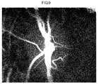
- FIG. 5 shows an example of measurement values obtained from people of the white race.
- FIGS. 4 and 5 correspond to "depiction of a conventional blood flow map" described in FIG. 2 .
- FIGS. 4 and 5 are compared, it is found that the numerical value is displayed to be considerably high. Under the assumption that the size of the eyeball does not differ greatly among the races, it is considered that the amount of blood circulating within the eyeball does not differ greatly among the races.
- FIG. 6 is an image showing a laser reflection intensity map which is obtained by superimposing speckle images from which the synthesized blood flow map of FIG. 4 is obtained (an example for the case where the subject is the yellow race).
- FIG. 7 is an image showing a laser reflection intensity map obtained from a subject of the white race.
- Information representing the shift of each blood flow map is obtained from the step S3 as tracking information, and tracking is performed on speckle images, on the basis of which the synthesized blood flow map is calculated, in order to average them, a laser reflection intensity map as shown in FIG. 6 is obtained.
- FIG. 6 shows an example in which the subject is the yellow race. From FIG.
- FIG. 7 shows an example in which the subject is the white race. From FIG. 7 , it is found that little difference is present between the reflection intensity at the optic papilla and that at the remaining portion. This shows that the layer of the pigment epithelium widely spreading at the boundary between the retina and the choroid is dark in color in the case of people of the colored races and is almost clear in the case of people of the white races, and that the reflectance (or absorptivity) of laser light differs among the human races.
- the incident intensity used for calculation of the laser reflectance can be obtained as a signal representing the intensity of laser light radiated from the laser light irradiation system.
- the laser reflection intensity is obtained as the signal intensity of light reflected from each location within the observation region and detected by the light receiving section. For example, as exemplified above, it can be obtained from the laser reflection intensity map.
- the power of laser light output from the present blood flow image diagnosing device is adjusted by setting a laser output value using measurement software (step S1). In the case of caucasoid people, the internal scattering is strong, and light returning from the eyeground to the light receiving section is too strong. Therefore, the laser output is decreased.
- the laser output is set to be rather strong.
- the laser output laser light intensity signal
- the laser output required to obtain the map of FIG. 7 is only 5.
- the laser reflectance can be determined from the overall output of laser light applied to the eyeball and the average value of the laser reflection intensity map within a region of interest.
- step S5 measurement regions are recognized.
- the eyeground blood flow is measured mainly in three regions of interest; i.e., the choroid, the retina blood vessel, and the optic papilla tissue.
- the tissue blood flow at the optic papilla, and the blood flow of the choroid which are considered to closely relate to angiostenosis, glaucoma, and macular degeneration caused derivatively by medical diseases such as arteriosclerotic and diabetes.
- these blood flows differ in the positional relation with the pigment epithelium, they differ in the degree of influence of the pigment concentration. Namely, since the retina blood vessel is located closer to the surface layer than the pigment epithelium layer, when the pigment concentration is high, the backward scattering light from a deeper region decreases, and the reflection intensity of the blood vessel portion also decreases.
- step S6 the measurement regions are classified. Since the pigment concentration and its influence change among the measurement regions, different correction coefficients must be prepared for the respective measurement regions.
- step S7 the laser reflectance of each of the classified regions is calculated.
- a blood flow value is obtained from a synthesized blood flow map having undergone tracking processing, and a laser reflectance is obtained from the laser reflection intensity map.
- the obtained values are stored.
- the averaged value of the laser reflectance can be considered to reflect the pigment concentration which affects that region. Measurement must be performed a large number of times in order to obtain and store the above-mentioned data. In actual measurement, the stored data are used for correction.
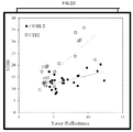
- step S8 a newly measured blood flow map is corrected. Namely, correction coefficients are applied to the blood flow map in accordance with the laser reflectances of the respective regions. For each region, the averaged laser reflection intensity and the averaged blood flow value are calculated. This calculation is repeated for all the stored data of healthy persons, whereby scatter diagrams are plotted, and regression lines are obtained.
- FIG. 10 shows scatter diagrams and regression lines obtained for two regions (choroid CHR and optic papilla tissue ONH-T). Each of the scatter diagrams represents the relation between the averaged blood flow value MBR and the laser reflection intensity. Although the inclination of the regression line changes among the regions, for increase and decrease of the laser reflectance in each region, it functions as a correction coefficient. In the example of FIG.
- data at the right end of the graph are those of the white race, data of the colored races are shown on the left side thereof such that the higher the pigment concentration, the closer to the left end.
- the relation between the averaged blood flow value MBR and the laser reflectance represented by such a regression line is stored in the image storage section.
- data of a certain colored race are newly obtained, data of, for example, the choroid is obtained, is converted to a value of the white race, and is compared with its standard value.
- the laser reflectance of that region is obtained, and is divided by the average laser reflectance of the white race located at the right end of FIG. 10 (the value stored in the storage section), and a resultant value is used as a correction coefficient.
- the averaged blood flow value MBR is divided by this correction coefficient, whereby a numerical value corrected for the influence of the pigment can be obtained and can be compared with that of the white race.
- step S9 the corrected blood flow map is depicted.
- the correction coefficients of the respective regions differ from one another.
- image comparison of the blood flow map becomes possible.
- FIG. 11 shows the result of correction performed on the blood flow map of the yellow race shown in FIG. 4 .
- FIG. 11 shows that the corrected numeral values are comparable to those of the blood flow map of the white race shown in FIG. 5 .
- a criteria e.g., a criteria that when the tissue blood flow of the optic papilla becomes equal to or lower than a predetermined cutoff value, the risk of glaucoma increases irrespective of the human race.
- the color of the palm of the hand is thin in color as compared with the back of the hand, and the differences among measured values are small as compared with those of the back of the hand. Accordingly, the correction coefficient for the palm of the hand differs from that for the back of the hand, and it is necessary to apply correction on a region-by-region basis as in the case of the eyeground.
- a possible method which realizes this is measuring the pigment concentration of a skin tissue of a subject (object under measurement) by using a skin color measurement device or the like and performing correction.
- this investigates the reflecting characteristic (or absorbing characteristic) for visible light, and does not show the characteristic for a laser wavelength used for measurement.
- the most feasible method is directly obtaining, from a laser scattering signal used for blood flow measurement, information of the characteristic of reflection (or the characteristic of absorption) by the pigment of the subject for the wavelength of the laser signal as in the case of the eyeground.
- the information of the pigment concentration is contained in the laser reflection intensity map shown in FIG. 6 or FIG. 7 .
- a value obtained by dividing the numerical value on this map by the incident intensity of laser light projected to the eyeground shows the ratio of reflection by the pigment (reflectance), which is inverse proportional to absorption.
- This allows application of first-stage correction.
- the influence of absorption by the pigment changes depending on the positional relation between a blood vessel or blood vessel layer to be detected and the pigment layer. Therefore, it become necessary to perform second-stage correction.
- the positional relations are classified into several groups, regions having the same positional relation are recognized as the same region, and a different correction coefficient corresponding to the region is applied.
- the first-stage correction for melanin concentration is performed using the above-described laser reflection intensity map.
- the second-stage correction is performed.
- the value corrected through the first-stage correction is multiplied by the correction coefficients of regions (e.g., the palm and back of the hand) which differ in terms of pigment concentration and the scattering characteristic of the corneal layer of epidermis.
- the time course change of speckles caused by the blood flow component of a blood vessel portion of people of the colored races is the same as that of people of the white race.
- backward scattering light becomes weak due to the pigment component contained in the background tissue, and the average light intensity (the numerator of the above-described expression) decreases as compared with caucasoid people.
- the blood flow value (MBR value) is displayed to be rather low.
- the pigment concentration is very high in regions other than the optic papilla. It is considered that no pigment epithelium exists at the optic papilla, and the backward scattering light is strong. Therefore, the blood flow value of the retina blood vessel is displayed to be sufficiently high at the optic papilla; however, when leaving the optic papilla, the blood flow decreases sharply, and it becomes almost impossible to recognize as a blood vessel.
- the influence of the pigment epithelium on the blood flow index MBR is strongest at the choroid, is second strongest at the retina blood vessel, and weakest at the optic papilla tissue.
Landscapes
- Health & Medical Sciences (AREA)
- Life Sciences & Earth Sciences (AREA)
- Engineering & Computer Science (AREA)
- Physics & Mathematics (AREA)
- General Health & Medical Sciences (AREA)
- Medical Informatics (AREA)
- Molecular Biology (AREA)
- Public Health (AREA)
- Biophysics (AREA)
- Biomedical Technology (AREA)
- Heart & Thoracic Surgery (AREA)
- Veterinary Medicine (AREA)
- Surgery (AREA)
- Animal Behavior & Ethology (AREA)
- Hematology (AREA)
- Ophthalmology & Optometry (AREA)
- Pathology (AREA)
- Physiology (AREA)
- Nuclear Medicine, Radiotherapy & Molecular Imaging (AREA)
- Radiology & Medical Imaging (AREA)
- Computer Vision & Pattern Recognition (AREA)
- Signal Processing (AREA)
- Cardiology (AREA)
- Vascular Medicine (AREA)
- General Physics & Mathematics (AREA)
- Theoretical Computer Science (AREA)
- Psychiatry (AREA)
- Artificial Intelligence (AREA)
- Quality & Reliability (AREA)
- Measuring Pulse, Heart Rate, Blood Pressure Or Blood Flow (AREA)
- Eye Examination Apparatus (AREA)
Applications Claiming Priority (2)
| Application Number | Priority Date | Filing Date | Title |
|---|---|---|---|
| JP2013090562A JP6062793B2 (ja) | 2013-04-23 | 2013-04-23 | 血流画像診断装置 |
| PCT/JP2014/060909 WO2014175154A1 (fr) | 2013-04-23 | 2014-04-17 | Dispositif de diagnostic par imagerie du flux sanguin et procédé de diagnostic |
Publications (2)
| Publication Number | Publication Date |
|---|---|
| EP2989977A1 true EP2989977A1 (fr) | 2016-03-02 |
| EP2989977A4 EP2989977A4 (fr) | 2016-06-01 |
Family
ID=51791733
Family Applications (1)
| Application Number | Title | Priority Date | Filing Date |
|---|---|---|---|
| EP14780741.6A Withdrawn EP2989977A4 (fr) | 2013-04-23 | 2014-04-17 | Dispositif de diagnostic par imagerie du flux sanguin et procédé de diagnostic |
Country Status (5)
| Country | Link |
|---|---|
| US (1) | US10098592B2 (fr) |
| EP (1) | EP2989977A4 (fr) |
| JP (1) | JP6062793B2 (fr) |
| CA (1) | CA2871400C (fr) |
| WO (1) | WO2014175154A1 (fr) |
Families Citing this family (19)
| Publication number | Priority date | Publication date | Assignee | Title |
|---|---|---|---|---|
| JP6062793B2 (ja) * | 2013-04-23 | 2017-01-18 | ソフトケア有限会社 | 血流画像診断装置 |
| US10178959B1 (en) * | 2014-07-10 | 2019-01-15 | Verily Life Sciences Llc | Non-invasive flow monitoring |
| KR102299361B1 (ko) * | 2014-09-03 | 2021-09-07 | 삼성전자주식회사 | 혈압을 모니터링하는 장치 및 방법, 혈압 모니터링 기능을 갖는 웨어러블 디바이스 |
| WO2016061052A1 (fr) | 2014-10-14 | 2016-04-21 | East Carolina University | Procédés, systèmes et produits-programmes informatique pour visualiser des structures anatomiques, un débit sanguin et une physiologie de perfusion à l'aide de techniques d'imagerie |
| EP3188652A4 (fr) * | 2014-10-14 | 2018-05-23 | East Carolina University | Procédés, systèmes et produits de programme informatique pour déterminer des paramètres d'état hémodynamique au moyen de signaux dérivés d'imagerie multispectrale de circulation et perfusion sanguine |
| US11553844B2 (en) * | 2014-10-14 | 2023-01-17 | East Carolina University | Methods, systems and computer program products for calculating MetaKG signals for regions having multiple sets of optical characteristics |
| CA3004408C (fr) | 2014-11-07 | 2023-09-19 | Ohio State Innovation Foundation | Procedes et appareil permettant d'effectuer une determination concernant un oeil dans des conditions d'eclairage ambiant |
| JP6507639B2 (ja) * | 2014-12-29 | 2019-05-08 | 花王株式会社 | 皮膚血流量の計測方法 |
| KR102411658B1 (ko) | 2015-01-15 | 2022-06-21 | 삼성전자주식회사 | 생체 정보 검출 장치 |
| KR102384225B1 (ko) | 2015-03-06 | 2022-04-07 | 삼성전자주식회사 | 혈압 측정 장치 및 방법 |
| IL239113A (en) | 2015-06-01 | 2016-12-29 | Elbit Systems Land & C4I Ltd | A system and method for determining audio characteristics from a body |
| KR101788850B1 (ko) * | 2015-08-24 | 2017-10-20 | 상명대학교산학협력단 | 영상 피부색 증폭을 통한 심박 신호 측정 방법 |
| KR102434701B1 (ko) | 2015-09-01 | 2022-08-22 | 삼성전자주식회사 | 생체 정보 획득 장치 및 생체 정보 획득 방법과 생체 정보 검사 장치 |
| EP3287070B1 (fr) | 2016-06-28 | 2019-01-23 | Softcare Co., Ltd. | Dispositif de diagnostic par imagerie dynamique de flux sanguin et procédé de diagnostic |
| KR102655671B1 (ko) | 2016-10-12 | 2024-04-05 | 삼성전자주식회사 | 생체정보 추정 장치 및 방법 |
| JP6489707B2 (ja) * | 2016-12-22 | 2019-03-27 | 義則 宮▲崎▼ | 緑内障のリスクレベルの判定補助方法、緑内障のリスクレベルを判定するための判定装置および判定プログラム |
| JP7266293B2 (ja) * | 2019-07-18 | 2023-04-28 | ソフトケア有限会社 | スペックル信号調整装置、並びにこれを使用した画像化測定装置の校正方法および画像化測定装置の異常診断方法 |
| US20210196119A1 (en) | 2019-12-27 | 2021-07-01 | Ohio State Innovation Foundation | Methods and apparatus for detecting a presence and severity of a cataract in ambient lighting |
| US11622682B2 (en) | 2019-12-27 | 2023-04-11 | Ohio State Innovation Foundation | Methods and apparatus for making a determination about an eye using color temperature adjusted ambient lighting |
Family Cites Families (20)
| Publication number | Priority date | Publication date | Assignee | Title |
|---|---|---|---|---|
| JPS63214238A (ja) | 1987-03-03 | 1988-09-06 | 藤居 良子 | 血流分布表示装置 |
| JPH01124437A (ja) | 1987-11-07 | 1989-05-17 | Hitoshi Fujii | 血流モニタ装置 |
| JP2813899B2 (ja) | 1989-09-26 | 1998-10-22 | 仁 藤居 | 眼科測定装置 |
| JP5161052B2 (ja) * | 2008-12-04 | 2013-03-13 | オリンパス株式会社 | 顕微鏡システム、標本観察方法およびプログラム |
| JPH08112262A (ja) | 1994-10-19 | 1996-05-07 | Hitoshi Fujii | 血流計 |
| US5725480A (en) * | 1996-03-06 | 1998-03-10 | Abbott Laboratories | Non-invasive calibration and categorization of individuals for subsequent non-invasive detection of biological compounds |
| WO2000006017A1 (fr) * | 1998-07-30 | 2000-02-10 | University Of Virginia Patent Foundation | Oxymetre permettant de former une image d'un vaisseau sanguin - |
| JP2003164431A (ja) | 2001-11-30 | 2003-06-10 | Hitoshi Fujii | 血流速度測定装置 |
| JP3855024B2 (ja) | 2001-12-13 | 2006-12-06 | 国立大学法人九州工業大学 | 血流速度測定装置 |
| JP2003310554A (ja) * | 2002-04-19 | 2003-11-05 | Topcon Corp | 眼科撮影装置 |
| WO2006124455A1 (fr) * | 2005-05-12 | 2006-11-23 | Cas Medical Systems, Inc. | Procede ameliore pour controler l'oxygenation du sang par spectrophotometrie |
| US7774036B2 (en) * | 2005-06-07 | 2010-08-10 | Oxymap Ehf | Automatic registration of images |
| US20100056936A1 (en) * | 2006-12-01 | 2010-03-04 | Hitoshi Fujii | Blood flow rate imaging device |
| US8100834B2 (en) * | 2007-02-27 | 2012-01-24 | J&M Shuler, Inc. | Method and system for monitoring oxygenation levels of a compartment for detecting conditions of a compartment syndrome |
| US7972266B2 (en) * | 2007-05-22 | 2011-07-05 | Eastman Kodak Company | Image data normalization for a monitoring system |
| US9028421B2 (en) | 2009-05-13 | 2015-05-12 | Kyushu Institute Of Technology | Blood flow image diagnosing device |
| EP2544583B1 (fr) * | 2010-03-08 | 2016-03-02 | Bruce Adams | Système, procédé et article pour la normalisation et l'amélioration d'images de tissus |
| US20120078114A1 (en) * | 2010-09-28 | 2012-03-29 | Point of Contact, LLC | System and method for real-time perfusion imaging |
| JP6066595B2 (ja) | 2011-07-29 | 2017-01-25 | キヤノン株式会社 | 眼底画像の画像処理装置、眼底画像の画像処理方法、及びプログラム |
| JP6062793B2 (ja) * | 2013-04-23 | 2017-01-18 | ソフトケア有限会社 | 血流画像診断装置 |
-
2013
- 2013-04-23 JP JP2013090562A patent/JP6062793B2/ja active Active
-
2014
- 2014-04-17 WO PCT/JP2014/060909 patent/WO2014175154A1/fr not_active Ceased
- 2014-04-17 CA CA2871400A patent/CA2871400C/fr active Active
- 2014-04-17 EP EP14780741.6A patent/EP2989977A4/fr not_active Withdrawn
- 2014-04-17 US US14/391,539 patent/US10098592B2/en active Active
Also Published As
| Publication number | Publication date |
|---|---|
| US20160278718A1 (en) | 2016-09-29 |
| EP2989977A4 (fr) | 2016-06-01 |
| WO2014175154A1 (fr) | 2014-10-30 |
| US10098592B2 (en) | 2018-10-16 |
| CA2871400C (fr) | 2019-06-18 |
| JP6062793B2 (ja) | 2017-01-18 |
| JP2014212851A (ja) | 2014-11-17 |
| CA2871400A1 (fr) | 2014-10-30 |
Similar Documents
| Publication | Publication Date | Title |
|---|---|---|
| US10098592B2 (en) | Blood flow image diagnosing device and method | |
| US20230064792A1 (en) | Illumination of an eye fundus using non-scanning coherent light | |
| US7926945B2 (en) | Device and method for monitoring, documenting and/or diagnosing the fundus | |
| US7404640B2 (en) | Monitoring blood flow in the retina using a line-scanning laser ophthalmoscope | |
| US9408532B2 (en) | Image processing apparatus and image processing method | |
| US20140198298A1 (en) | Image stitching method and camera system | |
| US20160106312A1 (en) | Data processing method and oct apparatus | |
| US7370967B2 (en) | Method and apparatus for optical imaging of retinal function | |
| WO2008117338A1 (fr) | Système de mesure de consommation d'oxygène et dispositif de diagnostic | |
| JP2017104381A (ja) | 情報取得装置、撮像装置及び情報取得方法 | |
| Carrasco-Zevallos et al. | Pupil tracking for real-time motion corrected anterior segment optical coherence tomography | |
| Cho et al. | Portable, non-invasive video imaging of retinal blood flow dynamics | |
| Rege et al. | Noninvasive assessment of retinal blood flow using a novel handheld laser speckle contrast imager | |
| US12150711B2 (en) | Blood flow analysis apparatus, blood flow analysis method, and recording medium | |
| JP6507639B2 (ja) | 皮膚血流量の計測方法 | |
| JP7096116B2 (ja) | 血流計測装置 | |
| Ganekal | Retinal functional imager (RFI): non-invasive functional imaging of the retina | |
| JP6771968B2 (ja) | 情報取得装置、撮影装置及び情報取得方法 | |
| CN111787843B (zh) | 血流测量装置 | |
| JP4255587B2 (ja) | 眼科装置 | |
| JP2017202267A (ja) | 情報取得装置、撮影装置及び情報取得方法 | |
| JP7221628B2 (ja) | 血流計測装置、情報処理装置、情報処理方法、及びプログラム | |
| Kinefuchi et al. | A study on dynamic retinal vessel evaluation using a compact near-infrared fundus imaging system | |
| JP2024138784A (ja) | 光画像形成装置、光画像形成装置の制御方法、及び、プログラム | |
| WO2025004840A1 (fr) | Dispositif de traitement d'informations, procédé de traitement d'informations et programme |
Legal Events
| Date | Code | Title | Description |
|---|---|---|---|
| PUAI | Public reference made under article 153(3) epc to a published international application that has entered the european phase |
Free format text: ORIGINAL CODE: 0009012 |
|
| 17P | Request for examination filed |
Effective date: 20151123 |
|
| AK | Designated contracting states |
Kind code of ref document: A1 Designated state(s): AL AT BE BG CH CY CZ DE DK EE ES FI FR GB GR HR HU IE IS IT LI LT LU LV MC MK MT NL NO PL PT RO RS SE SI SK SM TR |
|
| AX | Request for extension of the european patent |
Extension state: BA ME |
|
| A4 | Supplementary search report drawn up and despatched |
Effective date: 20160503 |
|
| RIC1 | Information provided on ipc code assigned before grant |
Ipc: A61B 3/12 20060101ALI20160427BHEP Ipc: A61B 5/026 20060101AFI20160427BHEP Ipc: A61B 3/10 20060101ALI20160427BHEP |
|
| DAX | Request for extension of the european patent (deleted) | ||
| RIC1 | Information provided on ipc code assigned before grant |
Ipc: G06T 5/00 20060101ALI20161222BHEP Ipc: A61B 3/10 20060101ALI20161222BHEP Ipc: G06T 7/00 20170101ALI20161222BHEP Ipc: A61B 5/00 20060101ALI20161222BHEP Ipc: A61B 3/00 20060101ALI20161222BHEP Ipc: A61B 3/12 20060101ALI20161222BHEP Ipc: A61B 5/026 20060101AFI20161222BHEP |
|
| GRAP | Despatch of communication of intention to grant a patent |
Free format text: ORIGINAL CODE: EPIDOSNIGR1 |
|
| STAA | Information on the status of an ep patent application or granted ep patent |
Free format text: STATUS: GRANT OF PATENT IS INTENDED |
|
| INTG | Intention to grant announced |
Effective date: 20170202 |
|
| STAA | Information on the status of an ep patent application or granted ep patent |
Free format text: STATUS: THE APPLICATION IS DEEMED TO BE WITHDRAWN |
|
| 18D | Application deemed to be withdrawn |
Effective date: 20170613 |