EP2990305B1 - Faux châssis de véhicule - Google Patents
Faux châssis de véhicule Download PDFInfo
- Publication number
- EP2990305B1 EP2990305B1 EP14788182.5A EP14788182A EP2990305B1 EP 2990305 B1 EP2990305 B1 EP 2990305B1 EP 14788182 A EP14788182 A EP 14788182A EP 2990305 B1 EP2990305 B1 EP 2990305B1
- Authority
- EP
- European Patent Office
- Prior art keywords
- partition wall
- subframe
- body portion
- central
- vehicle
- Prior art date
- Legal status (The legal status is an assumption and is not a legal conclusion. Google has not performed a legal analysis and makes no representation as to the accuracy of the status listed.)
- Not-in-force
Links
Images



Classifications
-
- B—PERFORMING OPERATIONS; TRANSPORTING
- B62—LAND VEHICLES FOR TRAVELLING OTHERWISE THAN ON RAILS
- B62D—MOTOR VEHICLES; TRAILERS
- B62D21/00—Understructures, i.e. chassis frame on which a vehicle body may be mounted
- B62D21/11—Understructures, i.e. chassis frame on which a vehicle body may be mounted with resilient means for suspension, e.g. of wheels or engine; sub-frames for mounting engine or suspensions
-
- B—PERFORMING OPERATIONS; TRANSPORTING
- B22—CASTING; POWDER METALLURGY
- B22C—FOUNDRY MOULDING
- B22C9/00—Moulds or cores; Moulding processes
- B22C9/10—Cores; Manufacture or installation of cores
-
- B—PERFORMING OPERATIONS; TRANSPORTING
- B22—CASTING; POWDER METALLURGY
- B22C—FOUNDRY MOULDING
- B22C9/00—Moulds or cores; Moulding processes
- B22C9/22—Moulds for peculiarly-shaped castings
- B22C9/24—Moulds for peculiarly-shaped castings for hollow articles
-
- B—PERFORMING OPERATIONS; TRANSPORTING
- B22—CASTING; POWDER METALLURGY
- B22D—CASTING OF METALS; CASTING OF OTHER SUBSTANCES BY THE SAME PROCESSES OR DEVICES
- B22D19/00—Casting in, on, or around objects which form part of the product
Definitions
- the present invention relates to a vehicular subframe disposed below a vehicular body for supporting a power plant used as a vehicular drive source, the subframe having left and right end portions supporting left and right suspensions, respectively.
- Some known vehicles have cast subframes disposed on vehicle frames, and torque rods connected to widthwise centers of the subframes.
- the widthwise center is hereinafter referred to as "connecting portion" of the subframe.
- the subframe supports a vehicular power plant.
- the power plant is, for example, an engine/transmission unit, that is, an integrated engine and transmission.
- the subframe has a hollow shape formed by a core placed in a cavity of a mold during casting.
- the subframe is light due to the hollow shape (see, e.g., JP-A-2012-091693 , on which the preamble of claim 1 is based).
- the connecting portion needs to be thick enough to obtain rigidity/strength, which makes it difficult to lighten the subframe.
- An object of the present invention is to provide a vehicular subframe which is light but has rigidity/strength at a connecting portion thereof.
- a vehicular subframe integrally formed by casting using a core comprising: a body portion having a top part and a bottom part, the body portion having a hollow space formed by the core to vertically space the top part and the bottom part from each other with a predetermined interval therebetween; left and right suspension support portions, the body portion having left and right end portions, the left and right suspension support portions being provided at the left and right end portions of the body portion, the suspension support portions being connected to suspension arms supporting suspensions; and a connecting portion provided at the body portion, the connecting portion being connected to a connecting member supporting a power plant used as a power source of a vehicle, wherein the body portion has a front part in a front-rear direction of the vehicle, and the connecting portion is provided at the front part of the body portion, and wherein the body portion includes a partition wall provided rearwardly of the connecting portion, the partition wall extending in the front-rear direction of the vehicle, the partition wall being connected
- the body portion includes a widthwise center located at a center of a width of the vehicle, and the partition wall is provided at the widthwise center of the body portion.
- the connecting portion is provided at the front part of the body portion.
- the partition wall is provided rearwardly of the connecting portion.
- the partition wall is connected to the top and bottom parts of the body portion.
- the partition wall which is provided rearwardly of the connecting portion, connects the top and bottom parts of the body portion to each other. This ensures rigidity/strength of the subframe, particularly, rigidity/strength of the rear region behind the connecting portion.
- the rear region bears a load applied through the connecting member to the connecting portion in the front-rear or vertical direction.
- the rigidity/strength of the rear region is obtained just by the partition wall connected to the top part and bottom part. For this reason, the subframe is lighter than if the subframe has an increased thickness, particularly if the entire periphery of the connection portion has an increased thickness.
- the partition wall is provided at the widthwise center of the body portion.
- the core used for forming the hollow part of the body portion has a bisected region corresponding to the widthwise center of the body portion.
- the partition wall is formed by molten material flowing between the core halves.
- a subframe 15 in the Embodiment is discussed hereinabelow.
- a vehicle body front structure 10 includes left and right side frames 11, 12 extending in a front-rear direction of the vehicle body, the subframe 15 attached to bottoms of the left and right side frames 11, 12, left and right suspension arms 16, 17 disposed on left and right end portions of the subframe 15, and left and right suspensions 21, 22 connected to the left and right suspension arms 16, 17.
- the vehicle body front structure 10 includes a steering gear box 24 attached to an upper part 15a of the subframe 15, and a torque rod (connecting member) 26 interconnecting the subframe 15 and a power plant 25.
- a steering wheel 29 is attached to a steering shaft 28 extending from the steering gear box 24.
- the power plant 25 is, e.g., an engine/transmission unit, that is, an integrated engine and transmission for use as a power source of the vehicle.
- the power plant is transversely disposed between the left and right side frames 11, 12.
- the subframe 15 is an integral casting of a thickness T1 formed from aluminum alloy by high pressure casting using a core unit 80 ( Fig. 9 ).
- the subframe 15 includes a body portion 32 having a hollow space formed using the core unit 80.
- the subframe 15 also includes a left vehicle body attachment portion 34 and a left suspension support portion 35 both of which are provided at a left end portion 32a of the body portion 32.
- the subframe 15 also includes a right vehicle body attachment portion 36 and a right suspension support portion 37 both of which are provided at a right end portion 32b of the body portion 32.
- the subframe 15 further includes a central connecting portion 38 provided at a front central portion of the body portion 32.
- the left vehicle body attachment portion 34 includes a left front attachment section 34a provided at a front part 32c of the left end portion 32a, and a left rear attachment section 34b provided at a rear part 32d of the left end portion 32a.
- the right vehicle body attachment portion 36 includes a right front attachment section 36a provided at a front part 32e of the right end portion 32b, and a right rear attachment section 36b provided at a rear part 32f of the right end portion 32b.
- the left front attachment section 34a and the left rear attachment section 34b are attached to the left side frame 11 ( Fig. 1 ) through bolts.
- the right front attachment section 36a and the right rear attachment section 36b are attached to the right side frame 12 ( Fig. 1 ) through bolts.
- the subframe 15 is attached to the left and right side frames 11, 12.
- the left suspension support portion 35 includes a left front connecting section 81 provided at the front part 32c of the left end portion 32a, and a left rear connecting section 82 provided at the rear part 32d of the left end portion 32a.
- the left front connecting section 81 which protrudes forward from the front part 32c, is located forwardly of the left front attachment section 34a.
- the left rear connecting section 82 which is located more inside than the left rear attachment section 34b ( Fig. 3 ) in a width direction of the vehicle, is interposed between the left rear attachment section 34b and the rear part 32d.
- the left suspension arm 16 has a front attachment portion 16a connected to the left front connecting section 81 through a left front support pin 84.
- the left suspension arm 16 has a rear attachment portion 16b connected to the left rear connecting section 82 through a left rear support pin.
- the left suspension 21 has a lower end portion 21a connected to the left suspension arm 16, and an upper end portion 21b connected to a left damper housing 13.
- the left damper housing 13 is formed integrally with the left side frame 11.
- the right suspension support portion 37 includes a right front connecting section 87 provided at the front part 32e of the right end portion 32b, and a right rear connecting section 88 provided at the rear part 32f of the right end portion 32b.
- the right front connecting section 87 which protrudes forward from the front part 32e, is located forwardly of the right front attachment section 36a.
- the right rear connecting section 88 which is located more inside than the right rear attachment section 36b ( Fig. 3 ) in the width direction of the vehicle, is interposed between the right rear attachment section 36b and the rear part 32f.
- the right suspension arm 17 has a front attachment portion 17a connected to the right front connecting section 87 through a right front support pin 91.
- the right suspension arm 17 has a rear attachment portion 17b connected to the right rear connecting section 88 through a right rear support pin.
- the right suspension arm 17 and the left suspension arm 16 are generally symmetrical to each other.
- the right suspension 22 has a lower end portion 22a connected to the right suspension arm 17, and an upper end portion 22b connected to a right damper housing 14.
- the right damper housing 14 is formed integrally with the right side frame 11.
- the body portion 32 has a widthwise center 32h located at the center of the vehicular width, and a front half 32g (front part in the front-rear direction of the vehicle).
- the central connecting portion 38 is provided at the widthwise center 32h and the front half 32g.
- the torque rod 26 has a proximal end portion 26a connected to the central connecting portion 38 by a bolt 51 ( Fig. 1 ) and a nut 52.
- the torque rod 26 has a distal end portion 26b connected to the power plant 25 by a bolt 53. This ensures that the power plant 25 is supported by the torque rod 26.
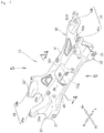
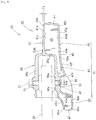
- the body portion 32 has an upwardly facing top part 41, a downwardly facing bottom part 42, a front wall 43 and a rear wall 44.
- the front wall 43 interconnects respective front end portions 41a, 42a of the top and bottom parts 41, 42.
- the rear wall 44 interconnects respective rear end portions 41b, 42b of the top and bottom parts 41, 42.
- the body portion 32 has a hollow part 45 defined by the top part 41, bottom part 41, front wall 43 and rear wall 44.
- the hollow part 45 is formed by the core unit 80 ( Fig. 9 ) during the casting of the subframe 15.
- the top part 41 and the bottom part 42 are vertically spaced from each other by a predetermined interval.
- the central connecting portion 38 is formed integrally with the front half 32g at a widthwise center of the top part 41.
- the bottom part 42 has a front portion 42c defining a bottom part 38a of the central connecting portion 38. Formed integrally with the front portion 42c is a connecting recessed portion 47 at a widthwise center of the bottom part 42.
- the central connecting portion 38 has an upper attachment hole 54 formed through a top part 38b thereof.
- the bottom part 38a of the central connecting portion 38 which includes the front portion 42c of the bottom part 42, has a lower attachment hole 55 formed therethrough.
- the bolt 51 which is inserted through the upper attachment hole 54 and the lower attachment hole 55, is connected to the torque rod 26.
- the body portion 32 includes a partition wall 61 provided at the widthwise center 32h.
- the partition wall 61 has a front partition wall portion 62 provided forwardly of the central connecting portion 38, a central partition wall portion 63 provided at the bottom part of the central connecting portion 38, and a rear partition wall portion (partition wall) 64 provided rearwardly of the central connecting portion 38.
- the partition wall 61 is discussed later in detail.
- the body portion 32 includes left and right, upper front lateral ribs 67, 68 and an upper rear central lateral rib 69. These ribs 67, 68, 69, which are disposed on an inner surface 41c ( Fig. 4 ) of the top part 41, reinforce the sub frame 15.
- the left upper front lateral rib 67 extends outwardly from a left end part 38c of the central connecting portion 38 in the width direction of the vehicle, and protrudes from the inner surface 41c toward the hollow part 45 ( Fig. 4 ).
- the right upper front lateral rib 68 is symmetrical to the left upper front lateral rib 67.
- the rib 68 extends outwardly from a right end part 38d of the central connecting portion 38 in the width direction of the vehicle, and protrudes from the inner surface 41c toward the hollow part 45.
- the upper rear central lateral rib 69 extends outwardly from a rear end part 64a of the rear partition wall portion 64 in opposite, i.e., left and right directions. In short, the rib 69 extends outwardly from the rear end part 64a in the width direction of the vehicle. The rib 69 protrudes from the inner surface 41c toward the hollow part 45 ( Fig. 4 ).
- the body portion 32 further a lower front central lateral rib 71 and left and right, rear inclining ribs 72, 73.
- the ribs 71, 72, 73 which are provided on an inner surface 42d ( Fig. 4 ) of the bottom part 42, reinforce the subframe 15.
- the lower front central lateral rib 71 extends outwardly from the front partition wall portion 62 in the opposite, i.e., left and right directions. In short, the rib 71 extends outwardly from the front partition wall portion 62 in the width direction of the vehicle. The rib 71 protrudes from the inner surface 42d toward the hollow part 45 ( Fig. 4 ).
- the left rear inclining rib 72 extends away from a left vicinity of the rear partition wall portion 64 in an outward and rearward direction of the vehicle.
- the rib 72 protrudes from the inner surface 42d toward the hollow part 45.
- the right rear inclining rib 73 is symmetric to the left rear inclining rib 72.
- the rib 73 extends away from a right vicinity of the rear partition wall portion 64 in the outward and rearward direction of the vehicle.
- the rib 73 protrudes from the inner surface 42d toward the hollow part 45.
- the partition wall 61 is discussed in detain below.
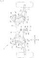
- the partition wall 61 is provided at the widthwise center 32h of the body portion 32 (see also Fig. 5 ).
- the partition wall 61 is defined by the front partition wall portion 62 provided forwardly of the central connecting portion 38, the central partition wall portion 63 provided at the bottom part of the central connecting portion 38, and the rear partition wall portion 64 provided rearwardly of the central connecting portion 38.
- the front partition wall portion 62 which is located at the widthwise center 32h of the body portion 32, is provided forwardly of and below the central connecting portion 38.
- This front partition wall portion 62 which extends in the front-rear direction of the vehicle, is connected to a front portion 41d of the top part 41, the front wall 43, a frontal portion 42e of the bottom part 42 and a front part 47a of the connecting recessed portion 47.
- the central partition wall portion 63 which is located at the widthwise center 32h of the body portion 32, is provided at the bottom part 38a of the central connecting portion 38. In short, the central partition wall portion 63 is disposed below the central connecting portion 38.
- This central partition wall portion 63 extends in the front-rear direction of the vehicle on an extended line of the front partition wall portion 62.
- the central partition wall portion 63 is connected to the bottom part 38a of the central connecting portion 38, a rear part 47b of the connecting recessed portion 47, and a central portion 42f of the bottom part 42.
- the rear partition wall portion 64 which is located at the widthwise center 32h of the body portion 32, is provided rearwardly of the central connecting portion 38.
- This rear partition wall portion 64 extends in the front-rear direction of the vehicle on an extended line of the central partition wall portion 63.
- the rear partition wall portion 64 is connected to a rear portion 41e of the top part 41, a rear part 38e of the central connecting portion 38, a rear portion 42g of the bottom part 42, and the rear wall 44.
- the rear partition wall portion 64 has a front end part 64b integral with a rear end part 63a of the central partition wall portion 63.
- the partition wall 61 i.e., the front partition wall portion 62, the central partition wall portion 63 and the rear partition wall portion 64.
- the subframe 15 is formed by casting with the core unit 80 ( Fig. 9 ) placed in a mold.
- the core unit 90 is defined by left and right, sand-made core members 81, 82 separated from each other.
- the core members 81, 82 correspond to the widthwise center 32h of the subframe 15 ( Fig. 3 ).
- the left core member 81 and the right core member 82 define an interval S1 therebetween.
- the interval S1 between the left core member 81 and the right core member 82 is filled with molten aluminum to form the partition wall 61 (the front partition wall portion 62, the central partition wall portion 63 and the rear partition wall portion 64 ( Fig. 4 )).
- the core unit 80 bisected into the left and right core units 81, 82 with the gap S1 therebetween, forms the partition wall 61 with ease. This means that the cost of the subframe 15 ( Fig. 3 ) is kept low with the partition wall 61 formed in this manner.
- a left upper front lateral groove 85 and a left half of an upper rear lateral groove 86 are provided at a top portion 84 of the left core member 81.
- the left upper front lateral groove 85 and the left half of the channel 86 form the left upper front lateral rib 67 and a left half of the upper rear central lateral rib 69, on a left half of the subframe 15 (top part 41) shown in Fig. 5 .
- a left half of a lower rear central lateral groove and a left rear inclining groove At a bottom portion of the left core member 81 are provided a left half of a lower rear central lateral groove and a left rear inclining groove.
- the left half of the lower rear central lateral groove and the left rear inclining groove form a left half of the lower front central lateral rib 71 and the left rear inclining rib 72, on the left half of the subframe 15 (bottom part 42) shown in Fig. 6 .
- the right core member 82 is generally symmetric to the left core member 81.
- a right upper front lateral groove 89 and a right half of an upper rear lateral groove 86 are formed on a top portion 88 of the right core member 82.
- the groove 89 and the right half of the groove 86 form the right upper front lateral rib 68 and a right half of the upper rear central lateral rib 69, on a right half of the subframe 15 (top part 41) shown in Fig. 5 .
- a right half of the lower rear central lateral groove and a right rear inclining groove are provided at a bottom portion of the right core member 82 .
- the right half of the lower rear central lateral groove and the right rear inclining groove form a right half of the lower front central lateral rib 71 and the right rear inclining rib 73, on a right half of the subframe 15 (bottom part 42) shown in Fig. 6 .
- the front partition wall portion 62 is provided below and forwardly of the central connecting portion 38, the central partition wall portion 63 provided below the central connecting portion 38, and the rear partition wall portion 64 disposed rearwardly of the central connecting portion 38. That is, the partition wall 61 is provided at the widthwise center 32h of the body portion 32.
- top part 41, bottom part 42, front wall 43 and rear wall 44 are connected to one another by the partition wall 61.
- the lower region 32i and/or the rear region 32j bears a vertical load F2 applied through the torque rod 26 to the central connecting portion 38.
- the lower region 32i and/or the rear region 32j bears a load other than the loads F1, F2 applied to the central connecting portion 38 through the torque rod 26.
- the subframe 15 well bears vibration transmitted thereto via the torque rod 26 from the power plant 25 ( Fig. 2 ).
- the rigidity/strength of the subframe 15 (more specifically, the lower region 32i, the rear region 32j) is obtained just by the partition wall 61 connecting the top part 41, bottom part 42, front wall 43 and rear wall 44 of the body portion 32 to one another.
- the subframe 15 is lighter than if the subframe 15 has a thickness T1 greater than that discussed above, particularly if the entire periphery of the connection portion has a thickness greater than that discussed above.
- vehicular subframe according to the present invention may be changed or improved where appropriate rather than being limited to the subframe discussed in the Embodiment.
- metal other than aluminum alloy may be used for the subframe although the subframe is made of aluminum alloy in the Embodiment.
- subframe 15 is formed by casting aluminum alloy under high pressure in the Embodiment, other methods may be used.
- central connecting portion 38 and the partition wall 61 may be provided at other regions than the body portion 32 although the central connecting portion 38 is provided at the front central portion of the body portion 32 and the partition wall 61 is provided at the widthwise center 32h of the body portion 32 in the Embodiment.
- subframe, the left and right suspension arms, the left and right suspensions, the power plant, the torque rod, the body portion, the left and right suspension support portions, the central connecting portion, the top part, the bottom part, the partition wall, and the rear partition wall portion are not limited to those discussed in the Embodiment, but may be changed to have other shapes or structures than those discussed in the Embodiment, where appropriate.
- the present invention is preferably applied to an automobile including a subframe disposed below the automotive body, the subframe having left and right end portions supporting left and right suspensions, respectively.
Landscapes
- Engineering & Computer Science (AREA)
- Mechanical Engineering (AREA)
- Chemical & Material Sciences (AREA)
- Combustion & Propulsion (AREA)
- Transportation (AREA)
- Body Structure For Vehicles (AREA)
Claims (2)
- Faux châssis de véhicule (15) formé, de manière solidaire, par moulage, le faux châssis (15) comprenant :une partie de corps (32) ayant une partie supérieure (41), une partie inférieure (42), des parties d'extrémité gauche et droite (32a, 32b) et une partie avant (32g) dans une direction avant - arrière du véhicule ;des parties de support de suspension gauche et droite (35, 37) prévues au niveau des parties d'extrémité gauche et droite (32a, 32b) de la partie de corps (32), les parties de support de suspension (35, 37) étant raccordées aux bras de suspension (16, 17) supportant des suspensions (21, 22) ; etune partie de raccordement (38) prévue au niveau de la partie avant (32g) de la partie de corps (32), la partie de raccordement (38) étant raccordée à un élément de raccordement (26) supportant une installation de puissance (25) utilisée en tant que source de puissance d'un véhicule ;caractérisé en ce que la partie de corps (32) a un espace creux (45) formé en utilisant un noyau (80) pour espacer verticalement la partie supérieure (41) et la partie inférieure (42) l'une de l'autre avec un intervalle prédéterminé entre elles ; etla partie de corps (32) comprend une paroi de séparation (64) prévue vers l'arrière de la partie de raccordement (38), la paroi de séparation (64) s'étendant dans la direction avant - arrière du véhicule, la paroi de séparation (64) étant raccordée à la partie supérieure (41) et à la partie inférieure (42) .
- Faux châssis de véhicule selon la revendication 1, dans lequel la partie de corps (32) comprend un centre dans le sens de la largeur (32h) positionné au niveau d'un centre d'une largeur du véhicule, et la paroi de séparation (64) est prévue au niveau du centre dans le sens de la largeur (32h) de la partie de corps (32).
Applications Claiming Priority (2)
| Application Number | Priority Date | Filing Date | Title |
|---|---|---|---|
| JP2013093972 | 2013-04-26 | ||
| PCT/JP2014/061719 WO2014175431A1 (fr) | 2013-04-26 | 2014-04-25 | Faux châssis de véhicule |
Publications (3)
| Publication Number | Publication Date |
|---|---|
| EP2990305A1 EP2990305A1 (fr) | 2016-03-02 |
| EP2990305A4 EP2990305A4 (fr) | 2017-02-15 |
| EP2990305B1 true EP2990305B1 (fr) | 2018-06-13 |
Family
ID=51791996
Family Applications (1)
| Application Number | Title | Priority Date | Filing Date |
|---|---|---|---|
| EP14788182.5A Not-in-force EP2990305B1 (fr) | 2013-04-26 | 2014-04-25 | Faux châssis de véhicule |
Country Status (7)
| Country | Link |
|---|---|
| US (1) | US9434417B2 (fr) |
| EP (1) | EP2990305B1 (fr) |
| JP (1) | JP6148333B2 (fr) |
| CN (1) | CN105246767B (fr) |
| BR (1) | BR112015026926A8 (fr) |
| MX (1) | MX365995B (fr) |
| WO (1) | WO2014175431A1 (fr) |
Families Citing this family (13)
| Publication number | Priority date | Publication date | Assignee | Title |
|---|---|---|---|---|
| JP6025972B2 (ja) * | 2013-04-26 | 2016-11-16 | 本田技研工業株式会社 | 車両のサブフレーム |
| DE102013108695B4 (de) * | 2013-08-12 | 2022-06-30 | Kirchhoff Automotive Deutschland Gmbh | Hilfsrahmen für eine Kraftfahrzeugachse |
| JP5953582B2 (ja) * | 2013-09-13 | 2016-07-20 | 本田技研工業株式会社 | 車両のサブフレーム |
| JP6137144B2 (ja) * | 2014-11-27 | 2017-05-31 | トヨタ自動車株式会社 | サスペンションメンバ |
| CN107971703A (zh) * | 2017-11-24 | 2018-05-01 | 芜湖禾田汽车工业有限公司 | 框架式结构铝合金焊接副车架的加工方法 |
| JP7056115B2 (ja) * | 2017-12-08 | 2022-04-19 | いすゞ自動車株式会社 | サスペンション装置 |
| JP7272928B2 (ja) * | 2019-10-18 | 2023-05-12 | トヨタ自動車株式会社 | 車両用支持部材 |
| JP2022152260A (ja) * | 2021-03-29 | 2022-10-12 | 本田技研工業株式会社 | サブフレーム |
| JP2022152262A (ja) * | 2021-03-29 | 2022-10-12 | 本田技研工業株式会社 | サブフレーム |
| JP2022152263A (ja) * | 2021-03-29 | 2022-10-12 | 本田技研工業株式会社 | サブフレーム |
| CN116443103A (zh) * | 2022-01-10 | 2023-07-18 | 本田技研工业株式会社 | 车辆框体结构 |
| JP7697395B2 (ja) * | 2022-04-05 | 2025-06-24 | トヨタ自動車株式会社 | サスペンションメンバ |
| KR102750312B1 (ko) | 2022-11-22 | 2025-01-08 | 서진산업 주식회사 | 랙하우징 일체형 서브프레임의 제조방법 |
Family Cites Families (20)
| Publication number | Priority date | Publication date | Assignee | Title |
|---|---|---|---|---|
| JP4138074B2 (ja) * | 1998-05-11 | 2008-08-20 | 本田技研工業株式会社 | 車両の車体構造 |
| JP2004051066A (ja) * | 2002-07-24 | 2004-02-19 | Kobe Steel Ltd | サブフレーム用アルミニウム合金中空形材およびサブフレーム |
| CN103085595B (zh) * | 2005-09-13 | 2016-02-10 | Ksm铸造集团有限公司 | 特别用于汽车的前桥支架 |
| JP4766517B2 (ja) * | 2006-03-20 | 2011-09-07 | ダイハツ工業株式会社 | 自動車の下部構造 |
| JP4901688B2 (ja) * | 2007-10-17 | 2012-03-21 | 本田技研工業株式会社 | 車体前部構造 |
| EP2222535B1 (fr) | 2007-11-08 | 2016-02-24 | KSM Castings Group GmbH | Support d'essieu avant pour véhicules automobiles |
| DE102009043474A1 (de) * | 2008-10-30 | 2010-05-12 | Ksm Castings Gmbh | Vorderachsträger für ein Kraftfahrzeug sowie Verfahren zu dessen Herstellung |
| KR101034019B1 (ko) * | 2008-11-20 | 2011-05-11 | 현대자동차주식회사 | 다이나믹 댐핑장치 |
| DE102010025555A1 (de) * | 2009-07-06 | 2011-01-13 | Ksm Castings Gmbh | Achsträger, insbesondere Vorderachsträger für Kraftfahrzeuge |
| CN201472467U (zh) * | 2009-09-17 | 2010-05-19 | 上海汽车集团股份有限公司 | 副车架及其中的加强支撑结构 |
| JP2012061921A (ja) | 2010-09-15 | 2012-03-29 | Suzuki Motor Corp | 車両のトルクロッド取付構造 |
| JP2012091693A (ja) * | 2010-10-27 | 2012-05-17 | Daihatsu Motor Co Ltd | サスペンションメンバ |
| DE102011115387A1 (de) * | 2010-11-02 | 2012-05-03 | Ksm Castings Gmbh | Achsträger, insbesondere Vorderachsträger für Kraftfahrzeuge |
| CN202071883U (zh) * | 2011-04-19 | 2011-12-14 | 宁波建新底盘系统有限公司 | 前副车架装配结构 |
| JP5910936B2 (ja) * | 2012-03-14 | 2016-04-27 | スズキ株式会社 | 車両の軽合金製サスペンションメンバ |
| US9216775B2 (en) * | 2012-07-27 | 2015-12-22 | Honda Motor Co., Ltd. | Subframe for vehicle |
| JP6025972B2 (ja) * | 2013-04-26 | 2016-11-16 | 本田技研工業株式会社 | 車両のサブフレーム |
| JP6021769B2 (ja) * | 2013-09-13 | 2016-11-09 | 本田技研工業株式会社 | 車両のサブフレーム及びその製造方法 |
| JP5953582B2 (ja) * | 2013-09-13 | 2016-07-20 | 本田技研工業株式会社 | 車両のサブフレーム |
| US9394002B2 (en) * | 2014-03-20 | 2016-07-19 | Ford Global Technologies, Llc | Extruded metal sub-frame for a vehicle |
-
2014
- 2014-04-25 WO PCT/JP2014/061719 patent/WO2014175431A1/fr not_active Ceased
- 2014-04-25 JP JP2015513854A patent/JP6148333B2/ja active Active
- 2014-04-25 CN CN201480030155.8A patent/CN105246767B/zh active Active
- 2014-04-25 EP EP14788182.5A patent/EP2990305B1/fr not_active Not-in-force
- 2014-04-25 BR BR112015026926A patent/BR112015026926A8/pt active Search and Examination
- 2014-04-25 US US14/786,426 patent/US9434417B2/en active Active
- 2014-04-25 MX MX2015014881A patent/MX365995B/es active IP Right Grant
Non-Patent Citations (1)
| Title |
|---|
| None * |
Also Published As
| Publication number | Publication date |
|---|---|
| BR112015026926A8 (pt) | 2019-12-31 |
| JP6148333B2 (ja) | 2017-06-14 |
| CN105246767B (zh) | 2017-08-08 |
| BR112015026926A2 (pt) | 2017-07-25 |
| CN105246767A (zh) | 2016-01-13 |
| US20160090125A1 (en) | 2016-03-31 |
| JPWO2014175431A1 (ja) | 2017-02-23 |
| WO2014175431A1 (fr) | 2014-10-30 |
| EP2990305A1 (fr) | 2016-03-02 |
| MX365995B (es) | 2019-06-20 |
| MX2015014881A (es) | 2016-06-21 |
| EP2990305A4 (fr) | 2017-02-15 |
| US9434417B2 (en) | 2016-09-06 |
Similar Documents
| Publication | Publication Date | Title |
|---|---|---|
| EP2990305A1 (fr) | Faux châssis de véhicule | |
| US9776660B2 (en) | Vehicle subframe | |
| US9150250B2 (en) | Sub-frame for vehicle | |
| US9399488B2 (en) | Vehicle subframe | |
| US9669873B2 (en) | Modular axle concept for a motor vehicle with electric drive | |
| TWI450834B (zh) | 前車體結構 | |
| US9108681B2 (en) | Sub-frame for vehicle | |
| JP5617144B2 (ja) | サスペンションメンバ | |
| JP2005280668A (ja) | 車両用サブフレーム | |
| CN105835955A (zh) | 工业车辆 | |
| US7883101B2 (en) | Body frame of motorcycle | |
| KR20080028103A (ko) | 복합 공법으로 제작된 차량용 알루미늄 서브프레임 | |
| CN205524470U (zh) | 用于车辆前部的车身布置结构 | |
| EP3514046A1 (fr) | Châssis de carrosserie pour véhicule à moteur à deux roues | |
| JP7022841B2 (ja) | サブフレーム構造 | |
| JP6164967B2 (ja) | 鞍乗り型車両の車体フレーム | |
| JP2011093410A (ja) | 鞍乗り型車両のスイングアーム構造 | |
| JP2011168087A (ja) | 自動車用のトルクロッド | |
| JP6279641B2 (ja) | 自動車のサブフレーム | |
| KR20160059045A (ko) | 차량용 스트럿바 | |
| JP2005297800A (ja) | 車両用サブフレーム | |
| JP6902242B2 (ja) | 自動車の前部車体構造 | |
| JP2025177936A (ja) | 車両前部構造 | |
| CN101723010A (zh) | 用于汽车的组合件系统和制造方法 | |
| JP2016141166A (ja) | サスペンションアーム取付構造 |
Legal Events
| Date | Code | Title | Description |
|---|---|---|---|
| PUAI | Public reference made under article 153(3) epc to a published international application that has entered the european phase |
Free format text: ORIGINAL CODE: 0009012 |
|
| 17P | Request for examination filed |
Effective date: 20151118 |
|
| AK | Designated contracting states |
Kind code of ref document: A1 Designated state(s): AL AT BE BG CH CY CZ DE DK EE ES FI FR GB GR HR HU IE IS IT LI LT LU LV MC MK MT NL NO PL PT RO RS SE SI SK SM TR |
|
| AX | Request for extension of the european patent |
Extension state: BA ME |
|
| DAX | Request for extension of the european patent (deleted) | ||
| A4 | Supplementary search report drawn up and despatched |
Effective date: 20170118 |
|
| RIC1 | Information provided on ipc code assigned before grant |
Ipc: B22C 9/24 20060101ALI20170112BHEP Ipc: B62D 21/00 20060101AFI20170112BHEP Ipc: B22C 9/10 20060101ALI20170112BHEP Ipc: B62D 21/11 20060101ALI20170112BHEP Ipc: B22C 9/22 20060101ALI20170112BHEP |
|
| GRAP | Despatch of communication of intention to grant a patent |
Free format text: ORIGINAL CODE: EPIDOSNIGR1 |
|
| STAA | Information on the status of an ep patent application or granted ep patent |
Free format text: STATUS: GRANT OF PATENT IS INTENDED |
|
| INTG | Intention to grant announced |
Effective date: 20171116 |
|
| GRAS | Grant fee paid |
Free format text: ORIGINAL CODE: EPIDOSNIGR3 |
|
| GRAA | (expected) grant |
Free format text: ORIGINAL CODE: 0009210 |
|
| STAA | Information on the status of an ep patent application or granted ep patent |
Free format text: STATUS: THE PATENT HAS BEEN GRANTED |
|
| AK | Designated contracting states |
Kind code of ref document: B1 Designated state(s): AL AT BE BG CH CY CZ DE DK EE ES FI FR GB GR HR HU IE IS IT LI LT LU LV MC MK MT NL NO PL PT RO RS SE SI SK SM TR |
|
| REG | Reference to a national code |
Ref country code: GB Ref legal event code: FG4D |
|
| REG | Reference to a national code |
Ref country code: CH Ref legal event code: EP Ref country code: AT Ref legal event code: REF Ref document number: 1008196 Country of ref document: AT Kind code of ref document: T Effective date: 20180615 |
|
| REG | Reference to a national code |
Ref country code: IE Ref legal event code: FG4D |
|
| REG | Reference to a national code |
Ref country code: DE Ref legal event code: R096 Ref document number: 602014027054 Country of ref document: DE |
|
| REG | Reference to a national code |
Ref country code: NL Ref legal event code: MP Effective date: 20180613 |
|
| REG | Reference to a national code |
Ref country code: LT Ref legal event code: MG4D |
|
| PG25 | Lapsed in a contracting state [announced via postgrant information from national office to epo] |
Ref country code: ES Free format text: LAPSE BECAUSE OF FAILURE TO SUBMIT A TRANSLATION OF THE DESCRIPTION OR TO PAY THE FEE WITHIN THE PRESCRIBED TIME-LIMIT Effective date: 20180613 Ref country code: SE Free format text: LAPSE BECAUSE OF FAILURE TO SUBMIT A TRANSLATION OF THE DESCRIPTION OR TO PAY THE FEE WITHIN THE PRESCRIBED TIME-LIMIT Effective date: 20180613 Ref country code: NO Free format text: LAPSE BECAUSE OF FAILURE TO SUBMIT A TRANSLATION OF THE DESCRIPTION OR TO PAY THE FEE WITHIN THE PRESCRIBED TIME-LIMIT Effective date: 20180913 Ref country code: CY Free format text: LAPSE BECAUSE OF FAILURE TO SUBMIT A TRANSLATION OF THE DESCRIPTION OR TO PAY THE FEE WITHIN THE PRESCRIBED TIME-LIMIT Effective date: 20180613 Ref country code: LT Free format text: LAPSE BECAUSE OF FAILURE TO SUBMIT A TRANSLATION OF THE DESCRIPTION OR TO PAY THE FEE WITHIN THE PRESCRIBED TIME-LIMIT Effective date: 20180613 Ref country code: FI Free format text: LAPSE BECAUSE OF FAILURE TO SUBMIT A TRANSLATION OF THE DESCRIPTION OR TO PAY THE FEE WITHIN THE PRESCRIBED TIME-LIMIT Effective date: 20180613 Ref country code: BG Free format text: LAPSE BECAUSE OF FAILURE TO SUBMIT A TRANSLATION OF THE DESCRIPTION OR TO PAY THE FEE WITHIN THE PRESCRIBED TIME-LIMIT Effective date: 20180913 |
|
| PG25 | Lapsed in a contracting state [announced via postgrant information from national office to epo] |
Ref country code: RS Free format text: LAPSE BECAUSE OF FAILURE TO SUBMIT A TRANSLATION OF THE DESCRIPTION OR TO PAY THE FEE WITHIN THE PRESCRIBED TIME-LIMIT Effective date: 20180613 Ref country code: LV Free format text: LAPSE BECAUSE OF FAILURE TO SUBMIT A TRANSLATION OF THE DESCRIPTION OR TO PAY THE FEE WITHIN THE PRESCRIBED TIME-LIMIT Effective date: 20180613 Ref country code: HR Free format text: LAPSE BECAUSE OF FAILURE TO SUBMIT A TRANSLATION OF THE DESCRIPTION OR TO PAY THE FEE WITHIN THE PRESCRIBED TIME-LIMIT Effective date: 20180613 Ref country code: GR Free format text: LAPSE BECAUSE OF FAILURE TO SUBMIT A TRANSLATION OF THE DESCRIPTION OR TO PAY THE FEE WITHIN THE PRESCRIBED TIME-LIMIT Effective date: 20180914 |
|
| REG | Reference to a national code |
Ref country code: AT Ref legal event code: MK05 Ref document number: 1008196 Country of ref document: AT Kind code of ref document: T Effective date: 20180613 |
|
| PG25 | Lapsed in a contracting state [announced via postgrant information from national office to epo] |
Ref country code: NL Free format text: LAPSE BECAUSE OF FAILURE TO SUBMIT A TRANSLATION OF THE DESCRIPTION OR TO PAY THE FEE WITHIN THE PRESCRIBED TIME-LIMIT Effective date: 20180613 |
|
| PG25 | Lapsed in a contracting state [announced via postgrant information from national office to epo] |
Ref country code: RO Free format text: LAPSE BECAUSE OF FAILURE TO SUBMIT A TRANSLATION OF THE DESCRIPTION OR TO PAY THE FEE WITHIN THE PRESCRIBED TIME-LIMIT Effective date: 20180613 Ref country code: CZ Free format text: LAPSE BECAUSE OF FAILURE TO SUBMIT A TRANSLATION OF THE DESCRIPTION OR TO PAY THE FEE WITHIN THE PRESCRIBED TIME-LIMIT Effective date: 20180613 Ref country code: SK Free format text: LAPSE BECAUSE OF FAILURE TO SUBMIT A TRANSLATION OF THE DESCRIPTION OR TO PAY THE FEE WITHIN THE PRESCRIBED TIME-LIMIT Effective date: 20180613 Ref country code: EE Free format text: LAPSE BECAUSE OF FAILURE TO SUBMIT A TRANSLATION OF THE DESCRIPTION OR TO PAY THE FEE WITHIN THE PRESCRIBED TIME-LIMIT Effective date: 20180613 Ref country code: IS Free format text: LAPSE BECAUSE OF FAILURE TO SUBMIT A TRANSLATION OF THE DESCRIPTION OR TO PAY THE FEE WITHIN THE PRESCRIBED TIME-LIMIT Effective date: 20181013 Ref country code: AT Free format text: LAPSE BECAUSE OF FAILURE TO SUBMIT A TRANSLATION OF THE DESCRIPTION OR TO PAY THE FEE WITHIN THE PRESCRIBED TIME-LIMIT Effective date: 20180613 Ref country code: PL Free format text: LAPSE BECAUSE OF FAILURE TO SUBMIT A TRANSLATION OF THE DESCRIPTION OR TO PAY THE FEE WITHIN THE PRESCRIBED TIME-LIMIT Effective date: 20180613 |
|
| PG25 | Lapsed in a contracting state [announced via postgrant information from national office to epo] |
Ref country code: IT Free format text: LAPSE BECAUSE OF FAILURE TO SUBMIT A TRANSLATION OF THE DESCRIPTION OR TO PAY THE FEE WITHIN THE PRESCRIBED TIME-LIMIT Effective date: 20180613 Ref country code: SM Free format text: LAPSE BECAUSE OF FAILURE TO SUBMIT A TRANSLATION OF THE DESCRIPTION OR TO PAY THE FEE WITHIN THE PRESCRIBED TIME-LIMIT Effective date: 20180613 |
|
| REG | Reference to a national code |
Ref country code: DE Ref legal event code: R097 Ref document number: 602014027054 Country of ref document: DE |
|
| PLBE | No opposition filed within time limit |
Free format text: ORIGINAL CODE: 0009261 |
|
| STAA | Information on the status of an ep patent application or granted ep patent |
Free format text: STATUS: NO OPPOSITION FILED WITHIN TIME LIMIT |
|
| 26N | No opposition filed |
Effective date: 20190314 |
|
| PG25 | Lapsed in a contracting state [announced via postgrant information from national office to epo] |
Ref country code: DK Free format text: LAPSE BECAUSE OF FAILURE TO SUBMIT A TRANSLATION OF THE DESCRIPTION OR TO PAY THE FEE WITHIN THE PRESCRIBED TIME-LIMIT Effective date: 20180613 Ref country code: SI Free format text: LAPSE BECAUSE OF FAILURE TO SUBMIT A TRANSLATION OF THE DESCRIPTION OR TO PAY THE FEE WITHIN THE PRESCRIBED TIME-LIMIT Effective date: 20180613 |
|
| PG25 | Lapsed in a contracting state [announced via postgrant information from national office to epo] |
Ref country code: AL Free format text: LAPSE BECAUSE OF FAILURE TO SUBMIT A TRANSLATION OF THE DESCRIPTION OR TO PAY THE FEE WITHIN THE PRESCRIBED TIME-LIMIT Effective date: 20180613 |
|
| REG | Reference to a national code |
Ref country code: CH Ref legal event code: PL |
|
| REG | Reference to a national code |
Ref country code: BE Ref legal event code: MM Effective date: 20190430 |
|
| GBPC | Gb: european patent ceased through non-payment of renewal fee |
Effective date: 20190425 |
|
| PG25 | Lapsed in a contracting state [announced via postgrant information from national office to epo] |
Ref country code: LU Free format text: LAPSE BECAUSE OF NON-PAYMENT OF DUE FEES Effective date: 20190425 Ref country code: MC Free format text: LAPSE BECAUSE OF FAILURE TO SUBMIT A TRANSLATION OF THE DESCRIPTION OR TO PAY THE FEE WITHIN THE PRESCRIBED TIME-LIMIT Effective date: 20180613 |
|
| PG25 | Lapsed in a contracting state [announced via postgrant information from national office to epo] |
Ref country code: CH Free format text: LAPSE BECAUSE OF NON-PAYMENT OF DUE FEES Effective date: 20190430 Ref country code: LI Free format text: LAPSE BECAUSE OF NON-PAYMENT OF DUE FEES Effective date: 20190430 Ref country code: GB Free format text: LAPSE BECAUSE OF NON-PAYMENT OF DUE FEES Effective date: 20190425 |
|
| PG25 | Lapsed in a contracting state [announced via postgrant information from national office to epo] |
Ref country code: BE Free format text: LAPSE BECAUSE OF NON-PAYMENT OF DUE FEES Effective date: 20190430 Ref country code: FR Free format text: LAPSE BECAUSE OF NON-PAYMENT OF DUE FEES Effective date: 20190430 |
|
| PG25 | Lapsed in a contracting state [announced via postgrant information from national office to epo] |
Ref country code: TR Free format text: LAPSE BECAUSE OF FAILURE TO SUBMIT A TRANSLATION OF THE DESCRIPTION OR TO PAY THE FEE WITHIN THE PRESCRIBED TIME-LIMIT Effective date: 20180613 |
|
| PG25 | Lapsed in a contracting state [announced via postgrant information from national office to epo] |
Ref country code: IE Free format text: LAPSE BECAUSE OF NON-PAYMENT OF DUE FEES Effective date: 20190425 |
|
| PG25 | Lapsed in a contracting state [announced via postgrant information from national office to epo] |
Ref country code: PT Free format text: LAPSE BECAUSE OF FAILURE TO SUBMIT A TRANSLATION OF THE DESCRIPTION OR TO PAY THE FEE WITHIN THE PRESCRIBED TIME-LIMIT Effective date: 20181015 |
|
| PG25 | Lapsed in a contracting state [announced via postgrant information from national office to epo] |
Ref country code: HU Free format text: LAPSE BECAUSE OF FAILURE TO SUBMIT A TRANSLATION OF THE DESCRIPTION OR TO PAY THE FEE WITHIN THE PRESCRIBED TIME-LIMIT; INVALID AB INITIO Effective date: 20140425 Ref country code: MT Free format text: LAPSE BECAUSE OF FAILURE TO SUBMIT A TRANSLATION OF THE DESCRIPTION OR TO PAY THE FEE WITHIN THE PRESCRIBED TIME-LIMIT Effective date: 20180613 |
|
| PGFP | Annual fee paid to national office [announced via postgrant information from national office to epo] |
Ref country code: DE Payment date: 20210330 Year of fee payment: 8 |
|
| PG25 | Lapsed in a contracting state [announced via postgrant information from national office to epo] |
Ref country code: MK Free format text: LAPSE BECAUSE OF FAILURE TO SUBMIT A TRANSLATION OF THE DESCRIPTION OR TO PAY THE FEE WITHIN THE PRESCRIBED TIME-LIMIT Effective date: 20180613 |
|
| REG | Reference to a national code |
Ref country code: DE Ref legal event code: R119 Ref document number: 602014027054 Country of ref document: DE |
|
| PG25 | Lapsed in a contracting state [announced via postgrant information from national office to epo] |
Ref country code: DE Free format text: LAPSE BECAUSE OF NON-PAYMENT OF DUE FEES Effective date: 20221103 |