WO2014175431A1 - Faux châssis de véhicule - Google Patents
Faux châssis de véhicule Download PDFInfo
- Publication number
- WO2014175431A1 WO2014175431A1 PCT/JP2014/061719 JP2014061719W WO2014175431A1 WO 2014175431 A1 WO2014175431 A1 WO 2014175431A1 JP 2014061719 W JP2014061719 W JP 2014061719W WO 2014175431 A1 WO2014175431 A1 WO 2014175431A1
- Authority
- WO
- WIPO (PCT)
- Prior art keywords
- vehicle
- main body
- partition wall
- subframe
- center
- Prior art date
- Legal status (The legal status is an assumption and is not a legal conclusion. Google has not performed a legal analysis and makes no representation as to the accuracy of the status listed.)
- Ceased
Links
Images





Classifications
-
- B—PERFORMING OPERATIONS; TRANSPORTING
- B62—LAND VEHICLES FOR TRAVELLING OTHERWISE THAN ON RAILS
- B62D—MOTOR VEHICLES; TRAILERS
- B62D21/00—Understructures, i.e. chassis frame on which a vehicle body may be mounted
- B62D21/11—Understructures, i.e. chassis frame on which a vehicle body may be mounted with resilient means for suspension, e.g. of wheels or engine; sub-frames for mounting engine or suspensions
-
- B—PERFORMING OPERATIONS; TRANSPORTING
- B22—CASTING; POWDER METALLURGY
- B22C—FOUNDRY MOULDING
- B22C9/00—Moulds or cores; Moulding processes
- B22C9/10—Cores; Manufacture or installation of cores
-
- B—PERFORMING OPERATIONS; TRANSPORTING
- B22—CASTING; POWDER METALLURGY
- B22C—FOUNDRY MOULDING
- B22C9/00—Moulds or cores; Moulding processes
- B22C9/22—Moulds for peculiarly-shaped castings
- B22C9/24—Moulds for peculiarly-shaped castings for hollow articles
-
- B—PERFORMING OPERATIONS; TRANSPORTING
- B22—CASTING; POWDER METALLURGY
- B22D—CASTING OF METALS; CASTING OF OTHER SUBSTANCES BY THE SAME PROCESSES OR DEVICES
- B22D19/00—Casting in, on, or around objects which form part of the product
Definitions
- the present invention relates to a vehicle subframe that is provided below a vehicle body, supports left and right suspensions at left and right ends, and supports a power plant serving as a drive source of the vehicle.
- a vehicle body frame is provided with a cast sub-frame, and a torque rod is connected to the center of the sub-frame in the vehicle width direction (hereinafter referred to as “connecting portion”).
- connecting portion By connecting the torque rod to the subframe, the power plant of the vehicle is supported by the subframe via the torque rod.
- the power plant is an engine / transmission unit in which an engine and a transmission are integrally formed.
- This sub-frame is formed in a hollow shape with a core disposed in a casting mold cavity during casting.
- a hollow shape By forming the subframe in a hollow shape, it is possible to reduce the weight of the subframe (see, for example, Patent Document 1).
- An object of the present invention is to provide a vehicle subframe that can ensure the rigidity and strength of the connecting portion and can reduce the weight of the subframe.
- the upper part and the lower part are provided in the vertical direction at a predetermined interval by being integrally cast using the core and formed hollow by the core.
- the vehicle subframe includes a partition wall connected to the upper portion and the lower portion and extending in the vehicle front-rear direction.
- the partition wall is provided in a vehicle width direction central portion of the main body portion.
- connection part was provided in the front part of the vehicle front-back direction among the main-body parts. Further, a partition wall was provided at the rear of the connecting portion, and the partition wall was connected to the upper part and the lower part.
- the rigidity and strength of the rear part can be secured simply by connecting the partition wall to the upper part and the lower part at the rear of the connecting part.
- a partition was provided in the vehicle width direction center part of the main-body part.
- the partition wall is formed by flowing molten metal between the divided cores. Can do.
- a partition can be easily formed between the divided cores only by dividing the core into two.
- FIG. 4 is a sectional view taken along line 4-4 of FIG.
- FIG. 5 is a view taken in the direction of arrow 5 in FIG. 3.
- FIG. 6 is a view taken along arrow 6 in FIG. 3.
- FIG. 7 is a sectional view taken along line 7-7 in FIG.
- FIG. 8 is a sectional view taken along line 8-8 in FIG.
- It is a top view which shows the core unit which concerns on this invention. It is a figure explaining the example which supports the load input into the center connection part of the sub-frame which concerns on this invention.
- the vehicle body front structure 10 includes left and right side frames 11, 12 arranged in the longitudinal direction of the vehicle body, and subs attached below the left and right side frames 11, 12.
- the frame 15 includes left and right suspension arms 16 and 17 provided at left and right ends of the subframe 15, and left and right suspensions 21 and 22 connected to the left and right suspension arms 16 and 17.
- the vehicle body front structure 10 further includes a steering gear box 24 attached to the upper portion 15a of the subframe 15 and a torque rod (connecting member) 26 that connects the subframe 15 and the power plant 25.
- a steering wheel 29 is attached to a steering shaft 28 extending from the steering gear box 24.
- the power plant 25 is an engine / transmission unit in which an engine and a transmission are integrally formed and serves as a drive source of the vehicle.
- the power plant 25 is disposed horizontally between the left and right side frames 11 and 12.
- the subframe 15 is formed into a wall thickness T ⁇ b> 1 by high pressure casting integrally with an aluminum alloy using a core unit 80 (see FIG. 9).
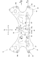
- the subframe 15 includes a main body portion 32 formed in a hollow shape by the core unit 80, a left vehicle body attachment portion 34 and a left suspension support portion 35 provided at the left end portion 32 a of the main body portion 32, and the main body portion 32.
- a right vehicle body attachment portion 36 and a right suspension support portion 37 provided at the right end portion 32 b and a central coupling portion 38 provided at the front center portion of the main body portion 32 are provided.
- the left vehicle body attachment portion 34 includes a left front attachment portion 34a provided at the front portion 32c of the left end portion 32a of the main body portion 32, and a left rear attachment portion 34b provided at the rear portion 32d of the left end portion 32a of the main body portion 32. including.
- the right vehicle body attachment portion 36 includes a right front attachment portion 36 a provided at the front portion 32 e of the right end portion 32 b of the main body portion 32 and a rear portion 32 f of the right end portion 32 b of the main body portion 32. And a right rear mounting portion 36b provided.
- the left front attachment portion 34a and the left rear attachment portion 34b are attached to the left side frame 11 (see FIG. 1) with bolts. Further, the right front attachment portion 36a and the right rear attachment portion 36b are attached to the right side frame 12 (see FIG. 1) with bolts. Thereby, the sub-frame 15 is attached to the left and right side frames 11 and 12.
- the left suspension support portion 35 is connected to the left front connecting portion 81 provided at the front portion 32 c of the left end portion 32 a of the main body portion 32 and the rear portion 32 d of the left end portion 32 a of the main body portion 32. And a left rear connecting portion 82 provided.
- the left front connecting portion 81 is disposed in front of the left front mounting portion 34a by being provided so as to protrude from the front portion 32c to the front of the vehicle.
- the left rear connecting portion 82 is interposed between the left rear mounting portion 34b and the rear portion 32d by being provided on the inner side in the vehicle width direction from the left rear mounting portion 34b (see also FIG. 3).
- a front mounting portion 16 a of the left suspension arm 16 is connected to the left front connection portion 81 via a left front support pin 84.
- the rear attachment portion 16b of the left suspension arm 16 is connected to the left rear connection portion 82 via a left rear support pin.
- a lower end 21 a of the left suspension 21 is connected to the left suspension arm 16, and an upper end 21 b of the left suspension 21 is connected to the left damper housing 13.
- the left damper housing 13 is formed integrally with the left side frame 11. Therefore, the left suspension 21 is supported by the left suspension arm 16. As a result, the left suspension 21 is supported by the left suspension support portion 35 via the left suspension arm 16.
- the right suspension support portion 37 is connected to the right front connection portion 87 provided at the front portion 32 e of the right end portion 32 b of the main body portion 32 and the rear portion 32 f of the right end portion 32 b of the main body portion 32. And a right rear connecting portion 88 provided.
- the right front connecting portion 87 is disposed in front of the vehicle from the right front mounting portion 36a by being provided so as to protrude from the front portion 32e to the front of the vehicle.
- the right rear connecting portion 88 is interposed between the right rear mounting portion 36b and the rear portion 32f by being provided on the inner side in the vehicle width direction from the right rear mounting portion 36b (see also FIG. 3).
- a front mounting portion 17 a of the right suspension arm 17 is connected to the right front connection portion 87 via a right front support pin 91.
- the rear attachment portion 17b of the right suspension arm 17 is connected to the right rear connection portion 88 via a right rear support pin.
- the right suspension arm 17 is a member that is substantially symmetrical with the left suspension arm 16.
- a lower end 22 a of the right suspension 22 is connected to the right suspension arm 17, and an upper end 22 b of the right suspension 22 is connected to the right damper housing 14.
- the right damper housing 14 is formed integrally with the right side frame 11. Therefore, the right suspension 22 is supported by the right suspension arm 17. As a result, the right suspension 22 is supported by the right suspension support portion 37 via the right suspension arm 17.
- a central coupling portion 38 is provided in the vehicle width direction center portion 32 h of the main body portion 32 and in the front half portion (front portion in the vehicle front-rear direction) 32 g.
- the base end portion 26 a of the torque rod 26 is connected to the central connecting portion 38 by a bolt 51 (see FIG. 1) and a nut 52.
- a tip end portion 26 b of the torque rod 26 is connected to the power plant 25 by a bolt 53. Thereby, the power plant 25 is supported by the torque rod 26.
- the main body 32 includes an upper part 41 facing upward, a lower part 42 facing downward, a front wall 43 connecting the front end parts 41a and 42a of the upper part 41 and the lower part 42, and an upper part. 41 and the rear wall 44 which connects each rear-end part 41b of the lower part 42, 42b.
- a hollow portion 45 is formed by an upper portion 41, a lower portion 42, a front wall 43 and a rear wall 44.
- the hollow portion 45 is formed by the core unit 80 (see FIG. 9) when the subframe 15 is cast.
- the upper part 41 and the lower part 42 are provided at a predetermined interval in the vertical direction.
- a central connecting portion 38 is integrally formed at the center of the upper portion 41 in the vehicle width direction and at the front half portion 32g.
- a connecting recess 47 is integrally formed in the center of the lower portion 42 in the vehicle width direction and in a front portion (that is, a portion corresponding to the lower portion 38a of the central connecting portion 38) 42c.
- An upper mounting hole 54 is formed in the upper part 38b of the central coupling part 38, and a lower mounting hole 55 is formed in the lower part 38a (including the front part 42c of the lower part 42) of the central coupling part 38.
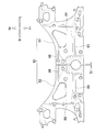
- the main body portion 32 includes a partition wall portion 61 provided in the vehicle width direction center portion 32 h.
- the partition wall portion 61 includes a front partition wall 62 provided in front of the center connection portion 38 in the vehicle, a center partition wall 63 provided in the lower portion of the center connection portion 38, and a rear partition wall provided in the rear of the center connection portion 38 ( Partition wall) 64.
- the partition wall 61 will be described in detail later.
- the main body 32 includes left and right upper front horizontal ribs 67 and 68 and an upper rear center horizontal rib 69 which are provided on the inner surface 41 c (see FIG. 4) of the upper portion 41 and reinforce the subframe 15.
- the upper left front horizontal rib 67 extends outward in the vehicle width direction from the left end portion 38c of the central connecting portion 38, and protrudes from the inner surface 41c toward the hollow portion 45 (see FIG. 4).
- the upper right front horizontal rib 68 is a rib symmetrical to the upper left front horizontal rib 67, extends outward in the vehicle width direction from the right end portion 38d of the central coupling portion 38, and protrudes from the inner surface 41c toward the hollow portion 45. ing.
- the upper rear center horizontal rib 69 extends outward in the vehicle width direction from the rear end portion 64a of the rear partition wall 64 in both the left and right directions, and protrudes from the inner surface 41c toward the hollow portion 45 (see FIG. 4). ing.
- the upper portion 41 ie, the subframe 15
- the ribs 67, 68, 69 is reinforced by the ribs 67, 68, 69. .
- the main body 32 includes a lower front center horizontal rib 71 and left and right rear inclined ribs 72 and 73 provided on the inner surface 42d (see FIG. 4) of the lower portion 42 to reinforce the subframe 15.
- the lower front center horizontal rib 71 extends outward in the vehicle width direction from the front partition wall 62 in both the left and right directions, and protrudes from the inner surface 42d toward the hollow portion 45 (see FIG. 4).
- the left rear inclined rib 72 extends from the vicinity of the left side of the rear partition wall 64 so as to spread outward in the vehicle width direction toward the rear of the vehicle, and protrudes toward the hollow portion 45 from the inner surface 42d.
- the right rear inclined rib 73 is symmetrical to the left rear inclined rib 72, extends from the right side of the rear partition wall 64 so as to spread outward in the vehicle width direction toward the rear of the vehicle, and is hollow from the inner surface 42d. It protrudes toward 45.
- the lower front center horizontal rib 71 and the left and right rear inclined ribs 72, 73 are provided on the inner surface 42d of the lower part 42, the lower part 42 (ie, the subframe 15) is reinforced by the ribs 71, 72, 73.
- a partition wall 61 is provided in the vehicle width direction central portion 32 h of the main body 32 (see also FIG. 5).
- the partition wall portion 61 includes a front partition wall 62 provided in front of the center connection portion 38 in the vehicle, a center partition wall 63 provided in the lower portion of the center connection portion 38, and a rear partition wall 64 provided in the rear of the center connection portion 38 in the vehicle. It consists of and.
- the front partition wall 62 is provided in the vehicle width direction center portion 32 h of the main body portion 32 in front of the center connection portion 38 and below the center connection portion 38.
- the front partition wall 62 is connected to the front portion 41d of the upper portion 41, the front wall 43, the front portion 42e of the lower portion 42, and the front portion 47a of the connecting recess 47, and extends in the vehicle front-rear direction.
- the central partition wall 63 is provided in the vehicle width direction central portion 32 h of the main body portion 32 at the lower portion 38 a of the central coupling portion 38 and below the central coupling portion 38. .
- the central partition wall 63 is connected to the lower portion 38 a of the central connection portion 38, the rear portion 47 b of the connection recess 47 and the central portion 42 f of the lower portion 42, and extends in the vehicle front-rear direction on the extension line of the front partition wall 62.
- the rear partition wall 64 is provided on the vehicle rear side of the central connecting portion 38 in the vehicle width direction central portion 32 h of the main body portion 32.
- the rear partition wall 64 is connected to the rear portion 41 e of the upper portion 41, the rear portion 38 e of the central connection portion 38, the rear portion 42 g of the lower portion 42, and the rear wall 44, and extends in the vehicle front-rear direction on the extension line of the central partition wall 63.
- the front end portion 64 b of the rear partition wall 64 is integrally connected to the rear end portion 63 a of the central partition wall 63. Therefore, the upper part 41, the lower part 42, the front wall 43 and the rear wall 44 of the main body part 32 are integrally connected by the partition wall part 61 (that is, the front partition wall 62, the central partition wall 63 and the rear partition wall 64).
- the subframe 15 is formed in a state where the core unit 80 (see FIG. 9) is disposed in the casting mold during casting. As shown in FIG. 9, the core unit 80 is divided into a left core 81 and a right core 82 in a state corresponding to the vehicle width direction central portion 32h of the subframe 15 (see FIG. 3). It is made of sand.
- the partition wall portion 61 can be easily formed in the subframe 15 with a simple configuration in which the core unit 80 is divided into the left core 81 and the right core 82 and the gap S1 is secured. . Thereby, the partition part 61 can be formed in the state which suppressed the cost of the sub-frame 15 (refer FIG. 3).
- the left core 81 is provided with a left half portion of an upper left front lateral groove 85 and an upper rear lateral groove 86 in an upper portion 84.
- the left half of the upper left front horizontal groove 85 and the upper rear horizontal groove 86 the left half of the upper left front horizontal rib 67 and the upper rear central horizontal rib 69 is formed in the left half of the subframe 15 (upper part 41) shown in FIG.
- the left core 81 is provided with a left half portion of the lower rear center lateral groove and a left rear inclined groove in the lower portion.
- the left half of the lower front center horizontal rib 71 and the left rear inclined rib 72 are formed in the left half of the subframe 15 (lower part 42) shown in FIG.
- the left core 81 is provided with a left half portion of an upper left front lateral groove 85 and an upper rear lateral groove 86 in an upper portion 84.
- the left half of the upper left front horizontal rib 67 and the upper rear central horizontal rib 69 is formed in the left half of the
- the right core 82 is a member substantially symmetrical to the left core 81, and the upper half 88 is provided with the right half of the upper right front lateral groove 89 and the upper rear lateral groove 86.
- the right half of the upper right front lateral groove 89 and the upper rear lateral groove 86 the right half of the upper right front lateral rib 68 and the upper rear center lateral rib 69 are formed in the right half of the subframe 15 (upper part 41) shown in FIG.
- the right core 82 is provided with a right half portion of the lower rear center lateral groove and a right rear inclined groove in the lower portion.
- the right half of the lower front center horizontal rib 71 and the right rear inclined rib 73 are formed in the right half of the subframe 15 (lower part 42) shown in FIG.
- a front partition 62 is provided below the center connecting portion 38 in front of the vehicle
- a center partition 63 is provided below the central connecting portion 38
- a rear partition 64 is provided behind the center connecting portion 38 in the vehicle. It has been. That is, the partition wall portion 61 is provided in the vehicle width direction center portion 32 h of the main body portion 32. Further, the upper portion 41, the lower portion 42, the front wall 43 and the rear wall 44 of the main body portion 32 are integrally connected by a partition wall portion 61.
- the rigidity and strength of the subframe 15 (particularly, the lower portion 32i of the central coupling portion 38 and the rear portion 32j behind the vehicle of the central coupling portion 38) can be ensured.
- the vehicle front-rear direction load F1 input to the central coupling portion 38 via the torque rod 26 can be supported by the lower portion 32i and the rear portion 32j.
- the vertical load F2 input to the central coupling portion 38 via the torque rod 26 can be supported by the lower portion 32i and the rear portion 32j.
- loads in other directions can be supported by the lower portion 32i and the rear portion 32j, not limited to the loads F1 and F2 that are input to the central coupling portion 38 via the torque rod 26.
- the loads F1 and F2 and loads in other directions can be supported by the lower part 32i and the rear part 32j.
- the vibration of the power plant 25 (see FIG. 2) is transmitted to the subframe 15 via the torque rod 26, the transmitted vibration can be suitably supported by the subframe 15.
- the rigidity and strength of the subframe 15 (particularly, the lower portion 32i and the rear portion 32j) can be increased by simply connecting the upper portion 41, the lower portion 42, the front wall 43 and the rear wall 44 of the main body portion 32 with the partition wall portion 61. It can be secured. Thereby, the weight reduction of the sub-frame 15 can be achieved compared with the case where the thickness dimension T1 of the sub-frame 15 (especially the thickness dimension of the whole circumference
- the sub-frame of the vehicle according to the present invention is not limited to the above-described embodiment, and can be changed or improved as appropriate.
- the subframe 15 made of aluminum alloy has been described.
- the present invention is not limited to this, and the present invention can be applied to other metals.
- the present invention is not limited to this, and the present invention can be applied to other castings.
- the central connecting portion (connecting portion) 38 is provided in the front center portion of the main body portion 32 and the partition wall portion 61 is provided in the vehicle width direction central portion 32h of the main body portion 32 has been described.
- the central coupling portion 38 and the partition wall portion 61 may be provided in other parts of the main body portion 32.
- subframe left and right suspension arms, left and right suspension, power plant, torque rod, main body, left and right suspension support, central connection, upper, lower, partition, rear partition, etc.
- the shape and configuration are not limited to those illustrated, and can be changed as appropriate.
- the present invention is suitable for application to an automobile provided with a subframe that is provided below the vehicle body and supports the left suspension at the left end and the right suspension at the right end.
- SYMBOLS 10 Vehicle body front part structure, 15 ... Sub-frame (vehicle sub-frame), 16, 17 ... Left and right suspension arm (suspension arm), 21, 22 ... Left and right suspension (suspension), 25 ... Power plant, 26 ... Torque rod (connecting member), 32 ... body part, 32a ... left end part of body part, 32b ... right end part of body part, 32g ... front half part (front part in vehicle longitudinal direction), 32h ... vehicle width direction center of body part 35, 37 ... left and right suspension support parts, 38 ... central connection part (connection part), 41 ... upper part, 42 ... lower part, 61 ... partition wall part, 64 ... rear partition wall (partition wall), 80 ... core unit (medium Child).
- connection part connection part
Landscapes
- Engineering & Computer Science (AREA)
- Mechanical Engineering (AREA)
- Chemical & Material Sciences (AREA)
- Combustion & Propulsion (AREA)
- Transportation (AREA)
- Body Structure For Vehicles (AREA)
Abstract
Priority Applications (6)
| Application Number | Priority Date | Filing Date | Title |
|---|---|---|---|
| CN201480030155.8A CN105246767B (zh) | 2013-04-26 | 2014-04-25 | 车辆的副车架 |
| MX2015014881A MX365995B (es) | 2013-04-26 | 2014-04-25 | Estructura auxiliar del vehiculo. |
| JP2015513854A JP6148333B2 (ja) | 2013-04-26 | 2014-04-25 | 車両のサブフレーム |
| BR112015026926A BR112015026926A8 (pt) | 2013-04-26 | 2014-04-25 | subestrutura veicular |
| EP14788182.5A EP2990305B1 (fr) | 2013-04-26 | 2014-04-25 | Faux châssis de véhicule |
| US14/786,426 US9434417B2 (en) | 2013-04-26 | 2014-04-25 | Vehicle subframe |
Applications Claiming Priority (2)
| Application Number | Priority Date | Filing Date | Title |
|---|---|---|---|
| JP2013093972 | 2013-04-26 | ||
| JP2013-093972 | 2013-04-26 |
Publications (1)
| Publication Number | Publication Date |
|---|---|
| WO2014175431A1 true WO2014175431A1 (fr) | 2014-10-30 |
Family
ID=51791996
Family Applications (1)
| Application Number | Title | Priority Date | Filing Date |
|---|---|---|---|
| PCT/JP2014/061719 Ceased WO2014175431A1 (fr) | 2013-04-26 | 2014-04-25 | Faux châssis de véhicule |
Country Status (7)
| Country | Link |
|---|---|
| US (1) | US9434417B2 (fr) |
| EP (1) | EP2990305B1 (fr) |
| JP (1) | JP6148333B2 (fr) |
| CN (1) | CN105246767B (fr) |
| BR (1) | BR112015026926A8 (fr) |
| MX (1) | MX365995B (fr) |
| WO (1) | WO2014175431A1 (fr) |
Cited By (4)
| Publication number | Priority date | Publication date | Assignee | Title |
|---|---|---|---|---|
| US20150075896A1 (en) * | 2013-09-13 | 2015-03-19 | Honda Motor Co., Ltd. | Sub-frame for vehicle |
| US20220306203A1 (en) * | 2021-03-29 | 2022-09-29 | Honda Motor Co., Ltd. | Subframe |
| US20220306201A1 (en) * | 2021-03-29 | 2022-09-29 | Honda Motor Co., Ltd. | Subframe |
| JP2023153497A (ja) * | 2022-04-05 | 2023-10-18 | トヨタ自動車株式会社 | サスペンションメンバ |
Families Citing this family (9)
| Publication number | Priority date | Publication date | Assignee | Title |
|---|---|---|---|---|
| JP6025972B2 (ja) * | 2013-04-26 | 2016-11-16 | 本田技研工業株式会社 | 車両のサブフレーム |
| DE102013108695B4 (de) * | 2013-08-12 | 2022-06-30 | Kirchhoff Automotive Deutschland Gmbh | Hilfsrahmen für eine Kraftfahrzeugachse |
| JP6137144B2 (ja) * | 2014-11-27 | 2017-05-31 | トヨタ自動車株式会社 | サスペンションメンバ |
| CN107971703A (zh) * | 2017-11-24 | 2018-05-01 | 芜湖禾田汽车工业有限公司 | 框架式结构铝合金焊接副车架的加工方法 |
| JP7056115B2 (ja) * | 2017-12-08 | 2022-04-19 | いすゞ自動車株式会社 | サスペンション装置 |
| JP7272928B2 (ja) * | 2019-10-18 | 2023-05-12 | トヨタ自動車株式会社 | 車両用支持部材 |
| JP2022152260A (ja) * | 2021-03-29 | 2022-10-12 | 本田技研工業株式会社 | サブフレーム |
| CN116443103A (zh) * | 2022-01-10 | 2023-07-18 | 本田技研工业株式会社 | 车辆框体结构 |
| KR102750312B1 (ko) | 2022-11-22 | 2025-01-08 | 서진산업 주식회사 | 랙하우징 일체형 서브프레임의 제조방법 |
Citations (4)
| Publication number | Priority date | Publication date | Assignee | Title |
|---|---|---|---|---|
| JP2007253642A (ja) * | 2006-03-20 | 2007-10-04 | Daihatsu Motor Co Ltd | 自動車の下部構造 |
| JP2012061921A (ja) * | 2010-09-15 | 2012-03-29 | Suzuki Motor Corp | 車両のトルクロッド取付構造 |
| JP2012091693A (ja) | 2010-10-27 | 2012-05-17 | Daihatsu Motor Co Ltd | サスペンションメンバ |
| US8302979B2 (en) * | 2007-11-08 | 2012-11-06 | Ksm Castings Gmbh | Front-axle bracket for motor vehicles |
Family Cites Families (16)
| Publication number | Priority date | Publication date | Assignee | Title |
|---|---|---|---|---|
| JP4138074B2 (ja) * | 1998-05-11 | 2008-08-20 | 本田技研工業株式会社 | 車両の車体構造 |
| JP2004051066A (ja) * | 2002-07-24 | 2004-02-19 | Kobe Steel Ltd | サブフレーム用アルミニウム合金中空形材およびサブフレーム |
| CN103085595B (zh) * | 2005-09-13 | 2016-02-10 | Ksm铸造集团有限公司 | 特别用于汽车的前桥支架 |
| JP4901688B2 (ja) * | 2007-10-17 | 2012-03-21 | 本田技研工業株式会社 | 車体前部構造 |
| DE102009043474A1 (de) * | 2008-10-30 | 2010-05-12 | Ksm Castings Gmbh | Vorderachsträger für ein Kraftfahrzeug sowie Verfahren zu dessen Herstellung |
| KR101034019B1 (ko) * | 2008-11-20 | 2011-05-11 | 현대자동차주식회사 | 다이나믹 댐핑장치 |
| DE102010025555A1 (de) * | 2009-07-06 | 2011-01-13 | Ksm Castings Gmbh | Achsträger, insbesondere Vorderachsträger für Kraftfahrzeuge |
| CN201472467U (zh) * | 2009-09-17 | 2010-05-19 | 上海汽车集团股份有限公司 | 副车架及其中的加强支撑结构 |
| DE102011115387A1 (de) * | 2010-11-02 | 2012-05-03 | Ksm Castings Gmbh | Achsträger, insbesondere Vorderachsträger für Kraftfahrzeuge |
| CN202071883U (zh) * | 2011-04-19 | 2011-12-14 | 宁波建新底盘系统有限公司 | 前副车架装配结构 |
| JP5910936B2 (ja) * | 2012-03-14 | 2016-04-27 | スズキ株式会社 | 車両の軽合金製サスペンションメンバ |
| US9216775B2 (en) * | 2012-07-27 | 2015-12-22 | Honda Motor Co., Ltd. | Subframe for vehicle |
| JP6025972B2 (ja) * | 2013-04-26 | 2016-11-16 | 本田技研工業株式会社 | 車両のサブフレーム |
| JP6021769B2 (ja) * | 2013-09-13 | 2016-11-09 | 本田技研工業株式会社 | 車両のサブフレーム及びその製造方法 |
| JP5953582B2 (ja) * | 2013-09-13 | 2016-07-20 | 本田技研工業株式会社 | 車両のサブフレーム |
| US9394002B2 (en) * | 2014-03-20 | 2016-07-19 | Ford Global Technologies, Llc | Extruded metal sub-frame for a vehicle |
-
2014
- 2014-04-25 WO PCT/JP2014/061719 patent/WO2014175431A1/fr not_active Ceased
- 2014-04-25 JP JP2015513854A patent/JP6148333B2/ja active Active
- 2014-04-25 CN CN201480030155.8A patent/CN105246767B/zh active Active
- 2014-04-25 EP EP14788182.5A patent/EP2990305B1/fr not_active Not-in-force
- 2014-04-25 BR BR112015026926A patent/BR112015026926A8/pt active Search and Examination
- 2014-04-25 US US14/786,426 patent/US9434417B2/en active Active
- 2014-04-25 MX MX2015014881A patent/MX365995B/es active IP Right Grant
Patent Citations (4)
| Publication number | Priority date | Publication date | Assignee | Title |
|---|---|---|---|---|
| JP2007253642A (ja) * | 2006-03-20 | 2007-10-04 | Daihatsu Motor Co Ltd | 自動車の下部構造 |
| US8302979B2 (en) * | 2007-11-08 | 2012-11-06 | Ksm Castings Gmbh | Front-axle bracket for motor vehicles |
| JP2012061921A (ja) * | 2010-09-15 | 2012-03-29 | Suzuki Motor Corp | 車両のトルクロッド取付構造 |
| JP2012091693A (ja) | 2010-10-27 | 2012-05-17 | Daihatsu Motor Co Ltd | サスペンションメンバ |
Cited By (7)
| Publication number | Priority date | Publication date | Assignee | Title |
|---|---|---|---|---|
| US20150075896A1 (en) * | 2013-09-13 | 2015-03-19 | Honda Motor Co., Ltd. | Sub-frame for vehicle |
| US9150250B2 (en) * | 2013-09-13 | 2015-10-06 | Honda Motor Co., Ltd. | Sub-frame for vehicle |
| US20220306203A1 (en) * | 2021-03-29 | 2022-09-29 | Honda Motor Co., Ltd. | Subframe |
| US20220306201A1 (en) * | 2021-03-29 | 2022-09-29 | Honda Motor Co., Ltd. | Subframe |
| US12043312B2 (en) * | 2021-03-29 | 2024-07-23 | Honda Motor Co., Ltd. | Subframe |
| JP2023153497A (ja) * | 2022-04-05 | 2023-10-18 | トヨタ自動車株式会社 | サスペンションメンバ |
| JP7697395B2 (ja) | 2022-04-05 | 2025-06-24 | トヨタ自動車株式会社 | サスペンションメンバ |
Also Published As
| Publication number | Publication date |
|---|---|
| BR112015026926A8 (pt) | 2019-12-31 |
| EP2990305B1 (fr) | 2018-06-13 |
| JP6148333B2 (ja) | 2017-06-14 |
| CN105246767B (zh) | 2017-08-08 |
| BR112015026926A2 (pt) | 2017-07-25 |
| CN105246767A (zh) | 2016-01-13 |
| US20160090125A1 (en) | 2016-03-31 |
| JPWO2014175431A1 (ja) | 2017-02-23 |
| EP2990305A1 (fr) | 2016-03-02 |
| MX365995B (es) | 2019-06-20 |
| MX2015014881A (es) | 2016-06-21 |
| EP2990305A4 (fr) | 2017-02-15 |
| US9434417B2 (en) | 2016-09-06 |
Similar Documents
| Publication | Publication Date | Title |
|---|---|---|
| JP6148333B2 (ja) | 車両のサブフレーム | |
| JP6025972B2 (ja) | 車両のサブフレーム | |
| JP5953582B2 (ja) | 車両のサブフレーム | |
| JP6021769B2 (ja) | 車両のサブフレーム及びその製造方法 | |
| US9457863B2 (en) | Motorcycle frame structure | |
| CN1771160B (zh) | 车体框架结构 | |
| JP4516497B2 (ja) | 自動二輪車の車体フレーム | |
| JP2012136195A (ja) | サスペンションメンバ | |
| US20190061820A1 (en) | Auxiliary frame for motor vehicles | |
| JP6204089B2 (ja) | 自動二輪車の車体フレーム | |
| JP4418280B2 (ja) | 車両用サブフレーム | |
| CN100455480C (zh) | 自动二轮车的车架 | |
| JP2007302147A (ja) | 車両のサブフレーム構造 | |
| JP4676257B2 (ja) | サブフレーム | |
| JP2010069965A (ja) | フロントサスペンションメンバ | |
| JP5157470B2 (ja) | 自動二輪車のリヤスイングアームおよびその製造方法 | |
| JP5911174B2 (ja) | 車両用サブフレーム | |
| JP2011168087A (ja) | 自動車用のトルクロッド | |
| JPWO2020065900A1 (ja) | サブフレーム構造 | |
| JP2015030330A (ja) | 鞍乗り型車両の車体フレーム | |
| JP5230551B2 (ja) | 車両用フロントサブフレーム構造 | |
| JP4486396B2 (ja) | 車両用サブフレーム | |
| JP2017065336A (ja) | スイングアーム | |
| JP2010000873A (ja) | 車両用動力源の支持構造 | |
| JP2008307970A (ja) | 車両用サスペンションアームの取付構造 |
Legal Events
| Date | Code | Title | Description |
|---|---|---|---|
| 121 | Ep: the epo has been informed by wipo that ep was designated in this application |
Ref document number: 14788182 Country of ref document: EP Kind code of ref document: A1 |
|
| WWE | Wipo information: entry into national phase |
Ref document number: 14786426 Country of ref document: US |
|
| WWE | Wipo information: entry into national phase |
Ref document number: MX/A/2015/014881 Country of ref document: MX |
|
| NENP | Non-entry into the national phase |
Ref country code: DE |
|
| WWE | Wipo information: entry into national phase |
Ref document number: IDP00201506954 Country of ref document: ID |
|
| WWE | Wipo information: entry into national phase |
Ref document number: 2014788182 Country of ref document: EP |
|
| REG | Reference to national code |
Ref country code: BR Ref legal event code: B01A Ref document number: 112015026926 Country of ref document: BR |
|
| ENP | Entry into the national phase |
Ref document number: 2015513854 Country of ref document: JP Kind code of ref document: A |
|
| ENP | Entry into the national phase |
Ref document number: 112015026926 Country of ref document: BR Kind code of ref document: A2 Effective date: 20151023 |