EP2990601A1 - Verfahren zur verbesserung der leistung einer gasturbine - Google Patents
Verfahren zur verbesserung der leistung einer gasturbine Download PDFInfo
- Publication number
- EP2990601A1 EP2990601A1 EP15181483.7A EP15181483A EP2990601A1 EP 2990601 A1 EP2990601 A1 EP 2990601A1 EP 15181483 A EP15181483 A EP 15181483A EP 2990601 A1 EP2990601 A1 EP 2990601A1
- Authority
- EP
- European Patent Office
- Prior art keywords
- rotor
- sweep
- tip
- stall margin
- applying
- Prior art date
- Legal status (The legal status is an assumption and is not a legal conclusion. Google has not performed a legal analysis and makes no representation as to the accuracy of the status listed.)
- Granted
Links
Images



Classifications
-
- B—PERFORMING OPERATIONS; TRANSPORTING
- B23—MACHINE TOOLS; METAL-WORKING NOT OTHERWISE PROVIDED FOR
- B23P—METAL-WORKING NOT OTHERWISE PROVIDED FOR; COMBINED OPERATIONS; UNIVERSAL MACHINE TOOLS
- B23P15/00—Making specific metal objects by operations not covered by a single other subclass or a group in this subclass
- B23P15/04—Making specific metal objects by operations not covered by a single other subclass or a group in this subclass turbine or like blades from several pieces
-
- F—MECHANICAL ENGINEERING; LIGHTING; HEATING; WEAPONS; BLASTING
- F01—MACHINES OR ENGINES IN GENERAL; ENGINE PLANTS IN GENERAL; STEAM ENGINES
- F01D—NON-POSITIVE DISPLACEMENT MACHINES OR ENGINES, e.g. STEAM TURBINES
- F01D5/00—Blades; Blade-carrying members; Heating, heat-insulating, cooling or antivibration means on the blades or the members
- F01D5/12—Blades
- F01D5/14—Form or construction
- F01D5/141—Shape, i.e. outer, aerodynamic form
- F01D5/145—Means for influencing boundary layers or secondary circulations
-
- F—MECHANICAL ENGINEERING; LIGHTING; HEATING; WEAPONS; BLASTING
- F01—MACHINES OR ENGINES IN GENERAL; ENGINE PLANTS IN GENERAL; STEAM ENGINES
- F01D—NON-POSITIVE DISPLACEMENT MACHINES OR ENGINES, e.g. STEAM TURBINES
- F01D5/00—Blades; Blade-carrying members; Heating, heat-insulating, cooling or antivibration means on the blades or the members
- F01D5/12—Blades
- F01D5/14—Form or construction
- F01D5/141—Shape, i.e. outer, aerodynamic form
-
- F—MECHANICAL ENGINEERING; LIGHTING; HEATING; WEAPONS; BLASTING
- F01—MACHINES OR ENGINES IN GENERAL; ENGINE PLANTS IN GENERAL; STEAM ENGINES
- F01D—NON-POSITIVE DISPLACEMENT MACHINES OR ENGINES, e.g. STEAM TURBINES
- F01D5/00—Blades; Blade-carrying members; Heating, heat-insulating, cooling or antivibration means on the blades or the members
- F01D5/12—Blades
- F01D5/28—Selecting particular materials; Particular measures relating thereto; Measures against erosion or corrosion
- F01D5/288—Protective coatings for blades
-
- F—MECHANICAL ENGINEERING; LIGHTING; HEATING; WEAPONS; BLASTING
- F04—POSITIVE - DISPLACEMENT MACHINES FOR LIQUIDS; PUMPS FOR LIQUIDS OR ELASTIC FLUIDS
- F04D—NON-POSITIVE-DISPLACEMENT PUMPS
- F04D29/00—Details, component parts, or accessories
- F04D29/08—Sealings
- F04D29/16—Sealings between pressure and suction sides
- F04D29/161—Sealings between pressure and suction sides especially adapted for elastic fluid pumps
- F04D29/164—Sealings between pressure and suction sides especially adapted for elastic fluid pumps of an axial flow wheel
-
- F—MECHANICAL ENGINEERING; LIGHTING; HEATING; WEAPONS; BLASTING
- F04—POSITIVE - DISPLACEMENT MACHINES FOR LIQUIDS; PUMPS FOR LIQUIDS OR ELASTIC FLUIDS
- F04D—NON-POSITIVE-DISPLACEMENT PUMPS
- F04D29/00—Details, component parts, or accessories
- F04D29/26—Rotors specially for elastic fluids
- F04D29/32—Rotors specially for elastic fluids for axial flow pumps
- F04D29/321—Rotors specially for elastic fluids for axial flow pumps for axial flow compressors
- F04D29/324—Blades
-
- F—MECHANICAL ENGINEERING; LIGHTING; HEATING; WEAPONS; BLASTING
- F04—POSITIVE - DISPLACEMENT MACHINES FOR LIQUIDS; PUMPS FOR LIQUIDS OR ELASTIC FLUIDS
- F04D—NON-POSITIVE-DISPLACEMENT PUMPS
- F04D29/00—Details, component parts, or accessories
- F04D29/40—Casings; Connections of working fluid
- F04D29/52—Casings; Connections of working fluid for axial pumps
- F04D29/522—Casings; Connections of working fluid for axial pumps especially adapted for elastic fluid pumps
- F04D29/526—Details of the casing section radially opposing blade tips
-
- F—MECHANICAL ENGINEERING; LIGHTING; HEATING; WEAPONS; BLASTING
- F04—POSITIVE - DISPLACEMENT MACHINES FOR LIQUIDS; PUMPS FOR LIQUIDS OR ELASTIC FLUIDS
- F04D—NON-POSITIVE-DISPLACEMENT PUMPS
- F04D29/00—Details, component parts, or accessories
- F04D29/66—Combating cavitation, whirls, noise, vibration or the like; Balancing
- F04D29/68—Combating cavitation, whirls, noise, vibration or the like; Balancing by influencing boundary layers
- F04D29/681—Combating cavitation, whirls, noise, vibration or the like; Balancing by influencing boundary layers especially adapted for elastic fluid pumps
- F04D29/685—Inducing localised fluid recirculation in the stator-rotor interface
-
- F—MECHANICAL ENGINEERING; LIGHTING; HEATING; WEAPONS; BLASTING
- F05—INDEXING SCHEMES RELATING TO ENGINES OR PUMPS IN VARIOUS SUBCLASSES OF CLASSES F01-F04
- F05D—INDEXING SCHEME FOR ASPECTS RELATING TO NON-POSITIVE-DISPLACEMENT MACHINES OR ENGINES, GAS-TURBINES OR JET-PROPULSION PLANTS
- F05D2220/00—Application
- F05D2220/30—Application in turbines
- F05D2220/36—Application in turbines specially adapted for the fan of turbofan engines
-
- F—MECHANICAL ENGINEERING; LIGHTING; HEATING; WEAPONS; BLASTING
- F05—INDEXING SCHEMES RELATING TO ENGINES OR PUMPS IN VARIOUS SUBCLASSES OF CLASSES F01-F04
- F05D—INDEXING SCHEME FOR ASPECTS RELATING TO NON-POSITIVE-DISPLACEMENT MACHINES OR ENGINES, GAS-TURBINES OR JET-PROPULSION PLANTS
- F05D2240/00—Components
- F05D2240/20—Rotors
- F05D2240/30—Characteristics of rotor blades, i.e. of any element transforming dynamic fluid energy to or from rotational energy and being attached to a rotor
- F05D2240/307—Characteristics of rotor blades, i.e. of any element transforming dynamic fluid energy to or from rotational energy and being attached to a rotor related to the tip of a rotor blade
-
- F—MECHANICAL ENGINEERING; LIGHTING; HEATING; WEAPONS; BLASTING
- F05—INDEXING SCHEMES RELATING TO ENGINES OR PUMPS IN VARIOUS SUBCLASSES OF CLASSES F01-F04
- F05D—INDEXING SCHEME FOR ASPECTS RELATING TO NON-POSITIVE-DISPLACEMENT MACHINES OR ENGINES, GAS-TURBINES OR JET-PROPULSION PLANTS
- F05D2250/00—Geometry
- F05D2250/20—Three-dimensional
- F05D2250/29—Three-dimensional machined; miscellaneous
- F05D2250/294—Three-dimensional machined; miscellaneous grooved
-
- F—MECHANICAL ENGINEERING; LIGHTING; HEATING; WEAPONS; BLASTING
- F05—INDEXING SCHEMES RELATING TO ENGINES OR PUMPS IN VARIOUS SUBCLASSES OF CLASSES F01-F04
- F05D—INDEXING SCHEME FOR ASPECTS RELATING TO NON-POSITIVE-DISPLACEMENT MACHINES OR ENGINES, GAS-TURBINES OR JET-PROPULSION PLANTS
- F05D2250/00—Geometry
- F05D2250/30—Arrangement of components
- F05D2250/38—Arrangement of components angled, e.g. sweep angle
-
- Y—GENERAL TAGGING OF NEW TECHNOLOGICAL DEVELOPMENTS; GENERAL TAGGING OF CROSS-SECTIONAL TECHNOLOGIES SPANNING OVER SEVERAL SECTIONS OF THE IPC; TECHNICAL SUBJECTS COVERED BY FORMER USPC CROSS-REFERENCE ART COLLECTIONS [XRACs] AND DIGESTS
- Y02—TECHNOLOGIES OR APPLICATIONS FOR MITIGATION OR ADAPTATION AGAINST CLIMATE CHANGE
- Y02T—CLIMATE CHANGE MITIGATION TECHNOLOGIES RELATED TO TRANSPORTATION
- Y02T50/00—Aeronautics or air transport
- Y02T50/60—Efficient propulsion technologies, e.g. for aircraft
Definitions
- the present invention generally relates to gas turbine engines, and more particularly relates to rotors with stall margin and efficiency optimization and methods for improving gas turbine engine performance therewith.
- Gas turbine engines may be used to power various types of vehicles and systems.
- a gas turbine engine may include, for example, five major sections: a fan section, a compressor section, a combustor section, a turbine section, and an exhaust section.
- the fan section includes a fan that induces air from the surrounding environment into the engine and passes a fraction of this air toward the compressor section.
- the compressor section raises the pressure of the air it receives from the fan section and directs the compressed air into the combustor section where it is mixed with fuel and ignited.
- the high-energy combustion mixture then flows into and through the turbine section, thereby causing rotationally mounted turbine blades to rotate and generate energy.
- the combustion mixture exiting the turbine section is exhausted from the engine through the exhaust section.
- the remaining fraction of air induced into the fan section is transitioned through a bypass plenum and exhausted through a mixer nozzle.
- the fan includes at least one rotor.
- the compressor section is implemented with a combination of one or more axial compressors, mixed flow and/or centrifugal stages.
- An intermediate-pressure (IP) compressor also known as a "booster” may be included in some engines between the fan and a high-pressure (HP) compressor, to supercharge or boost the HP compressor helping to raise the overall pressure ratio of the engine cycle to higher levels.
- IP intermediate-pressure
- HP high-pressure
- Both the IP and HP compressors have one or more stages comprised of a rotor and a stator. Each of the fan and compressor rotors has a plurality of rotor blades.
- the plurality of rotor blades are spaced in a circumferential direction around a rotor hub 2 located coaxially around a longitudinal centerline axis.
- Each rotor blade 1 has a pressure sidewall 3 and a circumferentially opposing suction sidewall 4 extending in a radial direction between a root 6 and a tip 7 and in an axial direction between the leading edge 9 and a trailing edge 11.
- Stall margin is defined as the difference between operation of the compressor and the conditions that would be required to cause stall to occur.
- Mechanisms have been devised to extend the stable operating range of the fan and compressor (i.e., extend the range to stall). For example, rotor casing treatments are added after design of the rotor has been completed to increase the stall margin, but usually are associated with an efficiency penalty. The rotor casing treatments are conventionally added after rotor design if the stall margin is too low.
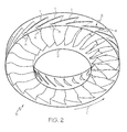
- Conventional "forward tip swept rotor blades" (a single forward tip swept rotor blade 1 is depicted in FIG. 1 ) of a conventional rotor 5 ( FIG.
- the "forward tip swept rotor blade” 1 includes an aft sweep extending over most of the rotor blade leading edge 9 with a local zone of forward sweep (encircled region A of FIGS. 1 and 2 ) near the tip 7 (from about 75% to 100% of the blade span).
- blade span refers to the geometry of the airfoil 1 or rotor blade that is defined in part by a span dimension S extending radially from the root 6 to the tip 7.
- Aerodynamic "sweep” is a conventional parameter represented by a sweep angle which is a function of the direction of the incoming air and the orientation of the airfoil surface in the axial, radial, and circumferential or tangential directions.
- the rotor direction of rotation is identified by arrow C in FIGS. 1 and 2 .
- a forward sweep is denoted by a negative value for the sweep angle.
- a neutral sweep has zero sweep angle.
- An aft (or rearward) sweep is denoted by a positive value for the sweep angle.
- Unfortunately the transition from the aft sweep along the blade span to the forward sweep (encircled region A) near the tip in conventional forward tip swept rotor blades creates a local transition zone (encircled region B of FIG. 1 ) of reduced efficiency and reduced range to stall.
- the forward sweep near the tip is also a mechanical design challenge with an associated risk of forced response and flutter.
- the gas turbine engine comprises a component having a rotor mounted in a rotor casing and having a plurality of rotor blades.
- a tip sweep is applied to a leading edge of one or more rotor blades each having a pressure sidewall and a circumferentially opposing suction sidewall extending in a radial direction between a root and a tip and in an axial direction between the leading edge and a trailing edge.
- One or more blade geometric design parameters are adjusted.
- a rotor casing treatment is applied to the rotor casing over at least one of the one or more rotor blades. The applying and adjusting steps are performed during design of the rotor and cause a measured stall margin to substantially match a required stall margin with an increase in efficiency of the component to a desired level.
- the method comprises determining a required stall margin for the rotor.
- a target efficiency level for the component is determined.
- a tip sweep is applied to one or more rotor blades of the plurality of rotor blades.
- One or more blade geometric design parameters are optionally adjusted.
- a rotor casing treatment is applied to the rotor casing above at least one of the one or more rotor blades with the tip sweep.
- a stall margin of the rotor is measured to obtain a measured stall margin. The measured stall margin is compared with the required stall margin.
- Efficiency of the component is measured.
- the steps of applying the tip sweep, adjusting the one or more blade geometric design parameters, and applying the rotor casing treatment are performed during design of the rotor to cause the measured stall margin to substantially match the required stall margin with a corresponding increase in efficiency of the component.
- the method comprises designing a rotor having a plurality of rotor blades spaced in a circumferential direction around a rotor hub located coaxially around a longitudinal centerline axis. Each rotor blade has pressure and suction sides extending between leading and trailing edges and longitudinally between a root and a tip.
- the designing step comprises adjusting one or more blade geometric design parameters and applying a rotor casing treatment to the rotor casing.
- the rotor casing has an inner surface surrounding the tip of the one or more rotor blades and spaced radially outwardly therefrom.
- the steps of adjusting the one or more blade geometric design parameters and applying the rotor casing treatment are performed to cause a measured stall margin to substantially match the required stall margin.
- the rotor is thereafter manufactured per the design for use in the component of the gas turbine engine.
- Various embodiments are directed to rotors with stall margin and efficiency optimization and methods for improving gas turbine engine performance therewith.
- the rotors according to exemplary embodiments of the present invention may be used in components of gas turbine engines that operate at high cycle pressure ratios and otherwise.
- the efficiency of the component e.g., a fan or compressor
- gas turbine engine specific fuel consumption and turbine operating temperatures are decreased in both steady state and transient operations relative to gas turbine engines that include conventional rotors.
- the fan rotor according to exemplary embodiments of the present invention may be used in a single-stage fan or in a multi-stage fan (not shown).
- the compressor rotor may be used in intermediate pressure (IP) compressors or "boosters" (sometimes known as low pressure (LP) compressors) and high pressure (HP) compressors, as well as in mixed flow compressors, centrifugal compressors, ducted fans, and propulsors.
- IP intermediate pressure
- HP high pressure
- rotor refers to a fan rotor, a compressor rotor, a mixed flow rotor, a centrifugal impeller, a ducted fan rotor, or a propulsor rotor.
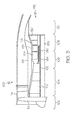
- FIG. 3 is a cross-sectional view of an exemplary gas turbine engine 100 including a fan section 102, a compressor section 104, a combustion section 106, a turbine section 108, and an exhaust section 110.
- the fan section 102 includes a fan 112 mounted in a fan casing 114. As noted previously, the fan 112 induces air from the surrounding environment into the engine and passes a fraction of this air toward the compressor section 104.
- the compressor section 104 includes at least one compressor and, in the depicted embodiment, includes an intermediate pressure compressor 120 (also known as a "booster" or LP compressor as noted above) and a high pressure compressor 122.
- the intermediate pressure compressor 120 raises the pressure of the air directed into it from the fan 112 and directs the compressed air into the high pressure compressor 122.
- the IP compressor and the HP compressor may be axi-symmetrical about a longitudinal centerline axis 123.
- the IP and HP compressors are mounted in a compressor casing 118.
- the combustion section 106 of gas turbine engine 100 includes a combustor 124 in which the high pressure air from the HP compressor is mixed with fuel and combusted to generate a combustion mixture of air and fuel. The combustion mixture is then directed into the turbine section 108.
- the turbine section 108 includes a number of turbines disposed in axial flow series.
- FIG. 3 depicts a high pressure turbine 126, an intermediate pressure turbine 128, and a low pressure turbine 130. While three turbines are depicted, it is to be understood that any number of turbines may be included according to design specifics.
- a propulsion gas turbine engine may comprise only a high pressure turbine and a low pressure turbine.
- the combustion mixture from the combustion section 106 expands through each turbine 126, 128, 130, causing them to rotate.
- each turbines 126, 128, 130 rotate, each respectively drives equipment in the gas turbine engine 100 via concentrically disposed shafts or spools 134, 136, 138.
- the combustion mixture is then exhausted through the exhaust section 110.
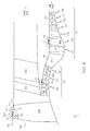
- FIG. 4 is a meridional sectional view through a portion of the fan 112, the IP compressor 120, and the HP compressor 122 of the exemplary gas turbine engine of FIG. 3 .
- the fan 112 includes one or more fan rotors 140 (such as the rotor depicted in FIG. 6 and/or the rotor depicted in FIG. 7 ) mounted in the fan casing 114.
- the fan 112 may be a single-stage fan or a multi-stage fan having fan stages.
- the IP and HP compressors include one or more compressor rotors 142 (such as the rotor depicted in FIG. 6 and/or the rotor depicted in FIG. 7 ) mounted in the compressor casing 118.
- the IP and HP compressors 120 and 122 depicted in FIG. 4 each include an inlet guide vane stage (V1) having a plurality of inlet guide vanes (a single variable inlet guide vane 121 (IGV) in each of the IP compressor and the HP compressor is depicted for ease of illustration in FIG. 4 ) and one or more compressor stages spaced in a circumferential direction around the longitudinal centerline axis 123.
- Each compressor stage has a compressor rotor 142 (e.g., R1, R2, and R3 in FIG. 4 ).
- Cooperating with each compressor rotor 142 is a corresponding stator vane 143 (e.g., S1, S2, and S3 in FIG. 4 ). While FIG.
- FIG. 4 depicts a fan 112 with a single fan stage, an IP compressor 120 with two compressor stages and an HP compressor 122 with three compressor stages each stage including a rotor and corresponding stator vane, it is to be understood that the number of fan stages and compressor stages may vary from that depicted, with a greater number of fan stages, and fewer or greater compressor stages.
- At least one of the fan rotor(s) 140 or compressor rotor(s) 142 include a plurality of rotor blades 144 rotationally mounted on a rotor hub 2 ( FIG. 6 ) mounted on a shaft (not shown).
- the rotor hub 2 is located coaxially around the longitudinal centerline axis 123.
- the plurality of rotor blades 144 extend in a radial direction and are generally spaced apart from one another around the circumference of the rotor hub 2.
- Each rotor blade includes a generally concave, pressure sidewall 3 and a circumferentially opposite, generally convex suction sidewall 4.
- the two sidewalls extend radially between a root 6 and an outer tip 7 and axially between a leading edge 9 and a trailing edge 11.
- the plurality of rotor blades is typically solid and has a generally conical tip 7, although other configurations may be provided.
- one or more of the plurality of rotor blades 144 in the rotor 140/142 comprise leading edge reduced forward tip swept rotor blades 144a ( FIG. 6 ).
- the reduced forward tip sweep is in encircled region K of FIG. 6 .
- FIG. 6 In another embodiment as depicted in FIG.
- one or more of the plurality of rotor blades comprise leading edge aft tip swept rotor blades 144b.
- the aft sweep is in encircled region L of FIG. 7 .
- Other blade geometric design parameters include solidity (ratio of chord/spacing), camber distribution, tip speed, incidence distribution, thickness distribution, chord distribution, hub to tip radius ratio (r-hub / r-tip), inlet specific flow, flowpath convergence, blade lean, etc.
- the generally circumferentially arcuate compressor casing 118 surrounds the stator vanes 143 and rotor blades 144 of the compressor 120/122 to at least partially define the compressor flow path ("core flow") with the rotor hub 2.
- the fan casing 114 FIGS. 3 and 4
- the compressor casing 118 have an inner surface 119 surrounding the rotor blade tip 7 and spaced radially outwardly therefrom.
- the inner surface 119 of the fan casing 114 and compressor casing 118 that is in closest proximity to the rotor blade tip 7 is referred to herein as a "rotor casing".
- the rotor rotates, and the rotor blades 144 draw mainstream air through the fan 112 and a fraction of the mainstream air into the IP and HP compressors 120/122.
- the mainstream air flows axially downstream between the rotor blades and the stator vanes, it is pressurized and directed through the rotor and stator stages, as desired, for further compression.
- the rotor blades 144a and 144b (and stator vanes) define airfoils having corresponding aerodynamic profiles or contours for pressurizing the mainstream air flow successively in axial stages. In operation, pressure of the air is increased as the air decelerates and diffuses through the stator and rotor airfoils.
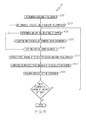
- a method 10 for improving gas turbine engine performance begins by determining a required stall margin for the component (e.g., fan, compressor, propulsor) (step 200).
- the required stall margin is determined by engine modeling techniques well known in the art.
- the required stall margin comprises a stall margin that defines a safe operating range in which system aerodynamic stability free of surge is determined.
- the required stall margin can be determined analytically, by testing, or both.
- Each fan and/or compressor stage can be analyzed or tested to determine its available stall margin that contributes to the required stall margin of the component.
- the method 10 for improving gas turbine engine performance continues by determining a target efficiency level for the component (step 300).
- the target efficiency level comprises a number of engine performance factors such as specific fuel consumption and turbine operating temperatures in both steady state and transient operations.
- Component efficiency can be determined analytically, by testing, or both.
- the method 10 for improving gas turbine engine performance continues by determining an optimum tip sweep angle for the leading edge of one or more rotor blades of the plurality of rotor blades 144 in the rotor under design that causes an increase in efficiency of the component, an increase in stall margin, or both (step 400).
- the optimum near tip sweep angle(s) may be determined analytically, by testing, or both.
- a tip sweep at the optimum near tip sweep angle may be applied (again, analytically, by testing, or both) near the tip of the leading edge of one or more rotor blades in the rotor under design.
- the tip sweep may be a negative tip sweep, a neutral tip sweep, or a positive tip sweep, as hereinafter described.
- the negative tip sweep results in a leading edge forward tip swept rotor blade (such as in the conventional leading edge forward tip swept rotor blade of FIGS. 1 and 2 or the leading edge reduced forward tip swept rotor blade of FIG. 6 ).
- the forward sweep of the leading edge reduced forward tip swept rotor blade of FIG. 6 is reduced relative to the forward sweep of the conventional leading edge forward tip swept rotor blade of FIGS. 1 and 2 .
- the neutral tip sweep results in a leading edge neutral tip swept rotor blade.
- the positive tip sweep results in an aft tip swept rotor blade.
- aerodynamic sweep is a conventional parameter represented by a local sweep angle which is a function of the direction of the incoming air and the orientation of the airfoil surface in the axial, radial, and circumferential or tangential directions.
- a forward sweep is denoted by a negative value for the sweep angle.
- An aft (or rearward) sweep is denoted by a positive value for the sweep angle.
- the leading edge reduced forward sweep may be reduced at the tip only relative to conventional forward swept rotor blades or the leading edge reduced forward sweep may be reduced starting from any span location along the blade leading edge up to the tip.
- FIG. 9 compares exemplary sweep angles for conventional forward swept rotor blades, leading edge reduced forward tip swept rotor blades 144a (such as depicted in FIG. 6 ) with a reduced forward sweep from 60% span to the blade tip, and leading edge aft tip swept rotor blades 144b (such as depicted in FIG. 7 ).
- Line D represents exemplary sweep angles for the conventional forward tip swept rotor blade 1 ( FIG. 1 ).
- Line E represents exemplary sweep angles for the leading edge reduced forward tip swept rotor blade 144a ( FIG. 6 ) and
- Line F represents exemplary sweep angles for the leading edge aft tip swept rotor blade 144b ( FIG. 7 ) according to exemplary embodiments of the present invention.
- the exemplary leading edge aft tip swept rotor blade 144b has an aft sweep (a positive sweep angle) from about 30% span all the way to the tip.
- the aft positive sweep angle(s) is/are as large as practicable.
- the leading edge 9 remains aft swept relative to the mainstream air over the entire high Mach number outboard sections of the airfoil ("core flow" in FIG. 4 ).
- Use of leading edge reduced forward tip swept rotor blades or leading edge aft tip swept rotor blades increases component efficiency but reduces the stall margin, causing a loss in engine stability.
- the increase in efficiency from reduced forward or aft sweep can reduce stall margin to levels below engine requirements.
- the optimization of both efficiency and stall margin is necessary to achieve the required stall margin at the highest possible efficiency.
- the required stall margin can be achieved with optimized fan and compressor efficiency, and reduced mechanical design complexity and flutter risk.
- steps 400, 500, and 600 are hereinafter described as being performed substantially simultaneously to cause a measured stall margin to substantially match a required stall margin with an increase in efficiency of the component, it is to be understood that the applying a tip sweep step (step 400) or the adjusting one or more blade geometric parameters step (step 500) may be optional, if the two other optimization steps cause the measured stall margin to substantially match the required stall margin with the increase in efficiency to a desired level.
- structural and aeroelastic concerns also have to be addressed as known to one skilled in the art.
- the trailing edge shape is modified to maintain aerodynamic characteristics in the blade passage and for mechanical considerations.
- the method 10 for improving gas turbine engine performance continues by adjusting one or more blade geometric design parameters such as solidity (ratio of chord/spacing), camber distribution, tip speed, incidence distribution, thickness distribution, chord distribution, hub to tip radius ratio (r-hub / r-tip), inlet specific flow, flowpath convergence, blade lean, etc. (step 500).
- blade geometric design parameters such as solidity (ratio of chord/spacing), camber distribution, tip speed, incidence distribution, thickness distribution, chord distribution, hub to tip radius ratio (r-hub / r-tip), inlet specific flow, flowpath convergence, blade lean, etc.
- Such blade geometric design parameters may be adjusted by methods well known in the art.
- the one or more blade geometric design parameters can be adjusted analytically, by testing, or both.
- the step of adjusting one or more blade geometric design parameters may be optional if the steps of applying the tip sweep and the rotor casing treatment (steps 400 and 600) cause the measured stall margin to substantially match the required stall margin with the increase in efficiency to the desired level.
- the method 10 for improving gas turbine engine performance continues by applying a rotor casing treatment to the rotor casing 119 over at least one of the one or more rotor blades having the tip sweep (step 600).
- the rotor casing treatment is applied to the rotor casing during rotor design, rather than conventionally adding the rotor casing treatment to increase stall margin after the rotor design has been completed.
- FIG. 4 depicts an exemplary rotor casing treatment (encircled region G) applied to the rotor casing 119 over a leading edge aft tip swept rotor blade 144 of the fan rotor 140.
- FIG. 4 also depicts exemplary rotor casing treatments (encircled regions H and I) over the tip of a leading edge aft tip swept rotor blade 144 of the stage 1 IP compressor rotor 142 (encircled region H) and the stage 1 HP compressor rotor 142 (encircled region I).
- FIG. 8 depicts an exemplary rotor casing treatment (encircled region J) over a leading edge aft tip swept rotor blade 144b.
- rotor casing treatments conventionally added after design of the rotor have been shown to provide a stability benefit and improve stall margin, yet with an efficiency neutral or an efficiency penalty. Reducing the leading edge forward sweep from that of a conventional forward sweep (see, e.g., FIG. 9 ) or applying a leading edge aft sweep results in improved efficiency at a reduction in stall margin and the rotor casing treatment causes an increase in the measured stall margin.
- Designs of rotor casing treatments used to increase stall margin as known in the art vary considerably from simple axisymmetric circumferential grooves in the rotor casing as depicted in FIGS. 4 and 8 to more complex arrangements of slots, injector recesses, air injection, etc. (not shown).
- the term "rotor casing" includes the inner surface of the fan casing, the compressor casing, or both that is closest to the tip of the one or more rotor blades having the tip sweep.
- the exemplary rotor casing treatment G over the fan rotor 140 includes a series of circumferential grooves 301-303 on the inner surface (rotor casing) 119 extending over the leading edge portion of the tip 7 of the leading edge aft tip swept rotor blade 144 in fan rotor 140.
- FIG. 4 illustrates the tip 7 of the leading edge aft tip swept rotor blade 144 (the aft sweep not shown in FIG. 4 ) and the inner surface 119 (i.e., the rotor casing) of the fan casing.
- Grooves 301-303 include a first groove 301, a second groove 302, and a third groove 303 extending sequentially in a downstream direction.
- the exemplary rotor casting treatment H on the inner surface (rotor casing) over the leading edge aft tip swept rotor blade of the stage 1 IP compressor rotor 142 in stage 1 of the IP compressor 120 comprises grooves 301-302.
- Stage 1 of the HP compressor 122 comprises grooves 301-305.
- Grooves 301-305 include a first groove 301, a second groove 302, a third groove 303, a fourth groove 304, and a fifth groove 305 extending sequentially in a downstream direction.
- the series of circumferential grooves cover at least the front portion (the leading edge) of the leading edge aft tip swept rotor blades and extend downstream.
- the depicted grooves 301-303, 301-302, and 301-305 extend from the leading edge 9 downstream toward the trailing edge 11 of the leading edge aft tip swept rotor blade 144, although in other embodiments, the grooves may corresponds to the length of the rotor blade 144, i.e., from the leading edge 9 to the trailing edge 11. While rotor casing treatments are depicted in FIG. 4 as located over the stage 1 IP and HP compressor rotors, it is to be understood that the rotor casing treatment may be applied to the rotor casing in alternative or additional rotor stage(s), as long as the required stall margin is substantially matched. FIGS.
- FIG. 7 and 8 depict an exemplary leading edge aft swept rotor blade 144b of rotor 140/142 with the aft sweep extending the entire blade span and in particular, from about 60% to about 100% of the blade span (the aft tip sweep is in encircled region L in FIG. 7 ) and the rotor casing treatment (encircled region J in FIG. 8 ) comprising the series of circumferential grooves on the inner surface (rotor casing), according to exemplary embodiments of the present invention.
- the conventional forward tip swept rotor blade includes an aft sweep extending over most of the rotor blade leading edge 9 with a local zone of forward sweep (encircled region A of FIGS. 1 and 2 ) near the tip 7 (from about 75% to 100% of the blade span).
- While the depicted rotor casing treatments of FIG. 4 include three grooves (encircled region G), two grooves (encircled region H), and five grooves (encircled region I), it is to be understood that the location and number of grooves of the rotor casing treatment may vary. It is also to be understood that the number of grooves in the rotor casing treatment over the fan rotor may be greater, lesser, or the same as the number of grooves in the rotor casing treatment over the compressor rotor(s). It is also to be understood that a rotor casing treatment may be used over the fan rotor(s), IP compressor rotors, HP compressor rotors, or combinations thereof.
- Each groove of the rotor casing treatment may be defined by a length 311, a depth 312 and a width (not shown in FIG. 4 ).
- the depicted grooves extend in a circumferential direction that is perpendicular to the flow of mainstream air ("core flow"), the grooves may also extend in a general circumferential direction that is not exactly perpendicular, such as in a helical or in an asymmetric slot arrangement.
- Each of the grooves may be separated from adjacent grooves by a circumferential wall or rib (not shown).
- the grooves may be generally inverted U-shaped with a flat bottom, although other embodiments may have different shapes, including rounded bottoms or inverted V-shapes.
- any cross-sectional shape may be provided.
- Other configurations for the rotor casing treatment may be provided.
- rotor casing treatments other than circumferential grooves may be used to increase the stall margin.
- the depicted configuration for the rotor casing treatment over the fan rotor and over the compressor rotor is the same (except for the number of grooves)
- the configuration for the rotor casing treatments may differ between rotors in the same gas turbine engine.
- the particular rotor casing treatment is selected in order to increase the stall margin, toward the level of the required stall margin.
- the method 10 for improving gas turbine engine performance continues by measuring a stall margin of the rotor to obtain a measured stall margin (step 700), comparing the measured stall margin with the required stall margin (step 800), and measuring efficiency of the component (step 900).
- Steps 700, 800, and 900 may be performed at any time and repeated during the optimization process to determine whether steps 400 through 600, 400 and 600, or 500 and 600 have caused the measured stall margin to substantially match the required stall margin and to optimize efficiency of the component at the required stall margin (i.e., to cause a corresponding increase in the efficiency of the component to a desired level).
- steps 400 through 900 are described sequentially above, it is to be understood that steps 400 through 900 may be performed simultaneously, in any order, to cause the measured stall margin to substantially match the required stall margin and to optimize efficiency of the component at the required stall margin.
- the tip sweep and rotor casing treatment are adjusted along with the blade geometric design parameters until the measured stall margin substantially matches the required stall margin and the efficiency of the component is optimized at the required stall margin.
- the terms “measuring the stall margin” may refer to analytically determining the stall margin or testing the stall margin.
- the term “measured stall margin” may refer to an analytically determined stall margin or a tested stall margin.
- the term “optimized” or the like refers to an increase in component efficiency.
- step 400 or step 500 may be optional.
Landscapes
- Engineering & Computer Science (AREA)
- Mechanical Engineering (AREA)
- General Engineering & Computer Science (AREA)
- Physics & Mathematics (AREA)
- Fluid Mechanics (AREA)
- Chemical & Material Sciences (AREA)
- Materials Engineering (AREA)
- Structures Of Non-Positive Displacement Pumps (AREA)
Applications Claiming Priority (1)
| Application Number | Priority Date | Filing Date | Title |
|---|---|---|---|
| US14/471,253 US10046424B2 (en) | 2014-08-28 | 2014-08-28 | Rotors with stall margin and efficiency optimization and methods for improving gas turbine engine performance therewith |
Publications (2)
| Publication Number | Publication Date |
|---|---|
| EP2990601A1 true EP2990601A1 (de) | 2016-03-02 |
| EP2990601B1 EP2990601B1 (de) | 2019-01-16 |
Family
ID=53969201
Family Applications (1)
| Application Number | Title | Priority Date | Filing Date |
|---|---|---|---|
| EP15181483.7A Active EP2990601B1 (de) | 2014-08-28 | 2015-08-18 | Verfahren zur verbesserung der leistung einer gasturbine |
Country Status (2)
| Country | Link |
|---|---|
| US (1) | US10046424B2 (de) |
| EP (1) | EP2990601B1 (de) |
Cited By (1)
| Publication number | Priority date | Publication date | Assignee | Title |
|---|---|---|---|---|
| EP3327251A1 (de) * | 2016-11-24 | 2018-05-30 | Pratt & Whitney Canada Corp. | Verdichterleitschaufel mit vorderkantenvorwärtspfeilung |
Families Citing this family (11)
| Publication number | Priority date | Publication date | Assignee | Title |
|---|---|---|---|---|
| JP5705945B1 (ja) * | 2013-10-28 | 2015-04-22 | ミネベア株式会社 | 遠心式ファン |
| RU2673977C2 (ru) * | 2014-08-29 | 2018-12-03 | Сименс Акциенгезелльшафт | Проточная часть компрессора с регулируемым сужением, предназначенная для газотурбинного двигателя |
| CA2958459C (en) * | 2016-02-19 | 2025-07-08 | Pratt & Whitney Canada Corp. | COMPRESSOR ROTOR INTENDED FOR SUPERSONIC BUTTERFLY OR RESONANT STRESS REDUCTION |
| US10465539B2 (en) * | 2017-08-04 | 2019-11-05 | Pratt & Whitney Canada Corp. | Rotor casing |
| EP3636880B1 (de) * | 2018-10-11 | 2023-06-07 | BorgWarner, Inc. | Turbinenrad |
| US10914318B2 (en) | 2019-01-10 | 2021-02-09 | General Electric Company | Engine casing treatment for reducing circumferentially variable distortion |
| US11371354B2 (en) * | 2020-06-03 | 2022-06-28 | Honeywell International Inc. | Characteristic distribution for rotor blade of booster rotor |
| CN112685829B (zh) * | 2020-12-22 | 2021-11-02 | 中国船舶重工集团公司第七0三研究所 | 一种船舶燃气轮机压气机带槽环式处理机匣设计方法 |
| US11480063B1 (en) * | 2021-09-27 | 2022-10-25 | General Electric Company | Gas turbine engine with inlet pre-swirl features |
| CN114547990A (zh) * | 2022-01-17 | 2022-05-27 | 西安理工大学 | 用于改善压气机叶顶流动的耦合式机匣设计方法 |
| GB202301166D0 (en) * | 2023-01-27 | 2023-03-15 | Rolls Royce Plc | A gas turbine engine |
Citations (5)
| Publication number | Priority date | Publication date | Assignee | Title |
|---|---|---|---|---|
| EP1243797A2 (de) * | 2001-03-19 | 2002-09-25 | Williams International Co., L.L.C. | Verdichtergehäuse für eine Gasturbine |
| EP1712738A2 (de) * | 2005-04-07 | 2006-10-18 | The General Electric Company | Bläsertriebwerkrotor mit niedriger Festigkeit |
| EP1930598A2 (de) * | 2006-11-30 | 2008-06-11 | General Electric Company | Verbesserte Verdichterlaufschaufel |
| US20110299979A1 (en) * | 2010-06-08 | 2011-12-08 | Montgomery Matthew D | Method for Improving the Stall Margin of an Axial Flow Compressor Using a Casing Treatment |
| EP2484913A2 (de) * | 2011-02-03 | 2012-08-08 | Rolls-Royce plc | Turbomaschine umfassend ein Ringgehäuse und einen Schaufelrotor |
Family Cites Families (9)
| Publication number | Priority date | Publication date | Assignee | Title |
|---|---|---|---|---|
| US5167489A (en) | 1991-04-15 | 1992-12-01 | General Electric Company | Forward swept rotor blade |
| US6231301B1 (en) * | 1998-12-10 | 2001-05-15 | United Technologies Corporation | Casing treatment for a fluid compressor |
| US6283705B1 (en) * | 1999-02-26 | 2001-09-04 | Allison Advanced Development Company | Variable vane with winglet |
| AU2003207365A1 (en) * | 2002-02-28 | 2003-09-09 | Daimlerchrysler Ag | Anti-stall tip treatment means for turbo-compressors |
| US8292574B2 (en) | 2006-11-30 | 2012-10-23 | General Electric Company | Advanced booster system |
| DE102008011644A1 (de) * | 2008-02-28 | 2009-09-03 | Rolls-Royce Deutschland Ltd & Co Kg | Gehäusestrukturierung für Axialverdichter im Nabenbereich |
| US8602720B2 (en) | 2010-06-22 | 2013-12-10 | Honeywell International Inc. | Compressors with casing treatments in gas turbine engines |
| US9115594B2 (en) * | 2010-12-28 | 2015-08-25 | Rolls-Royce Corporation | Compressor casing treatment for gas turbine engine |
| US8684698B2 (en) * | 2011-03-25 | 2014-04-01 | General Electric Company | Compressor airfoil with tip dihedral |
-
2014
- 2014-08-28 US US14/471,253 patent/US10046424B2/en active Active
-
2015
- 2015-08-18 EP EP15181483.7A patent/EP2990601B1/de active Active
Patent Citations (5)
| Publication number | Priority date | Publication date | Assignee | Title |
|---|---|---|---|---|
| EP1243797A2 (de) * | 2001-03-19 | 2002-09-25 | Williams International Co., L.L.C. | Verdichtergehäuse für eine Gasturbine |
| EP1712738A2 (de) * | 2005-04-07 | 2006-10-18 | The General Electric Company | Bläsertriebwerkrotor mit niedriger Festigkeit |
| EP1930598A2 (de) * | 2006-11-30 | 2008-06-11 | General Electric Company | Verbesserte Verdichterlaufschaufel |
| US20110299979A1 (en) * | 2010-06-08 | 2011-12-08 | Montgomery Matthew D | Method for Improving the Stall Margin of an Axial Flow Compressor Using a Casing Treatment |
| EP2484913A2 (de) * | 2011-02-03 | 2012-08-08 | Rolls-Royce plc | Turbomaschine umfassend ein Ringgehäuse und einen Schaufelrotor |
Cited By (2)
| Publication number | Priority date | Publication date | Assignee | Title |
|---|---|---|---|---|
| EP3327251A1 (de) * | 2016-11-24 | 2018-05-30 | Pratt & Whitney Canada Corp. | Verdichterleitschaufel mit vorderkantenvorwärtspfeilung |
| US10578125B2 (en) | 2016-11-24 | 2020-03-03 | Pratt & Whitney Canada Corp. | Compressor stator vane with leading edge forward sweep |
Also Published As
| Publication number | Publication date |
|---|---|
| US10046424B2 (en) | 2018-08-14 |
| EP2990601B1 (de) | 2019-01-16 |
| US20160059365A1 (en) | 2016-03-03 |
Similar Documents
| Publication | Publication Date | Title |
|---|---|---|
| EP2990601B1 (de) | Verfahren zur verbesserung der leistung einer gasturbine | |
| US11300136B2 (en) | Aircraft fan with low part-span solidity | |
| US10934858B2 (en) | Method and system for improving turbine blade performance | |
| EP1930600B1 (de) | Verbesserte Verdichterleitschaufel | |
| US8702398B2 (en) | High camber compressor rotor blade | |
| US8684698B2 (en) | Compressor airfoil with tip dihedral | |
| EP1930599B1 (de) | Hochentwickeltes Verdichtersystem | |
| EP2199543B1 (de) | Rotorschaufel einer Gasturbine und Designverfahren eines Schaufelblattes | |
| CA2611339C (en) | Advanced booster rotor blade | |
| US20210239132A1 (en) | Variable-cycle compressor with a splittered rotor | |
| US10359051B2 (en) | Impeller shroud supports having mid-impeller bleed flow passages and gas turbine engines including the same | |
| US10385871B2 (en) | Method and system for compressor vane leading edge auxiliary vanes | |
| US20160153465A1 (en) | Axial compressor endwall treatment for controlling leakage flow therein | |
| US20160186772A1 (en) | Axial compressor rotor incorporating non-axisymmetric hub flowpath and splittered blades | |
| EP3485146B1 (de) | Turbofan-triebwerk und zugehöriges betriebsverfahren | |
| CN109196187B (zh) | 用于两框架式燃气涡轮发动机的方法和系统 | |
| US11118466B2 (en) | Compressor stator with leading edge fillet | |
| CA2964125A1 (en) | Turbofan assembly and method of assembling | |
| US20140215998A1 (en) | Gas turbine engines with improved compressor blades | |
| US10519976B2 (en) | Fluid diodes with ridges to control boundary layer in axial compressor stator vane | |
| CA2954954A1 (en) | Turbine compressor vane |
Legal Events
| Date | Code | Title | Description |
|---|---|---|---|
| PUAI | Public reference made under article 153(3) epc to a published international application that has entered the european phase |
Free format text: ORIGINAL CODE: 0009012 |
|
| 17P | Request for examination filed |
Effective date: 20150818 |
|
| AK | Designated contracting states |
Kind code of ref document: A1 Designated state(s): AL AT BE BG CH CY CZ DE DK EE ES FI FR GB GR HR HU IE IS IT LI LT LU LV MC MK MT NL NO PL PT RO RS SE SI SK SM TR |
|
| AX | Request for extension of the european patent |
Extension state: BA ME |
|
| GRAP | Despatch of communication of intention to grant a patent |
Free format text: ORIGINAL CODE: EPIDOSNIGR1 |
|
| STAA | Information on the status of an ep patent application or granted ep patent |
Free format text: STATUS: GRANT OF PATENT IS INTENDED |
|
| INTG | Intention to grant announced |
Effective date: 20180725 |
|
| RIN1 | Information on inventor provided before grant (corrected) |
Inventor name: GUNARAJ, JOHN A. Inventor name: REYNOLDS, BRUCE DAVID Inventor name: GENTRY, TIMOTHY |
|
| GRAS | Grant fee paid |
Free format text: ORIGINAL CODE: EPIDOSNIGR3 |
|
| GRAJ | Information related to disapproval of communication of intention to grant by the applicant or resumption of examination proceedings by the epo deleted |
Free format text: ORIGINAL CODE: EPIDOSDIGR1 |
|
| GRAL | Information related to payment of fee for publishing/printing deleted |
Free format text: ORIGINAL CODE: EPIDOSDIGR3 |
|
| STAA | Information on the status of an ep patent application or granted ep patent |
Free format text: STATUS: REQUEST FOR EXAMINATION WAS MADE |
|
| GRAP | Despatch of communication of intention to grant a patent |
Free format text: ORIGINAL CODE: EPIDOSNIGR1 |
|
| STAA | Information on the status of an ep patent application or granted ep patent |
Free format text: STATUS: GRANT OF PATENT IS INTENDED |
|
| INTC | Intention to grant announced (deleted) | ||
| GRAA | (expected) grant |
Free format text: ORIGINAL CODE: 0009210 |
|
| STAA | Information on the status of an ep patent application or granted ep patent |
Free format text: STATUS: THE PATENT HAS BEEN GRANTED |
|
| INTG | Intention to grant announced |
Effective date: 20181121 |
|
| AK | Designated contracting states |
Kind code of ref document: B1 Designated state(s): AL AT BE BG CH CY CZ DE DK EE ES FI FR GB GR HR HU IE IS IT LI LT LU LV MC MK MT NL NO PL PT RO RS SE SI SK SM TR |
|
| REG | Reference to a national code |
Ref country code: GB Ref legal event code: FG4D |
|
| REG | Reference to a national code |
Ref country code: CH Ref legal event code: EP |
|
| REG | Reference to a national code |
Ref country code: IE Ref legal event code: FG4D |
|
| REG | Reference to a national code |
Ref country code: DE Ref legal event code: R096 Ref document number: 602015023520 Country of ref document: DE |
|
| REG | Reference to a national code |
Ref country code: AT Ref legal event code: REF Ref document number: 1089837 Country of ref document: AT Kind code of ref document: T Effective date: 20190215 |
|
| REG | Reference to a national code |
Ref country code: NL Ref legal event code: MP Effective date: 20190116 |
|
| REG | Reference to a national code |
Ref country code: LT Ref legal event code: MG4D |
|
| PG25 | Lapsed in a contracting state [announced via postgrant information from national office to epo] |
Ref country code: NL Free format text: LAPSE BECAUSE OF FAILURE TO SUBMIT A TRANSLATION OF THE DESCRIPTION OR TO PAY THE FEE WITHIN THE PRESCRIBED TIME-LIMIT Effective date: 20190116 |
|
| REG | Reference to a national code |
Ref country code: AT Ref legal event code: MK05 Ref document number: 1089837 Country of ref document: AT Kind code of ref document: T Effective date: 20190116 |
|
| PG25 | Lapsed in a contracting state [announced via postgrant information from national office to epo] |
Ref country code: NO Free format text: LAPSE BECAUSE OF FAILURE TO SUBMIT A TRANSLATION OF THE DESCRIPTION OR TO PAY THE FEE WITHIN THE PRESCRIBED TIME-LIMIT Effective date: 20190416 Ref country code: FI Free format text: LAPSE BECAUSE OF FAILURE TO SUBMIT A TRANSLATION OF THE DESCRIPTION OR TO PAY THE FEE WITHIN THE PRESCRIBED TIME-LIMIT Effective date: 20190116 Ref country code: PT Free format text: LAPSE BECAUSE OF FAILURE TO SUBMIT A TRANSLATION OF THE DESCRIPTION OR TO PAY THE FEE WITHIN THE PRESCRIBED TIME-LIMIT Effective date: 20190516 Ref country code: ES Free format text: LAPSE BECAUSE OF FAILURE TO SUBMIT A TRANSLATION OF THE DESCRIPTION OR TO PAY THE FEE WITHIN THE PRESCRIBED TIME-LIMIT Effective date: 20190116 Ref country code: SE Free format text: LAPSE BECAUSE OF FAILURE TO SUBMIT A TRANSLATION OF THE DESCRIPTION OR TO PAY THE FEE WITHIN THE PRESCRIBED TIME-LIMIT Effective date: 20190116 Ref country code: LT Free format text: LAPSE BECAUSE OF FAILURE TO SUBMIT A TRANSLATION OF THE DESCRIPTION OR TO PAY THE FEE WITHIN THE PRESCRIBED TIME-LIMIT Effective date: 20190116 Ref country code: PL Free format text: LAPSE BECAUSE OF FAILURE TO SUBMIT A TRANSLATION OF THE DESCRIPTION OR TO PAY THE FEE WITHIN THE PRESCRIBED TIME-LIMIT Effective date: 20190116 |
|
| PG25 | Lapsed in a contracting state [announced via postgrant information from national office to epo] |
Ref country code: LV Free format text: LAPSE BECAUSE OF FAILURE TO SUBMIT A TRANSLATION OF THE DESCRIPTION OR TO PAY THE FEE WITHIN THE PRESCRIBED TIME-LIMIT Effective date: 20190116 Ref country code: GR Free format text: LAPSE BECAUSE OF FAILURE TO SUBMIT A TRANSLATION OF THE DESCRIPTION OR TO PAY THE FEE WITHIN THE PRESCRIBED TIME-LIMIT Effective date: 20190417 Ref country code: HR Free format text: LAPSE BECAUSE OF FAILURE TO SUBMIT A TRANSLATION OF THE DESCRIPTION OR TO PAY THE FEE WITHIN THE PRESCRIBED TIME-LIMIT Effective date: 20190116 Ref country code: BG Free format text: LAPSE BECAUSE OF FAILURE TO SUBMIT A TRANSLATION OF THE DESCRIPTION OR TO PAY THE FEE WITHIN THE PRESCRIBED TIME-LIMIT Effective date: 20190416 Ref country code: IS Free format text: LAPSE BECAUSE OF FAILURE TO SUBMIT A TRANSLATION OF THE DESCRIPTION OR TO PAY THE FEE WITHIN THE PRESCRIBED TIME-LIMIT Effective date: 20190516 Ref country code: RS Free format text: LAPSE BECAUSE OF FAILURE TO SUBMIT A TRANSLATION OF THE DESCRIPTION OR TO PAY THE FEE WITHIN THE PRESCRIBED TIME-LIMIT Effective date: 20190116 |
|
| REG | Reference to a national code |
Ref country code: DE Ref legal event code: R097 Ref document number: 602015023520 Country of ref document: DE |
|
| PG25 | Lapsed in a contracting state [announced via postgrant information from national office to epo] |
Ref country code: AT Free format text: LAPSE BECAUSE OF FAILURE TO SUBMIT A TRANSLATION OF THE DESCRIPTION OR TO PAY THE FEE WITHIN THE PRESCRIBED TIME-LIMIT Effective date: 20190116 Ref country code: DK Free format text: LAPSE BECAUSE OF FAILURE TO SUBMIT A TRANSLATION OF THE DESCRIPTION OR TO PAY THE FEE WITHIN THE PRESCRIBED TIME-LIMIT Effective date: 20190116 Ref country code: EE Free format text: LAPSE BECAUSE OF FAILURE TO SUBMIT A TRANSLATION OF THE DESCRIPTION OR TO PAY THE FEE WITHIN THE PRESCRIBED TIME-LIMIT Effective date: 20190116 Ref country code: CZ Free format text: LAPSE BECAUSE OF FAILURE TO SUBMIT A TRANSLATION OF THE DESCRIPTION OR TO PAY THE FEE WITHIN THE PRESCRIBED TIME-LIMIT Effective date: 20190116 Ref country code: RO Free format text: LAPSE BECAUSE OF FAILURE TO SUBMIT A TRANSLATION OF THE DESCRIPTION OR TO PAY THE FEE WITHIN THE PRESCRIBED TIME-LIMIT Effective date: 20190116 Ref country code: IT Free format text: LAPSE BECAUSE OF FAILURE TO SUBMIT A TRANSLATION OF THE DESCRIPTION OR TO PAY THE FEE WITHIN THE PRESCRIBED TIME-LIMIT Effective date: 20190116 Ref country code: AL Free format text: LAPSE BECAUSE OF FAILURE TO SUBMIT A TRANSLATION OF THE DESCRIPTION OR TO PAY THE FEE WITHIN THE PRESCRIBED TIME-LIMIT Effective date: 20190116 Ref country code: SK Free format text: LAPSE BECAUSE OF FAILURE TO SUBMIT A TRANSLATION OF THE DESCRIPTION OR TO PAY THE FEE WITHIN THE PRESCRIBED TIME-LIMIT Effective date: 20190116 |
|
| PLBE | No opposition filed within time limit |
Free format text: ORIGINAL CODE: 0009261 |
|
| STAA | Information on the status of an ep patent application or granted ep patent |
Free format text: STATUS: NO OPPOSITION FILED WITHIN TIME LIMIT |
|
| PG25 | Lapsed in a contracting state [announced via postgrant information from national office to epo] |
Ref country code: SM Free format text: LAPSE BECAUSE OF FAILURE TO SUBMIT A TRANSLATION OF THE DESCRIPTION OR TO PAY THE FEE WITHIN THE PRESCRIBED TIME-LIMIT Effective date: 20190116 |
|
| 26N | No opposition filed |
Effective date: 20191017 |
|
| PG25 | Lapsed in a contracting state [announced via postgrant information from national office to epo] |
Ref country code: SI Free format text: LAPSE BECAUSE OF FAILURE TO SUBMIT A TRANSLATION OF THE DESCRIPTION OR TO PAY THE FEE WITHIN THE PRESCRIBED TIME-LIMIT Effective date: 20190116 |
|
| PG25 | Lapsed in a contracting state [announced via postgrant information from national office to epo] |
Ref country code: TR Free format text: LAPSE BECAUSE OF FAILURE TO SUBMIT A TRANSLATION OF THE DESCRIPTION OR TO PAY THE FEE WITHIN THE PRESCRIBED TIME-LIMIT Effective date: 20190116 |
|
| GBPC | Gb: european patent ceased through non-payment of renewal fee |
Effective date: 20190818 |
|
| PG25 | Lapsed in a contracting state [announced via postgrant information from national office to epo] |
Ref country code: MC Free format text: LAPSE BECAUSE OF FAILURE TO SUBMIT A TRANSLATION OF THE DESCRIPTION OR TO PAY THE FEE WITHIN THE PRESCRIBED TIME-LIMIT Effective date: 20190116 Ref country code: LI Free format text: LAPSE BECAUSE OF NON-PAYMENT OF DUE FEES Effective date: 20190831 Ref country code: CH Free format text: LAPSE BECAUSE OF NON-PAYMENT OF DUE FEES Effective date: 20190831 Ref country code: LU Free format text: LAPSE BECAUSE OF NON-PAYMENT OF DUE FEES Effective date: 20190818 |
|
| REG | Reference to a national code |
Ref country code: BE Ref legal event code: MM Effective date: 20190831 |
|
| PG25 | Lapsed in a contracting state [announced via postgrant information from national office to epo] |
Ref country code: FR Free format text: LAPSE BECAUSE OF NON-PAYMENT OF DUE FEES Effective date: 20190831 Ref country code: IE Free format text: LAPSE BECAUSE OF NON-PAYMENT OF DUE FEES Effective date: 20190818 |
|
| PG25 | Lapsed in a contracting state [announced via postgrant information from national office to epo] |
Ref country code: BE Free format text: LAPSE BECAUSE OF NON-PAYMENT OF DUE FEES Effective date: 20190831 Ref country code: GB Free format text: LAPSE BECAUSE OF NON-PAYMENT OF DUE FEES Effective date: 20190818 |
|
| PG25 | Lapsed in a contracting state [announced via postgrant information from national office to epo] |
Ref country code: CY Free format text: LAPSE BECAUSE OF FAILURE TO SUBMIT A TRANSLATION OF THE DESCRIPTION OR TO PAY THE FEE WITHIN THE PRESCRIBED TIME-LIMIT Effective date: 20190116 |
|
| PG25 | Lapsed in a contracting state [announced via postgrant information from national office to epo] |
Ref country code: HU Free format text: LAPSE BECAUSE OF FAILURE TO SUBMIT A TRANSLATION OF THE DESCRIPTION OR TO PAY THE FEE WITHIN THE PRESCRIBED TIME-LIMIT; INVALID AB INITIO Effective date: 20150818 Ref country code: MT Free format text: LAPSE BECAUSE OF FAILURE TO SUBMIT A TRANSLATION OF THE DESCRIPTION OR TO PAY THE FEE WITHIN THE PRESCRIBED TIME-LIMIT Effective date: 20190116 |
|
| PG25 | Lapsed in a contracting state [announced via postgrant information from national office to epo] |
Ref country code: MK Free format text: LAPSE BECAUSE OF FAILURE TO SUBMIT A TRANSLATION OF THE DESCRIPTION OR TO PAY THE FEE WITHIN THE PRESCRIBED TIME-LIMIT Effective date: 20190116 |
|
| P01 | Opt-out of the competence of the unified patent court (upc) registered |
Effective date: 20230525 |
|
| PGFP | Annual fee paid to national office [announced via postgrant information from national office to epo] |
Ref country code: DE Payment date: 20250827 Year of fee payment: 11 |