EP2992306B1 - Anordnung eines temperatursensors mit einer elektrisch isolierenden umhüllung - Google Patents
Anordnung eines temperatursensors mit einer elektrisch isolierenden umhüllung Download PDFInfo
- Publication number
- EP2992306B1 EP2992306B1 EP14766457.7A EP14766457A EP2992306B1 EP 2992306 B1 EP2992306 B1 EP 2992306B1 EP 14766457 A EP14766457 A EP 14766457A EP 2992306 B1 EP2992306 B1 EP 2992306B1
- Authority
- EP
- European Patent Office
- Prior art keywords
- contact
- medium
- sensor
- connection
- covering
- Prior art date
- Legal status (The legal status is an assumption and is not a legal conclusion. Google has not performed a legal analysis and makes no representation as to the accuracy of the status listed.)
- Active
Links
Images

Classifications
-
- G—PHYSICS
- G01—MEASURING; TESTING
- G01K—MEASURING TEMPERATURE; MEASURING QUANTITY OF HEAT; THERMALLY-SENSITIVE ELEMENTS NOT OTHERWISE PROVIDED FOR
- G01K7/00—Measuring temperature based on the use of electric or magnetic elements directly sensitive to heat ; Power supply therefor, e.g. using thermoelectric elements
- G01K7/16—Measuring temperature based on the use of electric or magnetic elements directly sensitive to heat ; Power supply therefor, e.g. using thermoelectric elements using resistive elements
- G01K7/22—Measuring temperature based on the use of electric or magnetic elements directly sensitive to heat ; Power supply therefor, e.g. using thermoelectric elements using resistive elements the element being a non-linear resistance, e.g. thermistor
-
- G—PHYSICS
- G01—MEASURING; TESTING
- G01K—MEASURING TEMPERATURE; MEASURING QUANTITY OF HEAT; THERMALLY-SENSITIVE ELEMENTS NOT OTHERWISE PROVIDED FOR
- G01K1/00—Details of thermometers not specially adapted for particular types of thermometer
- G01K1/08—Protective devices, e.g. casings
-
- G—PHYSICS
- G01—MEASURING; TESTING
- G01K—MEASURING TEMPERATURE; MEASURING QUANTITY OF HEAT; THERMALLY-SENSITIVE ELEMENTS NOT OTHERWISE PROVIDED FOR
- G01K1/00—Details of thermometers not specially adapted for particular types of thermometer
- G01K1/16—Special arrangements for conducting heat from the object to the sensitive element
-
- G—PHYSICS
- G01—MEASURING; TESTING
- G01K—MEASURING TEMPERATURE; MEASURING QUANTITY OF HEAT; THERMALLY-SENSITIVE ELEMENTS NOT OTHERWISE PROVIDED FOR
- G01K7/00—Measuring temperature based on the use of electric or magnetic elements directly sensitive to heat ; Power supply therefor, e.g. using thermoelectric elements
- G01K7/16—Measuring temperature based on the use of electric or magnetic elements directly sensitive to heat ; Power supply therefor, e.g. using thermoelectric elements using resistive elements
-
- G—PHYSICS
- G01—MEASURING; TESTING
- G01K—MEASURING TEMPERATURE; MEASURING QUANTITY OF HEAT; THERMALLY-SENSITIVE ELEMENTS NOT OTHERWISE PROVIDED FOR
- G01K2205/00—Application of thermometers in motors, e.g. of a vehicle
Definitions
- the invention relates to an arrangement of a sensor according to the preamble of claim 1.
- Temperature sensors in particular for measuring the temperature of the medium, such as oil or coolant in a motor vehicle, usually change their electrical properties as a function of the prevailing temperature. For example, when heating a sensor component of carbon or a semiconductor material whose electrical resistance decreases. By measuring the resistance in the area of the large slope, the temperature can thus be determined quite accurately.
- NTC Near Temperature Coefficient
- PTC Positive Temperature Coefficient
- the senor resistance which is surrounded directly by the medium, with its two terminals, which can be designed as pins or legs, applied to a supply voltage.
- the voltage drop across a sensor resistor is determined and evaluated in a control unit.
- the temperature input from the medium to the sensor can be made via the two connection pins and at the same time via the side surfaces of the sensor module.
- the temperature-transmitting surface of the arrangement large, the response time of the measurement process therefore short.
- the risk of a short circuit between the leads, especially by chips, as they occur in an engine or a transmission by abrasion between rotating parts is great.
- Temperature sensors of the prior art are for example made DE3044419 A1 . DE4339631 A1 . DE4108789 A1 . DE10052116 A1 . EP2037247 A2 known.
- the sensor arrangement according to the invention essentially comprises a sensor body and connection wires, the sensor body being electrically insulated from the medium by means of a sheath completely surrounding the sensor body, and the sensor being in heat-conducting contact with the medium via the connection wires and the surrounding sheath.
- the enclosure inevitably also largely surrounds the connecting wires, at least in the region of the sensor body, whereby the risk of a short circuit between the connecting wires, in particular by metallic chips in the medium, is considerably reduced.
- the sensor signal can be tapped on the connecting wires held in isolation in this way and fed to the evaluation of an evaluation unit, in particular a control unit.
- a further enlargement of the surface of the arrangement which comes into contact with the medium in heat-conducting contact, and thus a further shortening of the response time, can be achieved according to the invention by producing the thermal contact of the connection contact with the medium by means of an additional device.
- the contact surface of the device is not is surrounded by the sheath, and thus directly in heat-conducting contact with the medium, larger than the contact surface of the terminal contact with the medium.
- the device can each be a part of the connection contact, for example integrated in a stamped grid.
- the sheath is in particular made of an electrically insulating and thermally conductive material, such as a thermoset or a thermoplastic with fillers such as quartz or aluminum powder.
- each connection wire is electrically conductively connected via a separate connection contact to a contact socket on which the sensor signal can be tapped off.
- the connection contact can be designed in particular as a stamped grid.
- the surface of the arrangement which comes into contact with the medium in heat-conducting manner can be enlarged by at least a part of at least one connection contact not being surrounded by the enclosure, and thus coming into direct heat-conducting contact with the medium.
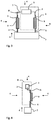
- Fig. 1 shows an arrangement of a sensor for measuring the temperature of a medium 4 in a motor vehicle, wherein the sensor comprises a sensor body 3 and two connecting wires 1, 2.
- the sensor body 3 is electrically insulated from the surrounding medium 4 by means of a sheath 8 which completely surrounds the sensor body 3.
- the sensor body communicates with the medium 4 via the connection wires 1, 2 and the surrounding enclosure 8 thermally conductive in contact.
- the envelope 8 inevitably also largely surrounds the connecting wires 1. 2, at least in the region of the sensor body 3, as a result of which the danger of a short circuit between the connecting wires 1, 2 is considerably reduced.
- the sensor signal can be tapped off at the connecting wires 1, 2 which are kept insulated in this way and fed to the evaluation of an evaluation unit, in particular a control unit.
- the sheath 8 is, as already described above, in particular made of an electrically insulating and thermally conductive material, such as a thermoset or a thermoplastic.
- fillers such as quartz or aluminum powder, a thermal conductivity of up to 10 W / m K (watt / meter Kelvin) can be achieved, compared to 0.2 to 0.5 W / m K of such wraps without fillers , Fig. 2 shows a section through the arrangement.
- connection wire 1, 2 is electrically conductively connected to a contact base 7 via a separate connection contact 5, 6, wherein the sensor body 3, the connection wires 1, 2 and the associated connection contacts 5, 6 are almost completely surrounded by the enclosure 8, and thereby from Medium 4 are both thermally and electrically isolated.
- the connection contacts 5, 6 are designed for example as a stamped grid. At the contact base 7, a sensor signal can be tapped.
- connection contacts 5, 6 in Fig. 2 are each in electrically and thermally conductive contact with a device 9, which is a part of the connection contact 5, 6 for the sake of simplicity.
- Fig. 4 shows a side view of the arrangement.
- the device 9 is not surrounded by the casing, and thus is in direct heat-conducting contact with the medium 4.
- a further reduction of the response time of the measuring process is due to the arrangement in Fig. 3 reached. Characterized in that a large part of the one connecting wire 1 and the associated terminal contact 5 including the associated device 9 are free from the sheath 8, a further increase in the heat-conducting contact surface of the assembly 6 with the medium 4 is achieved with glechzeitiger short-circuit safety.
Landscapes
- Physics & Mathematics (AREA)
- General Physics & Mathematics (AREA)
- Nonlinear Science (AREA)
- Measuring Temperature Or Quantity Of Heat (AREA)
- Thermistors And Varistors (AREA)
Description
- Die Erfindung betrifft eine Anordnung eines Sensors nach dem Oberbegriff des Anspruchs 1.
- Temperatursensoren, insbesondere zur Messung der Medientemperatur wie Öl oder Kühlflüssigkeit in einem Kraftfahrzeug, verändern in der Regel ihre elektrischen Eigenschaften in Abhängigkeit der vorherrschenden Temperatur. Zum Beispiel sinkt bei der Erwärmung eines Sensorbauteils aus Kohle oder einem Halbleitermaterial dessen elektrischer Widerstand. Durch die Widerstandsmessung im Bereich der großen Steigung lässt sich somit die Temperatur ziemlich genau ermitteln. Solche Werkstoffe leiten den Strom heiß besser als kalt, sie werden daher auch Heißleiter oder NTC (Negative Temperature Coefficient)-Widerstände genannt. Metalle wie zum Beispiel Platin zeigen den gegenteiligen Effekt und werden daher PTC (Positive Temperature Coefficient)-Widerstände genannt.
- In der Regel wird der Sensorwiderstand, der vom Medium direkt umgeben ist, mit seinen beiden Anschlüssen, die als Pins oder Beinchen ausgeführt sein können, an eine Versorgungsspannung angelegt. Die an einem zum Sensorwiderstand abfallende Spannung wird in einem Steuergerät ermittelt und ausgewertet.
- Der Temperatureintrag vom Medium zum Sensor kann über die beiden Anschlussbeinchen und gleichzeitig über die Seitenflächen des Sensorbausteins erfolgen. Dabei ist die die Temperatur übertragende Fläche der Anordnung groß, die Ansprechzeit des Messvorgangs daher kurz. Jedoch ist die Gefahr eines Kurzschlusses zwischen den Anschlussbeinchen insbesondere durch Späne, wie sie in einem Motor oder einem Getriebe durch Abrieb zwischen sich drehenden Teilen durchaus vorkommen, groß. Temperatursensoren aus dem Stand der Technik sind beispielsweise aus
DE3044419 A1 ,DE4339631 A1 ,DE4108789 A1 ,DE10052116 A1 ,EP2037247 A2 bekannt. Es ist daher eine Aufgabe der vorliegenden Erfindung, eine Anordnung eines Sensors zur Messung der Temperatur eines Mediums in einem Kraftfahrzeug der eingangs genannten Art derart zu schaffen, dass bei erhöhter Kurzschlusssicherheit gleichzeitig eine möglichst kurze Ansprechzeit garantiert ist.
Diese Aufgabe ist erfindungsgemäß gelöst durch eine Anordnung mit den Merkmalen des Anspruchs 1.
Die erfindungsgemäße Anordnung des Sensors umfasst im wesentlichen einen Sensorkörper und Anschlussdrähte, wobei der Sensorkörper mittels einer den Sensorkörper vollständig umgebenden Umhüllung elektrisch vom Medium isoliert ist, und der Sensor mit dem Medium über die Anschlussdrähte und die umgebende Umhüllung wärmeleitend in Kontakt steht. Dadurch ist der Temperatureintrag vom Medium in den Sensor und damit die Ansprechzeit des Sensors bei der Temperaturmessung gegenüber einem Sensor mit elektrisch und thermisch isolierender Umhüllung deutlich erhöht. Die Umhüllung umgibt zwangsläufig auch größtenteils die Anschlussdrähte, zumindest im Bereich des Sensorkörpers, wodurch die Gefahr eines Kurzschlusses zwischen den Anschlussdrähten, insbesondere durch metallische Späne im Medium, erheblich reduziert wird. Das Sensorsignal kann an den so isoliert gehaltenen Anschlussdrähten abgegriffen und zur Auswertung einer Auswerteeinheit, insbesondere einem Steuergerät zugeführt werden. - Eine weitere Vergrößerung der mit dem Medium wärmeleitend in Kontakt tretende Oberfläche der Anordnung, und somit eine weitere Verkürzung der Ansprechzeit, kann erfindungsgemäß dadurch erreicht werden, indem der thermische Kontakt des Anschlusskontakts mit dem Medium mittels einer zusätzlichen Vorrichtung hergestellt wird. Dabei ist im besonderen die Kontaktoberfläche der Vorrichtung, die nicht von der Umhüllung umgeben ist, und somit mit dem Medium direkt wärmeleitend in Kontakt ist, größer als die Kontaktoberfläche des Anschlusskontakts mit dem Medium. Der Einfachheit halber kann die Vorrichtung jeweils ein Teil des Anschlusskontakts sein, zum Beispiel in einem Stanzgitter integriert sein. Die Umhüllung ist insbesondere aus einem elektrisch isolierenden und thermisch leitenden Material, wie zum Beispiel einem Duroplast oder einem Thermoplast mit Füllstoffen wie Quarz- oder Aluminiumpulver. Durch die Zugabe derartiger Füllstoffe kann eine Wärmeleitfähigkeit von bis zu 10 W/m K (Watt/meter Kelvin), im Vergleich zu 0,2 bis 0,5 W/m K ohne Füllstoffe, erreicht werden.
Vorteilhafterweise ist jeder Anschlussdraht über einen separaten Anschlusskontakt mit einem Kontaktsockel, an dem das Sensorsignal abgegriffen werden kann, elektrisch leitend verbunden. Der Anschlusskontakt kann insbesondere als Stanzgitter ausgeführt sein. - Um die Ansprechzeit des Messverfahrens weiter zu verbessern, kann insbesondere die mit dem Medium wärmeleitend in Kontakt tretende Oberfläche der Anordnung vergrößert werden, indem mindestens ein Teil mindestens eines Anschlusskontakts nicht von der Umhüllung umgeben ist, und somit mit dem Medium direkt wärmeleitend in Berührung kommt.
- Speziell kann die Umhüllung als eine Umspritzung, ein Verguss oder ein mehrteiliges Gehäuse, zum Beispiel aus einem Deckel und einem Gehäuseunterteil, ausgeführt sein.
Je nach Einsatzgebiet kann der Sensor als NTC (Negative Temperature Coefficient)-Widerstand, zum Beispiel aus Kohle oder einem Halbleitermaterial, mit einem negativen Temperaturkoeffizienten, oder als PTC (Positive Temperature Coefficient)-Widerstand, insbesondere aus Metall, mit einem positiven Temperaturkoeffizienten ausgeführt sein.
Eine nähere Beschreibung der vorliegenden Erfindung erfolgt anhand der beigefügten Zeichnungen.
Es zeigen -
Fig. 1 eine Vorderansicht der Anordnung, -
Fig. 2 eine Schnittdarstellung der Anordnung, -
Fig. 3 eine weitere Schnittdarstellung der Anordnung, und -
Fig. 4 eine Seitenansicht der Anordnung. -
Fig. 1 zeigt eine Anordnung eines Sensors zur Messung der Temperatur eines Mediums 4 in einem Kraftfahrzeug, wobei der Sensor einen Sensorkörper 3 und zwei Anschlussdrähte 1, 2 umfasst. Der Sensorkörper 3 ist mittels einer den Sensorkörper 3 vollständig umgebenden Umhüllung 8 elektrisch vom umgebenden Medium 4 isoliert. Der Sensorkörper steht mit dem Medium 4 über die Anschlussdrähte 1, 2 und die umgebende Umhüllung 8 wärmeleitend in Kontakt. Dadurch ist die Ansprechzeit gegenüber einem Sensor mit elektrisch und thermisch isolierender Umhüllung 8 deutlich erhöht. Die Umhüllung 8 umgibt zwangsläufig auch größtenteils die Anschlussdrähte 1. 2, zumindest im Bereich des Sensorkörpers 3, wodurch die Gefahr eines Kurzschlusses zwischen den Anschlussdrähten 1, 2 erheblich reduziert ist. Das Sensorsignal kann an den so isoliert gehaltenen Anschlussdrähten 1, 2 abgegriffen und zur Auswertung einer Auswerteeinheit, insbesondere einem Steuergerät zugeführt werden.
Die Umhüllung 8 ist, wie weiter oben schon beschrieben, insbesondere aus einem elektrisch isolierenden und thermisch leitenden Material, wie zum Beispiel einem Duroplast oder einem Thermoplast. Durch die Zugabe von Füllstoffen wie Quarz- oder Aluminiumpulver kann eine Wärmeleitfähigkeit von bis zu 10 W/m K (Watt/meter Kelvin), im Vergleich zu 0,2 bis 0,5 W/m K von derartigen Umhüllungen ohne Füllstoffe, erreicht werden.
Fig. 2 zeigt einen Schnitt durch die Anordnung. Jeder Anschlussdraht 1, 2 ist über einen separaten Anschlusskontakt 5, 6 mit einem Kontaktsockel 7 elektrisch leitend verbunden, wobei der Sensorkörper 3, die Anschlussdrähte 1, 2 und die zugehörigen Anschlusskontakte 5, 6 nahezu vollständig von der Umhüllung 8 umgeben sind, und dadurch vom Medium 4 sowohl thermisch als auch elektrisch isoliert sind. Die Anschlusskontakte 5, 6 sind beispielsweise als Stanzgitter ausgeführt. Am Kontaktsockel 7 ist ein Sensorsignal abgreifbar. - Durch diese Anordnung ist die Gefahr eines Kurzschlusses zwischen den Anschlussdrähten 1, 2 bzw. zwischen den Anschlusskontakten 5, 6 insbesondere durch Späne, wie sie in einem Motor oder einem Getriebe durch Abrieb zwischen sich drehenden Teilen nicht selten vorkommen, gering gehalten.
- Die Anschlusskontakte 5, 6 in
Fig. 2 stehen jeweils in elektrisch und wärmeleitendem Kontakt mit einer Vorrichtung 9, die der Einfachheit halber ein Teil des Anschlusskontakts 5, 6 ist. -
Fig. 4 zeigt eine Seitenansicht der Anordnung. Dabei ist zumindest ein Teil der Vorrichtung 9 nicht von der Umhüllung umgeben, und ist somit mit dem Medium 4 direkt wärmeleitend in Kontakt. Dadurch, dass die Kontaktoberfläche der Vorrichtung 9, die frei von der Umhüllung 8 ist, und somit mit dem Medium 4 direkt wärmeleitend in Kontakt steht, größer ist als die Kontaktoberfläche des Anschlusskontakts 5, 6 mit dem Medium 4, ist die die Temperatur übertragende Fläche der Anordnung relativ groß. Das führt zu einer relativ kurzen Ansprechzeit des Messvorgangs. Dadurch können auch schnelle Temperaturschwankungen des Mediums 4 erfasst werden. - Eine weitere Verkürzung der Ansprechzeit des Messvorgangs wird durch die Anordnung in
Fig. 3 erreicht. Dadurch, dass ein großer Teil des einen Anschlussdrahtes 1 und der zugehörige Anschlusskontakt 5 einschließlich der dazugehörigen Vorrichtung 9 frei von der Umhüllung 8 sind, wird bei glechzeitiger Kurzschlusssicherheit eine weitere Erhöhung der wärmeleitenden Kontaktoberfläche der Anordnung 6 mit dem Medium 4 erzielt.
Claims (6)
- Anordnung eines Sensors, umfassend einen Sensorkörper (3) und zwei Anschlussdrähte (1, 2), zur Messung der Temperatur eines Mediums (4) in einem Kraftfahrzeug, wobei
der Sensorkörper (3) mittels einer den Sensorkörper (3) vollständig umgebenden Umhüllung (8) elektrisch vom Medium (4) isoliert ist, wobei der Sensorkörper (3) mit dem Medium (4) über die Anschlussdrähte (1, 2) und die umgebende Umhüllung (8) wärmeleitend in Kontakt steht, dadurch gekennzeichnet, dass:
jeder Anschlussdraht (1, 2) über einen separaten Anschlusskontakt (5, 6) mit einem Kontaktsockel (7) elektrisch leitend verbunden ist, wobei am Kontaktsockel (7) ein Sensorsignal abgreifbar ist, mindestens ein Teil mindestens eines Anschlusskontakts (5, 6) nicht von der Umhüllung (8) umgeben ist, und somit mit dem Medium (4) direkt wärmeleitend in Kontakt ist, und der thermische Kontakt des Anschlusskontakts (5, 6) mit dem Medium mittels einer Vorrichtung (9) hergestellt ist, wobei die Kontaktoberfläche der Vorrichtung (9), die nicht von der Umhüllung (8) umgeben ist, und somit mit dem Medium (4) direkt wärmeleitend in Kontakt ist, größer ist als die Kontaktoberfläche des Anschlusskontakts (5, 6). - Anordnung eines Sensors nach Anspruch 1, dadurch gekennzeichnet, dass
die Vorrichtung (9) jeweils ein Teil des Anschlusskontakts (5, 6) ist. - Anordnung eines Sensors nach Anspruch 1 oder 2 , dadurch gekennzeichnet, dass die elektrisch isolierende Umhüllung (8) aus einem Material wie einem Duroplast oder einem Thermoplast mit Füllstoffen wie Quarz- oder Aluminiumpulver zur Erhöhung der Wärmeleitfähigkeit ist.
- Anordnung eines Sensors nach Anspruch 1 ,2 oder 3, dadurch gekennzeichnet, dass
die Anschlusskontakte (5, 6) als Stanzgitter ausgeführt sind. - Anordnung eines Sensors nach einem der vorhergehenden Ansprüche, dadurch gekennzeichnet, dass
die Umhüllung (8) eine Umspritzung, ein Verguss oder ein mehrteiliges Gehäuse ist. - Anordnung eines Sensors nach einem der vorhergehenden Ansprüche, dadurch gekennzeichnet, dass
der Sensor ein Widerstand mit einem positiven oder negativen Temperaturkoeffizienten ist.
Applications Claiming Priority (2)
| Application Number | Priority Date | Filing Date | Title |
|---|---|---|---|
| DE102013219092.1A DE102013219092B4 (de) | 2013-09-23 | 2013-09-23 | Anordnung eines Temperatursensors mit einer elektrisch isolierenden Umhüllung |
| PCT/EP2014/069510 WO2015039966A1 (de) | 2013-09-23 | 2014-09-12 | Anordnung eines temperatursensors mit einer elektrisch isolierenden umhüllung |
Publications (2)
| Publication Number | Publication Date |
|---|---|
| EP2992306A1 EP2992306A1 (de) | 2016-03-09 |
| EP2992306B1 true EP2992306B1 (de) | 2018-07-11 |
Family
ID=51542364
Family Applications (1)
| Application Number | Title | Priority Date | Filing Date |
|---|---|---|---|
| EP14766457.7A Active EP2992306B1 (de) | 2013-09-23 | 2014-09-12 | Anordnung eines temperatursensors mit einer elektrisch isolierenden umhüllung |
Country Status (5)
| Country | Link |
|---|---|
| US (1) | US10088369B2 (de) |
| EP (1) | EP2992306B1 (de) |
| JP (1) | JP6239121B2 (de) |
| DE (1) | DE102013219092B4 (de) |
| WO (1) | WO2015039966A1 (de) |
Families Citing this family (2)
| Publication number | Priority date | Publication date | Assignee | Title |
|---|---|---|---|---|
| EP3506533B1 (de) * | 2017-12-29 | 2022-03-30 | Nokia Technologies Oy | Erfassungsvorrichtung und -system |
| DE102018102709A1 (de) * | 2018-02-07 | 2019-08-08 | Tdk Electronics Ag | Temperatursensor und ein Verfahren zur Herstellung des Temperatursensors |
Citations (2)
| Publication number | Priority date | Publication date | Assignee | Title |
|---|---|---|---|---|
| DE10052116A1 (de) * | 2000-10-19 | 2002-05-08 | Kriwan Ind Elektronik Gmbh | Verbesserung der Ansprechgeschwindigkeit von Temperatursensoren |
| EP2037247A2 (de) * | 2007-09-14 | 2009-03-18 | EPIQ Sensor-Nite N.V. | Temperatursensor |
Family Cites Families (16)
| Publication number | Priority date | Publication date | Assignee | Title |
|---|---|---|---|---|
| JPS5226250A (en) * | 1975-08-25 | 1977-02-26 | Automob Antipollut & Saf Res Center | Detector for liquid level and temperature |
| IT1100526B (it) * | 1977-12-05 | 1985-09-28 | Bendix Corp | Percettore della temperatura di un fluido |
| US4142170A (en) | 1977-12-05 | 1979-02-27 | The Bendix Corporation | High response temperature sensor |
| US4246787A (en) * | 1979-06-13 | 1981-01-27 | Texas Instruments Incorporated | Fast response temperature sensor and method of making |
| DE3044419A1 (de) | 1980-11-26 | 1982-06-24 | Robert Bosch Gmbh, 7000 Stuttgart | Temperaturfuehler |
| DE3134166A1 (de) * | 1981-08-28 | 1983-03-10 | Robert Bosch Gmbh, 7000 Stuttgart | Temperaturfuehler |
| DE4108789C5 (de) * | 1991-01-17 | 2005-06-16 | Mannesmann Vdo Ag | Temperatursensor |
| DE9218936U1 (de) * | 1992-11-03 | 1996-07-18 | Henschel Kunststofftechnik Gmbh, 29693 Hodenhagen | Temperaturmeßeinrichtung mit umspritztem Heißleiter |
| DE4339631C2 (de) * | 1993-06-03 | 1999-11-04 | Mannesmann Vdo Ag | Temperatursensor |
| DE19938868B4 (de) * | 1999-08-17 | 2005-11-24 | Siemens Ag | Sensoreinrichtung und Verfahren zum Herstellen einer Sensoreinrichtung |
| DE10156753A1 (de) * | 2001-11-19 | 2003-06-05 | Epcos Ag | Meßfühler und Meßfühleranordnung |
| US7046116B2 (en) | 2002-11-12 | 2006-05-16 | Heraeus Sensor Technology Gmbh | Temperature probe and its use |
| DE10322166B4 (de) * | 2002-11-12 | 2005-04-28 | Heraeus Sensor Technology Gmbh | Temperaturfühler und seine Verwendung |
| US20040101031A1 (en) * | 2002-11-25 | 2004-05-27 | Ford Global Technologies, Inc. | Temperature sensor with improved response time |
| DE102006007221B3 (de) * | 2006-02-15 | 2007-09-06 | Epcos Ag | Fühler und Temperaturmessvorrichtung |
| DE102010002806A1 (de) * | 2010-03-12 | 2011-09-15 | Robert Bosch Gmbh | Sensor |
-
2013
- 2013-09-23 DE DE102013219092.1A patent/DE102013219092B4/de active Active
-
2014
- 2014-09-12 US US15/023,733 patent/US10088369B2/en active Active
- 2014-09-12 JP JP2016537347A patent/JP6239121B2/ja active Active
- 2014-09-12 WO PCT/EP2014/069510 patent/WO2015039966A1/de not_active Ceased
- 2014-09-12 EP EP14766457.7A patent/EP2992306B1/de active Active
Patent Citations (2)
| Publication number | Priority date | Publication date | Assignee | Title |
|---|---|---|---|---|
| DE10052116A1 (de) * | 2000-10-19 | 2002-05-08 | Kriwan Ind Elektronik Gmbh | Verbesserung der Ansprechgeschwindigkeit von Temperatursensoren |
| EP2037247A2 (de) * | 2007-09-14 | 2009-03-18 | EPIQ Sensor-Nite N.V. | Temperatursensor |
Also Published As
| Publication number | Publication date |
|---|---|
| US20160231183A1 (en) | 2016-08-11 |
| DE102013219092A1 (de) | 2015-03-26 |
| JP2016529511A (ja) | 2016-09-23 |
| EP2992306A1 (de) | 2016-03-09 |
| DE102013219092B4 (de) | 2015-04-09 |
| WO2015039966A1 (de) | 2015-03-26 |
| US10088369B2 (en) | 2018-10-02 |
| JP6239121B2 (ja) | 2017-11-29 |
Similar Documents
| Publication | Publication Date | Title |
|---|---|---|
| DE102007034757B4 (de) | Stromsensor | |
| DE102012211924B4 (de) | Halbleitermodul mit einem in einer Anschlusslasche integrierten Shunt-Widerstand und Verfahren zur Ermittlung eines durch einen Lastanschluss eines Halbleitermoduls fließenden Stromes | |
| DE102016107401A1 (de) | Steckvorrichtung mit Temperaturerfassung | |
| DE102013210128A1 (de) | Einstückig ausgebildete Stromsensorvorrichtung | |
| DE102019211733A1 (de) | Temperatursensor eines thermoüberwachungssystems zur verwendung in stromverteilungssystemen | |
| DE202018002686U1 (de) | Steckverbinder zum Trennen und Verbinden von zumindest einem elektrischen Kontakt zum Laden einer Akkueinheit eines Kraftfahrzeugs | |
| WO2015131883A1 (de) | Steckverbinder mit sensoranordnung | |
| EP3463969B1 (de) | Stecker, insbesondere mit einem fahrzeugladekabel eines elektro- oder hybridfahrzeuges | |
| DE102009017518A1 (de) | Schaltungsschutzvorrichtung einschließlich Widerstand und Sicherungselement | |
| DE102011111081A1 (de) | Batteriesensor | |
| DE102015216789A1 (de) | Anschlussvorrichtung zum Anschließen eines Messgerätes an einen Anschlusspol eines Energiespeichers eines Kraftfahrzeugs | |
| DE102015104170B4 (de) | Anschlusssteckvorrichtung | |
| EP2992306B1 (de) | Anordnung eines temperatursensors mit einer elektrisch isolierenden umhüllung | |
| DE102015218290A1 (de) | Vorrichtung für Hoch-/Mittel-/Niederspannungsstrommessung | |
| DE202015106844U1 (de) | Stecker mit einem Fahrzeugladekabel eines Elektro- oder Hybridfahrzeuges | |
| EP2992307B1 (de) | Anordnung eines temperatursensors mit einer elektrisch und thermisch isolierenden umhüllung | |
| DE102012204817A1 (de) | Temperatursensor | |
| EP3671241A1 (de) | Widerstandsbaugruppe für einen batteriesensor und batteriesensor | |
| DE102013220516A1 (de) | Messeinrichtung | |
| EP2997339B1 (de) | Anordnung eines sensors zur messung der temperatur eines mediums in einem kraftfahrzeug | |
| DE202011109734U1 (de) | Widerstand, insbesondere Strommesswiderstand | |
| DE102011120276A1 (de) | Widerstand, insbesondere Strommesswiderstand | |
| DE202011108919U1 (de) | Beleuchtungseinrichtung | |
| DE102022204223A1 (de) | Vorrichtung zur Temperaturmessung einer thermischen Quelle und Temperatursensor | |
| EP4147543A1 (de) | Gehäuse und elektrisches gerät |
Legal Events
| Date | Code | Title | Description |
|---|---|---|---|
| PUAI | Public reference made under article 153(3) epc to a published international application that has entered the european phase |
Free format text: ORIGINAL CODE: 0009012 |
|
| 17P | Request for examination filed |
Effective date: 20151204 |
|
| AK | Designated contracting states |
Kind code of ref document: A1 Designated state(s): AL AT BE BG CH CY CZ DE DK EE ES FI FR GB GR HR HU IE IS IT LI LT LU LV MC MK MT NL NO PL PT RO RS SE SI SK SM TR |
|
| AX | Request for extension of the european patent |
Extension state: BA ME |
|
| DAX | Request for extension of the european patent (deleted) | ||
| GRAP | Despatch of communication of intention to grant a patent |
Free format text: ORIGINAL CODE: EPIDOSNIGR1 |
|
| INTG | Intention to grant announced |
Effective date: 20180201 |
|
| GRAS | Grant fee paid |
Free format text: ORIGINAL CODE: EPIDOSNIGR3 |
|
| GRAA | (expected) grant |
Free format text: ORIGINAL CODE: 0009210 |
|
| AK | Designated contracting states |
Kind code of ref document: B1 Designated state(s): AL AT BE BG CH CY CZ DE DK EE ES FI FR GB GR HR HU IE IS IT LI LT LU LV MC MK MT NL NO PL PT RO RS SE SI SK SM TR |
|
| REG | Reference to a national code |
Ref country code: GB Ref legal event code: FG4D Free format text: NOT ENGLISH |
|
| REG | Reference to a national code |
Ref country code: CH Ref legal event code: EP |
|
| REG | Reference to a national code |
Ref country code: AT Ref legal event code: REF Ref document number: 1017364 Country of ref document: AT Kind code of ref document: T Effective date: 20180715 |
|
| REG | Reference to a national code |
Ref country code: IE Ref legal event code: FG4D Free format text: LANGUAGE OF EP DOCUMENT: GERMAN |
|
| REG | Reference to a national code |
Ref country code: DE Ref legal event code: R096 Ref document number: 502014008828 Country of ref document: DE |
|
| REG | Reference to a national code |
Ref country code: FR Ref legal event code: PLFP Year of fee payment: 5 |
|
| REG | Reference to a national code |
Ref country code: NL Ref legal event code: MP Effective date: 20180711 |
|
| REG | Reference to a national code |
Ref country code: LT Ref legal event code: MG4D |
|
| PG25 | Lapsed in a contracting state [announced via postgrant information from national office to epo] |
Ref country code: NL Free format text: LAPSE BECAUSE OF FAILURE TO SUBMIT A TRANSLATION OF THE DESCRIPTION OR TO PAY THE FEE WITHIN THE PRESCRIBED TIME-LIMIT Effective date: 20180711 |
|
| PG25 | Lapsed in a contracting state [announced via postgrant information from national office to epo] |
Ref country code: PL Free format text: LAPSE BECAUSE OF FAILURE TO SUBMIT A TRANSLATION OF THE DESCRIPTION OR TO PAY THE FEE WITHIN THE PRESCRIBED TIME-LIMIT Effective date: 20180711 Ref country code: RS Free format text: LAPSE BECAUSE OF FAILURE TO SUBMIT A TRANSLATION OF THE DESCRIPTION OR TO PAY THE FEE WITHIN THE PRESCRIBED TIME-LIMIT Effective date: 20180711 Ref country code: IS Free format text: LAPSE BECAUSE OF FAILURE TO SUBMIT A TRANSLATION OF THE DESCRIPTION OR TO PAY THE FEE WITHIN THE PRESCRIBED TIME-LIMIT Effective date: 20181111 Ref country code: SE Free format text: LAPSE BECAUSE OF FAILURE TO SUBMIT A TRANSLATION OF THE DESCRIPTION OR TO PAY THE FEE WITHIN THE PRESCRIBED TIME-LIMIT Effective date: 20180711 Ref country code: FI Free format text: LAPSE BECAUSE OF FAILURE TO SUBMIT A TRANSLATION OF THE DESCRIPTION OR TO PAY THE FEE WITHIN THE PRESCRIBED TIME-LIMIT Effective date: 20180711 Ref country code: GR Free format text: LAPSE BECAUSE OF FAILURE TO SUBMIT A TRANSLATION OF THE DESCRIPTION OR TO PAY THE FEE WITHIN THE PRESCRIBED TIME-LIMIT Effective date: 20181012 Ref country code: NO Free format text: LAPSE BECAUSE OF FAILURE TO SUBMIT A TRANSLATION OF THE DESCRIPTION OR TO PAY THE FEE WITHIN THE PRESCRIBED TIME-LIMIT Effective date: 20181011 Ref country code: BG Free format text: LAPSE BECAUSE OF FAILURE TO SUBMIT A TRANSLATION OF THE DESCRIPTION OR TO PAY THE FEE WITHIN THE PRESCRIBED TIME-LIMIT Effective date: 20181011 Ref country code: LT Free format text: LAPSE BECAUSE OF FAILURE TO SUBMIT A TRANSLATION OF THE DESCRIPTION OR TO PAY THE FEE WITHIN THE PRESCRIBED TIME-LIMIT Effective date: 20180711 |
|
| PGFP | Annual fee paid to national office [announced via postgrant information from national office to epo] |
Ref country code: DE Payment date: 20180930 Year of fee payment: 5 |
|
| PG25 | Lapsed in a contracting state [announced via postgrant information from national office to epo] |
Ref country code: HR Free format text: LAPSE BECAUSE OF FAILURE TO SUBMIT A TRANSLATION OF THE DESCRIPTION OR TO PAY THE FEE WITHIN THE PRESCRIBED TIME-LIMIT Effective date: 20180711 Ref country code: LV Free format text: LAPSE BECAUSE OF FAILURE TO SUBMIT A TRANSLATION OF THE DESCRIPTION OR TO PAY THE FEE WITHIN THE PRESCRIBED TIME-LIMIT Effective date: 20180711 Ref country code: AL Free format text: LAPSE BECAUSE OF FAILURE TO SUBMIT A TRANSLATION OF THE DESCRIPTION OR TO PAY THE FEE WITHIN THE PRESCRIBED TIME-LIMIT Effective date: 20180711 Ref country code: ES Free format text: LAPSE BECAUSE OF FAILURE TO SUBMIT A TRANSLATION OF THE DESCRIPTION OR TO PAY THE FEE WITHIN THE PRESCRIBED TIME-LIMIT Effective date: 20180711 |
|
| REG | Reference to a national code |
Ref country code: DE Ref legal event code: R097 Ref document number: 502014008828 Country of ref document: DE |
|
| PG25 | Lapsed in a contracting state [announced via postgrant information from national office to epo] |
Ref country code: MC Free format text: LAPSE BECAUSE OF FAILURE TO SUBMIT A TRANSLATION OF THE DESCRIPTION OR TO PAY THE FEE WITHIN THE PRESCRIBED TIME-LIMIT Effective date: 20180711 Ref country code: RO Free format text: LAPSE BECAUSE OF FAILURE TO SUBMIT A TRANSLATION OF THE DESCRIPTION OR TO PAY THE FEE WITHIN THE PRESCRIBED TIME-LIMIT Effective date: 20180711 Ref country code: CZ Free format text: LAPSE BECAUSE OF FAILURE TO SUBMIT A TRANSLATION OF THE DESCRIPTION OR TO PAY THE FEE WITHIN THE PRESCRIBED TIME-LIMIT Effective date: 20180711 Ref country code: EE Free format text: LAPSE BECAUSE OF FAILURE TO SUBMIT A TRANSLATION OF THE DESCRIPTION OR TO PAY THE FEE WITHIN THE PRESCRIBED TIME-LIMIT Effective date: 20180711 Ref country code: IT Free format text: LAPSE BECAUSE OF FAILURE TO SUBMIT A TRANSLATION OF THE DESCRIPTION OR TO PAY THE FEE WITHIN THE PRESCRIBED TIME-LIMIT Effective date: 20180711 |
|
| REG | Reference to a national code |
Ref country code: CH Ref legal event code: PL |
|
| PLBE | No opposition filed within time limit |
Free format text: ORIGINAL CODE: 0009261 |
|
| STAA | Information on the status of an ep patent application or granted ep patent |
Free format text: STATUS: NO OPPOSITION FILED WITHIN TIME LIMIT |
|
| PG25 | Lapsed in a contracting state [announced via postgrant information from national office to epo] |
Ref country code: SM Free format text: LAPSE BECAUSE OF FAILURE TO SUBMIT A TRANSLATION OF THE DESCRIPTION OR TO PAY THE FEE WITHIN THE PRESCRIBED TIME-LIMIT Effective date: 20180711 Ref country code: DK Free format text: LAPSE BECAUSE OF FAILURE TO SUBMIT A TRANSLATION OF THE DESCRIPTION OR TO PAY THE FEE WITHIN THE PRESCRIBED TIME-LIMIT Effective date: 20180711 Ref country code: SK Free format text: LAPSE BECAUSE OF FAILURE TO SUBMIT A TRANSLATION OF THE DESCRIPTION OR TO PAY THE FEE WITHIN THE PRESCRIBED TIME-LIMIT Effective date: 20180711 |
|
| REG | Reference to a national code |
Ref country code: BE Ref legal event code: MM Effective date: 20180930 |
|
| 26N | No opposition filed |
Effective date: 20190412 |
|
| GBPC | Gb: european patent ceased through non-payment of renewal fee |
Effective date: 20181011 |
|
| REG | Reference to a national code |
Ref country code: IE Ref legal event code: MM4A |
|
| PG25 | Lapsed in a contracting state [announced via postgrant information from national office to epo] |
Ref country code: LU Free format text: LAPSE BECAUSE OF NON-PAYMENT OF DUE FEES Effective date: 20180912 |
|
| REG | Reference to a national code |
Ref country code: DE Ref legal event code: R231 Ref document number: 502014008828 Country of ref document: DE |
|
| PG25 | Lapsed in a contracting state [announced via postgrant information from national office to epo] |
Ref country code: IE Free format text: LAPSE BECAUSE OF NON-PAYMENT OF DUE FEES Effective date: 20180912 Ref country code: DE Free format text: LAPSE BECAUSE OF THE APPLICANT RENOUNCES Effective date: 20190628 |
|
| PG25 | Lapsed in a contracting state [announced via postgrant information from national office to epo] |
Ref country code: SI Free format text: LAPSE BECAUSE OF FAILURE TO SUBMIT A TRANSLATION OF THE DESCRIPTION OR TO PAY THE FEE WITHIN THE PRESCRIBED TIME-LIMIT Effective date: 20180711 Ref country code: LI Free format text: LAPSE BECAUSE OF NON-PAYMENT OF DUE FEES Effective date: 20180930 Ref country code: CH Free format text: LAPSE BECAUSE OF NON-PAYMENT OF DUE FEES Effective date: 20180930 Ref country code: BE Free format text: LAPSE BECAUSE OF NON-PAYMENT OF DUE FEES Effective date: 20180930 |
|
| PG25 | Lapsed in a contracting state [announced via postgrant information from national office to epo] |
Ref country code: GB Free format text: LAPSE BECAUSE OF NON-PAYMENT OF DUE FEES Effective date: 20181011 |
|
| PG25 | Lapsed in a contracting state [announced via postgrant information from national office to epo] |
Ref country code: MT Free format text: LAPSE BECAUSE OF FAILURE TO SUBMIT A TRANSLATION OF THE DESCRIPTION OR TO PAY THE FEE WITHIN THE PRESCRIBED TIME-LIMIT Effective date: 20180711 |
|
| PG25 | Lapsed in a contracting state [announced via postgrant information from national office to epo] |
Ref country code: TR Free format text: LAPSE BECAUSE OF FAILURE TO SUBMIT A TRANSLATION OF THE DESCRIPTION OR TO PAY THE FEE WITHIN THE PRESCRIBED TIME-LIMIT Effective date: 20180711 |
|
| PG25 | Lapsed in a contracting state [announced via postgrant information from national office to epo] |
Ref country code: PT Free format text: LAPSE BECAUSE OF FAILURE TO SUBMIT A TRANSLATION OF THE DESCRIPTION OR TO PAY THE FEE WITHIN THE PRESCRIBED TIME-LIMIT Effective date: 20180711 |
|
| PG25 | Lapsed in a contracting state [announced via postgrant information from national office to epo] |
Ref country code: CY Free format text: LAPSE BECAUSE OF FAILURE TO SUBMIT A TRANSLATION OF THE DESCRIPTION OR TO PAY THE FEE WITHIN THE PRESCRIBED TIME-LIMIT Effective date: 20180711 Ref country code: HU Free format text: LAPSE BECAUSE OF FAILURE TO SUBMIT A TRANSLATION OF THE DESCRIPTION OR TO PAY THE FEE WITHIN THE PRESCRIBED TIME-LIMIT; INVALID AB INITIO Effective date: 20140912 Ref country code: MK Free format text: LAPSE BECAUSE OF NON-PAYMENT OF DUE FEES Effective date: 20180711 |
|
| REG | Reference to a national code |
Ref country code: AT Ref legal event code: MM01 Ref document number: 1017364 Country of ref document: AT Kind code of ref document: T Effective date: 20190912 |
|
| PG25 | Lapsed in a contracting state [announced via postgrant information from national office to epo] |
Ref country code: AT Free format text: LAPSE BECAUSE OF NON-PAYMENT OF DUE FEES Effective date: 20190912 |
|
| P01 | Opt-out of the competence of the unified patent court (upc) registered |
Effective date: 20230530 |
|
| PGFP | Annual fee paid to national office [announced via postgrant information from national office to epo] |
Ref country code: FR Payment date: 20250922 Year of fee payment: 12 |